Fitzgrevye MUWZ User manual

Fitzgrevye
MUWZ
Euro format (12hp)
Version 1.1

Table of Contents
Introduction ............................................................................................................................................3
Build Options...........................................................................................................................................4
Power Consumption ...............................................................................................................................4
PCB..........................................................................................................................................................5
PCB Addenda...........................................................................................................................................6
Schematic –Main PCB ............................................................................................................................7
Schematic –Control PCB.........................................................................................................................8
BOM - Main PCB......................................................................................................................................9
BOM - Control PCB................................................................................................................................11
Notes on components...........................................................................................................................12
Assembly...............................................................................................................................................14
Transpose Modification ....................................................................................................................25
Adjustments..........................................................................................................................................27
Display Brightness.............................................................................................................................27
CV Output..........................................................................................................................................27
Appendix 1 –Rohm LB-303xK Display Pin-out......................................................................................28
Appendix 2 - MIDI Output.....................................................................................................................29
© Mark Graves 2020

Introduction
MUWZ is a Eurorack emulation of the Triadex MUSE, a 1972 “computer musical synthesizer” that
was invented by Marvin Minsky and Edward Fredkin of the Massachusetts Institute of Technology.
While the original MUSE documentation referred to it as a “computer”, it is actually a collection of
counters, shift registers and simple logic circuits.
MUWZ creates original melodies from algorithmic processes. There are no pre-programmed
sequences or random sources involved.
The original MUSE was not a "synthesizer" in the current sense of the word, as it only played a fixed
level square wave. MUWZ omits the sound generation and acts as a monophonic sequencer with
standard 1V/octave CV and GATE outputs, and inputs for external CLOCK and RESET.
With MUWZ, what sound you generate is up to you and your modular setup!
MUWZ has the following capabilities:
32 Selectable SCALES
CV control of SCALE or TRANSPOSE
3 clocking modes
3 Gate modes
Optional MIDI output
Additional counter outputs (C16, C12)
Inputs:
oClock: >1.5V = “on”
oReset: >1.5V = “on”
oCV: ± 5V usable range
Outputs:
oGATE: 0-5V
oCV 0-5V
For more information on the original MUSE, just Google “Triadex Muse”.
Don Tillman has created an excellent Javascript emulation of the original MUSE at
http://till.com/articles/muse/
There is a lot hiding in the MUSE (and MUWZ!). It's more complex and deep than you would think at
first sight.

Build Options
As standard, the module is designed to be built using Alpha Taiwan 14mm potentiometers with
transparent shafts and transparent knobs, with 3mm bi-colour LEDs underneath.
The module can also be built using “standard” Alpha 14mm potentiometers; the bicolour LEDs will
then not be visible and can be omitted (this is possible but not recommended).
The SCALE and CV AMT controls can be either vertical 9mm presets or 9mm potentiometers, though
panel space is limited for knobs on these controls.
The jack sockets are not PCB mounted, so that the builder can select their favourite brand and type.
Use of banana plugs is also supported as there are no switched contacts required on any of the
sockets. The panel holes for the jack sockets are 6mm diameter.
PR1 sets the display brightness. It is strongly recommended that this is left at its “maximum” setting
(fully clockwise viewed from the top of the PCB) as the display brightness can be set from the front
panel controls. The stated power consumption figures are for the “maximum”/fully-clockwise
setting of PR1.
Power Consumption
+12V: 15mA with all controls illuminated, minimum brightness configuration setting.
55mA with all controls illuminated, maximum brightness configuration setting.
-12V 6mA
Depth behind front panel: 35mm
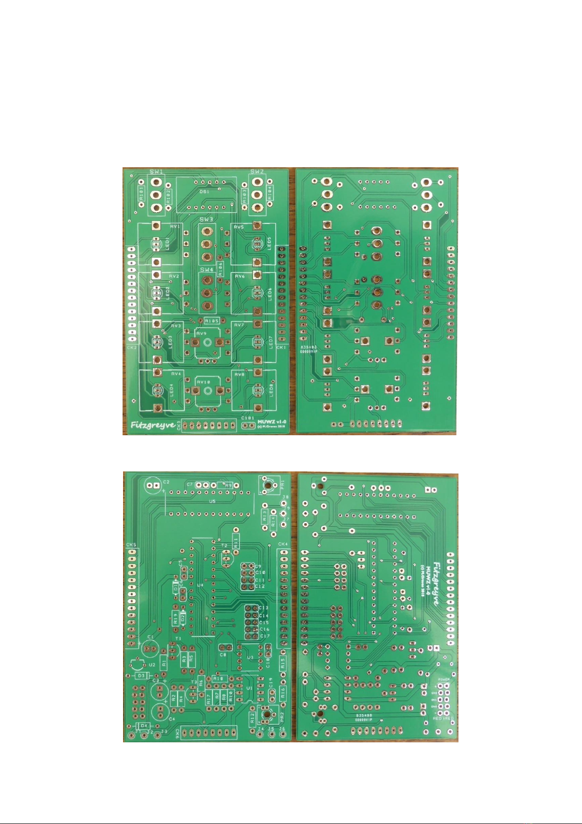
PCB
There are two PCBs, one holding the Controls, and the Main PCB comprising the processor, display
driver, and control voltage processing.
Control PCB:
Main PCB:

PCB Addenda
V1-0 PCB only.
The screen print for regulator U2 is reversed.
One link wire is required on the Control PCB.
Fitting of a second voltage regulator to the Main PCB is recommended (See “Assembly/
Main PCB V1-0 Modification”).
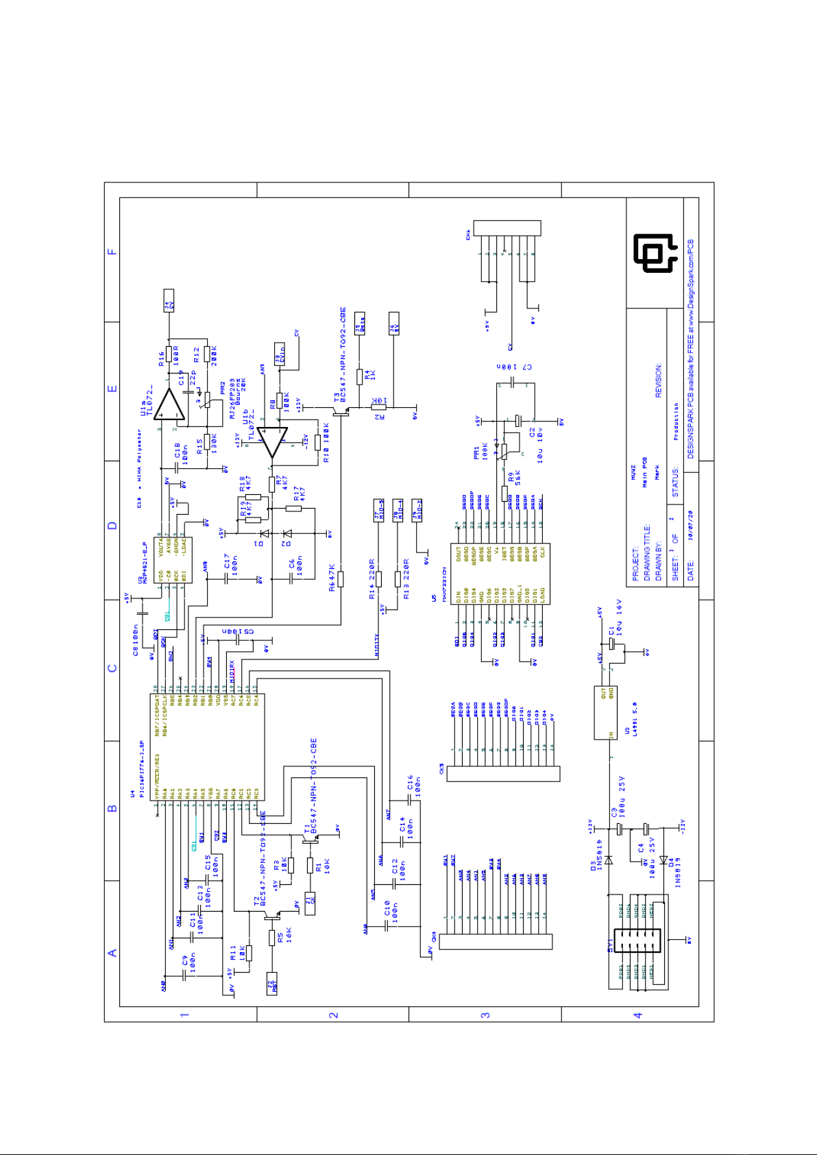
Schematic –Main PCB
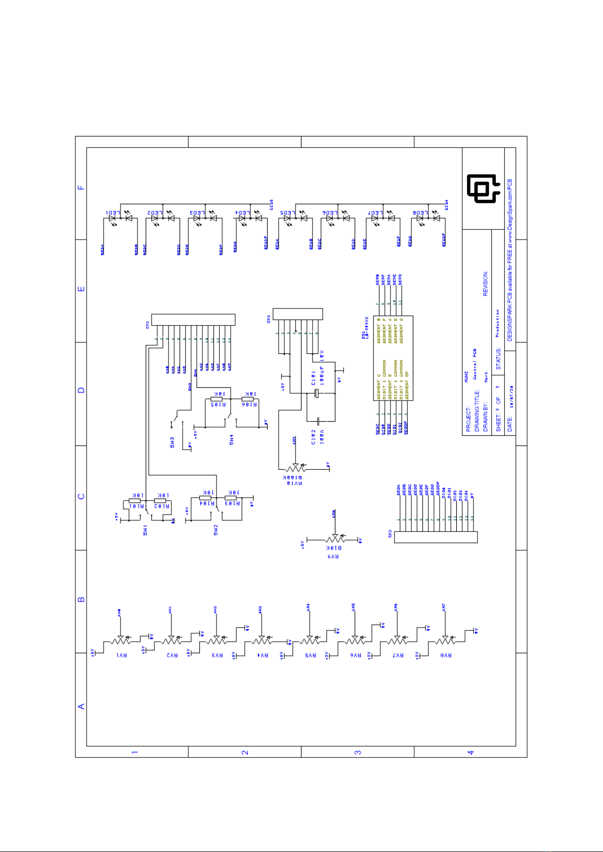
Schematic –Control PCB

BOM - Main PCB
Ref Name
Component
Value
Notes
C1
Electrolytic Capacitor
2.5mm
10u 10V
C10
capacitor 2.5mm
100n
C11
capacitor 2.5mm
100n
C12
capacitor 2.5mm
100n
C13
capacitor 2.5mm
100n
C14
capacitor 2.5mm
100n
C15
capacitor 2.5mm
100n
C16
capacitor 2.5mm
100n
C17
capacitor 2.5mm
100n
C18
capacitor 2.5mm
100n polyester
e.g. Wima MKS0C031000C00MS
C19
capacitor 2.5mm
22p
C2
Electrolytic Capacitor
radial 2.5mm
10u 10v
C3
Electrolytic Capacitor
radial 2.5mm
100u or 47u 25V
C4
Electrolytic Capacitor
radial 2.5mm
100u or 47u 25V
C5
capacitor 2.5mm
100n
Ceramic
C6
capacitor 2.5mm
100n
Ceramic
C7
capacitor 2.5mm
100n
Ceramic
C8
capacitor 2.5mm
100n
Ceramic
C9
capacitor 2.5mm
100n
Ceramic
CK4
14 pin SIL Connector
female
CK5
14 pin SIL Connector
female
CK6
8 pin SIL Connector
female
D1
1N914
Or 1N4148
D2
1N914
Or 1N4148
D3
1N5819
D4
1N5819
PR1
6mm cermet trimmer
100K
PR2
6mm or 10-turn cermet
trimmer
20K
Ideally Bourns RJ26FP203
R1
RESISTOR
10K
R10
RESISTOR
200K
R11
RESISTOR
10K

Ref Name
Component
Value
Notes
R12
RESISTOR
200K
R13
RESISTOR
220R 500mW
R14
RESISTOR
220R 500mW
R15
RESISTOR
130K
R16
RESISTOR
100R
R17
RESISTOR
4K7
* matched –see note below
R18
RESISTOR
4K7
* matched–see note below
R19
RESISTOR
4K7
* matched–see note below
R2
RESISTOR
10K
R3
RESISTOR
10K
R4
RESISTOR
1K
R5
RESISTOR
10K
R6
RESISTOR
47K
R7
RESISTOR
4K7
* matched–see note below
R8
RESISTOR
100K
R9
RESISTOR
56K
T1
BC547 TO92 CBE
T2
BC547 TO92 CBE
T3
BC547 TO92 CBE
U1
TL072
U2
L4931 5.0V 250mA
regulator T092
Or 78L05 if U6 also fitted
U3
MCP4821-E_P
U4
PIC16F1776-I_SP
U5
MAX7221CN
U6
78L05 5V 100ma regulator
Not on Schematic - See text
SV1
EURO POWER HEADER 10 x 2 pin
1 off
DIL socket 28 pin skinny PDIP/0.3”
1 off
DIL socket 24 pin skinny PDIP/0.3”
2 off
DIL socket 8 pin
30cm
Hookup wire
5 off
Mono 3.5mm jack socket
R7, R17, R18, R19 ideally should be matched. Take a batch of 10-20 resistors, measure their
resistance, and use the four with the closest values to each other.

BOM - Control PCB
Ref
Name
Component
Value
C101
Electrolytic Capacitor radial 2.5mm
100uF 10V
C102
capacitor 2.5mm
100n
CK1
14 pin SIL connector male
CK2
14 pin SIL Connector male
CK3
8 pin SIL connector male
DS1
3-digit 7 segment common cathode display
Rohm LB-303MK High
Efficiency.
LED1
LED T1 Bicolour Common Cathode
Kingbright L-93WEGW
LED2
LED T1 Bicolour Common Cathode
Kingbright L-93WEGW
LED3
LED T1 Bicolour Common Cathode
Kingbright L-93WEGW
LED4
LED T1 Bicolour Common Cathode
Kingbright L-93WEGW
LED5
LED T1 Bicolour Common Cathode
Kingbright L-93WEGW
LED6
LED T1 Bicolour Common Cathode
Kingbright L-93WEGW
LED7
LED T1 Bicolour Common Cathode
Kingbright L-93WEGW
LED8
LED T1 Bicolour Common Cathode
Kingbright L-93WEGW
R101
RESISTOR
10K
R102
RESISTOR
10K
R103
RESISTOR
10K
R104
RESISTOR
10K
R105
RESISTOR
10K
R106
RESISTOR
10K
RV1
Potentiometer Alpha (Taiwan) RV141F clear shaft
10k linear T18 shaft
RV2
Potentiometer Alpha (Taiwan) RV141F clear shaft
10k linear T18 shaft
RV3
Potentiometer Alpha (Taiwan) RV141F clear shaft
10k linear T18 shaft
RV4
Potentiometer Alpha (Taiwan) RV141F clear shaft
10k linear T18 shaft
RV5
Potentiometer Alpha (Taiwan) RV141F clear shaft
10k linear T18 shaft
RV6
Potentiometer Alpha (Taiwan) RV141F clear shaft
10k linear T18 shaft
RV7
Potentiometer Alpha (Taiwan) RV141F clear shaft
10k linear T18 shaft
RV8
Potentiometer Alpha (Taiwan) RV141F clear shaft
10k linear T18 shaft
RV9
9MM vertical preset or potentiometer
10K Linear
RV10
9MM vertical preset or potentiometer
100K Linear
SW1
SPDT centre off, one side momentary on/off/(on)
SW2
SPDT centre off, one side momentary on/off/(on)
SW3
SPDT or SPST on/on or on/off
SW4
SPDT centre off on/off/on
8 off
9mm or 10mm Internal diameter x 3mm thick plastic
washers
8 off
Davies 1900H clone knobs –transparent T18
With Indicator Line
2 off
Knobs for RV9 and RV10
Optional

Notes on components.
Unless otherwise noted:
All resistors are 1% metal film, 250mW or 400mW as available
All capacitors are ceramic
Main PCB Components
U5 on the main PCB is MAX7221CN. Note that the cheaper MAX7219CN will not work as it is not
fully SPI bus compatible. The AS1107PL (Austria Microsystems AG) should work in theory, but has
not been tested.
On the V1-0 PCB, the use of two 78L05 5.0V 100mA regulators (U2 and U6) is recommended to
isolate the display driver power supply. The modification to achieve this is documented in the
“Assembly” instructions below. If U6 is not fitted, U1 must be a L4931 5.0V 250mA regulator and not
78L05.
SW1 and SW2 are SPDT on/off/(on) i.e. centre off, one side on, one side momentary. I used
MULTICOMP 1MS5T6B11M1QE from RS components which has a large “paddle” toggle.
PR2 can be a single turn 6mm trimmer, but for ease of adjustment a 10-turn trimmer is
recommended. I used Bourns RJ26FP203 (20K) which is side accessible once the module is
assembled.
Electrolytic capacitors –to fit between the two PCBs these need to be low profile <8mm high –e.g.
“Multicomp Pro” MCMR or MCMHT series.
SIL (single-in-line) connectors –buy in strips and cut to length.
Control PCB Components
RV9 can be a 9mm vertical preset trimmer or a 9mm vertical potentiometer (which will need a
knob), 10K linear
RV10 can be a 9mm vertical preset trimmer or a 9mm vertical potentiometer (which will need a
knob), 100K linear
RV1-RV8 are Alpha Taiwan RV141F-series panel mount potentiometers with T18 clear shafts. I used
10k linear, but 5k or 20k linear will be fine (but avoid mixing values):
10K RV141F-40E3-18BL-B10K (Mouser 313-1400F-10K)

5K RV141F-40E3-18BL-B5K (Mouser 313-1400F-5K)
20K RV141F-40E3-18BL-B20K (Mouser 313-1400F-20K)
Also stocked by :
Smallbear: “Alpha clear-shaft pots w/bushing” - SKU 1012D (matching T18 knobs:
0825D)
Banzai Music: “14mm, Alpha clear shaft” 5K/10K/25K linear ( knobs: “mini fluted
knob clear”, these knobs are SET SCREW not T18)
Thonk stock clear knobs “Transparent (T18 Shaft) - 1900h Plastic Knob”, but not the
potentiometers.
If not using T18 potentiometers and knobs, please note that the potentiometers are mounted
“sideways” on the PCB which will affect knob orientation.
LED1-LED8 are 3mm bi-colour common cathode (they must have 3 leads!). I used Kingbright L-
93WEGW red/green –which combine to give amber/orange as the “control active” colour:
RS components 228-5685
Farnell 1142520
Rapidonline.co.uk 56-0620
Mouser lists as not available
Digikey not stocked
Other low-current bicolour common cathode LEDs (with three pins!) can be used, but I can’t
guarantee how well they will match the brightness of the 7-segment display.
DS1 is Rohm LB-303xK series high efficiency display with 8mm high digits. This was selected to best
match the display brightness and LED brightness. The pin-out for this display is in Appendix 1. I used
LB-303MK which is green. Also available is Rohm LB-303VK which is red, and (in theory) LB303DK
which is amber. Note that the last latter of the Rohm part number must be “K” (for common
cathode). Common anode displays will not work.
RS Components 168-2347
Mouser 755-LB-303MK
DigiKey 846-LB-303MK-ND

Assembly
If using the commercially made panel, remove the protective film from both sides of the panel first.
Populate the two PCB sections as shown on the silkscreen, starting with the lowest profile
components.
I would recommend starting with the “Main”PCB, then the “Controls”PCB.
Main PCB Assembly
Install and solder Resistors and Diodes.
Install and solder IC sockets –be sure to get the correct orientation.
oFor U1: pin 1 is indicated by an indent in the silkscreen outline.
oFor U3, U4, and U5: pin 1 is indicated by a square pad.
Non-electrolytic capacitors:

The 5V regulator U2 and the three transistors:
oIMPORTANT: on the V1-0 PCB, the screen print for regulator U2 is reversed!
This is CORRECT !! This is INCORRECT !!
Electrolytic capacitors –ensure correct polarity, the anode (positive) is the square pad.
Polyester capacitor C18:
Install and solder the two presets, PR1 and PR2
Set PR1 fully clockwise (viewed from the top of the PCB).
oStated power consumption figures are for this setting of PR1.
Install and solder the Eurorack power connector:
oThe power connector is located on the BACK of the PCB, soldered on the front.

Main PCB V1-0 Modification
The following modification is recommended to the Main PCB to reduce any bleed-through from the
display driver IC to the control potentiometers. It adds U6, a second 78L05 5.0V 100mA regulator to
power the display driver IC only. If U6 is not fitted, U1 must be a L4931 5.0V 250mA regulator and
not 78L05.
Cut the track indicated, close to preset PR1:
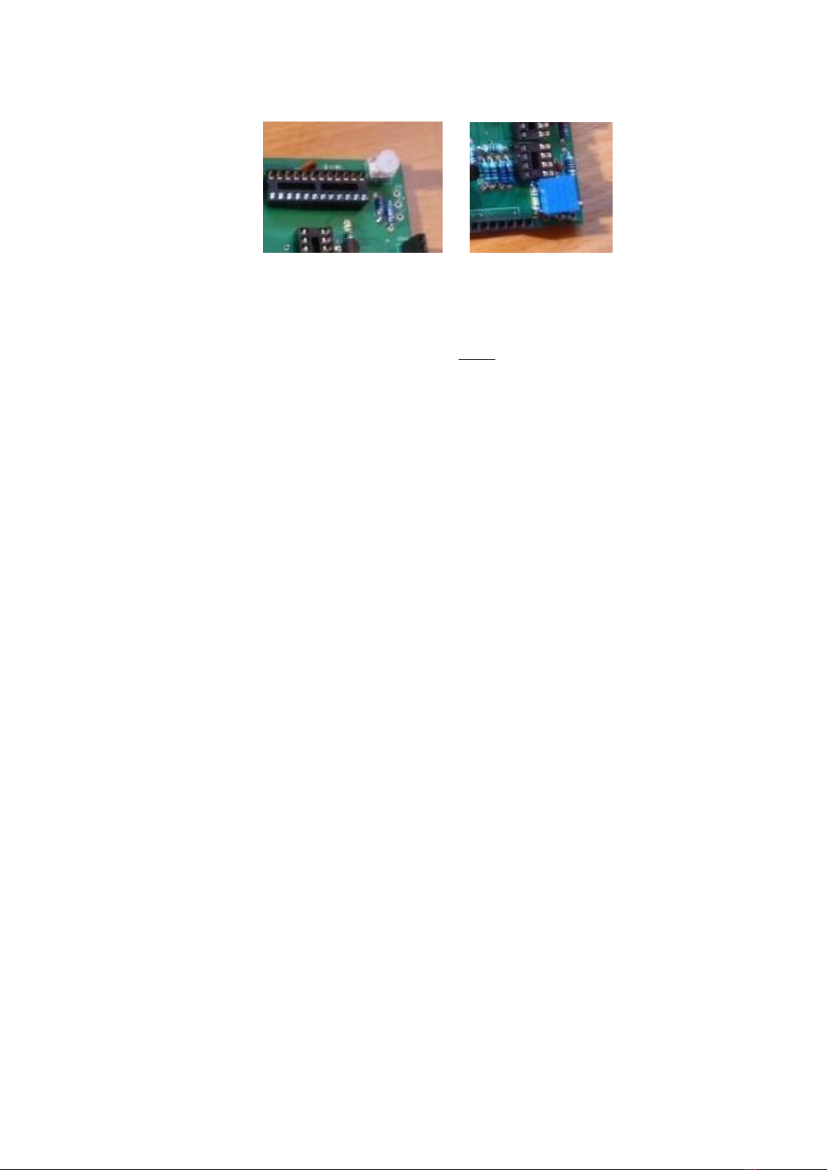
On the BACK of the PCB, solder pin 1 of regulator U6 to C7 where it connects to U5 pin 19.
Solder pin 2 of regulator U6 to the other pin of C7 (0V):
Solder an insulated wire from regulator U6 pin 3 (as above picture) to the anode of C3 (+12V):

Now inspect the main PCB with a magnifier for any unintentional solder bridges or whiskers.
Check for any shorts across the power rails.
Check for 0V continuity from the power connector to:
U3 pin 7
U4 pin 19
U5 pin 4 and pin 9
Connect the main PCB to Eurorack power: check for +12V, -12V, and +5V at the correct IC
pins
o+12V (it will be approximately 11.75V due to the power protection diode)
U1 pin 8
o-12V (it will be approximately -11.75V due to the power protection diode)
U1 pin 4
o+5V
U3 pin 1
U4 pin 20
U5 pin 19
Control PCB Assembly
Fit and solder the six resistors to the control PCB.
Care is needed when installing the LEDs as they are “buried” under the potentiometers:
oInstall the LEDs one at a time.
oCheck they work OK before installing –use the diode check function on a multi-
meter.
oFit with correct orientation:
If using Red/green LEDs as I did, RED is the UPPER anode (i.e. closest to the
7-segment display), GREEN is the LOWER anode.
oPush the LEDs fully down on to the PCB; otherwise they will not fit under the
potentiometers. I would recommend test fitting a potentiometer over each LED (do
not solder the potentiometer!!) before you solder the LED.

oThe LED leads are short; take care when soldering not to overheat them.
Now test the LED again, use the “diode” setting on a multi-meter to check that it is working
OK. With a multi-meter, the LEDs will glow dimly.
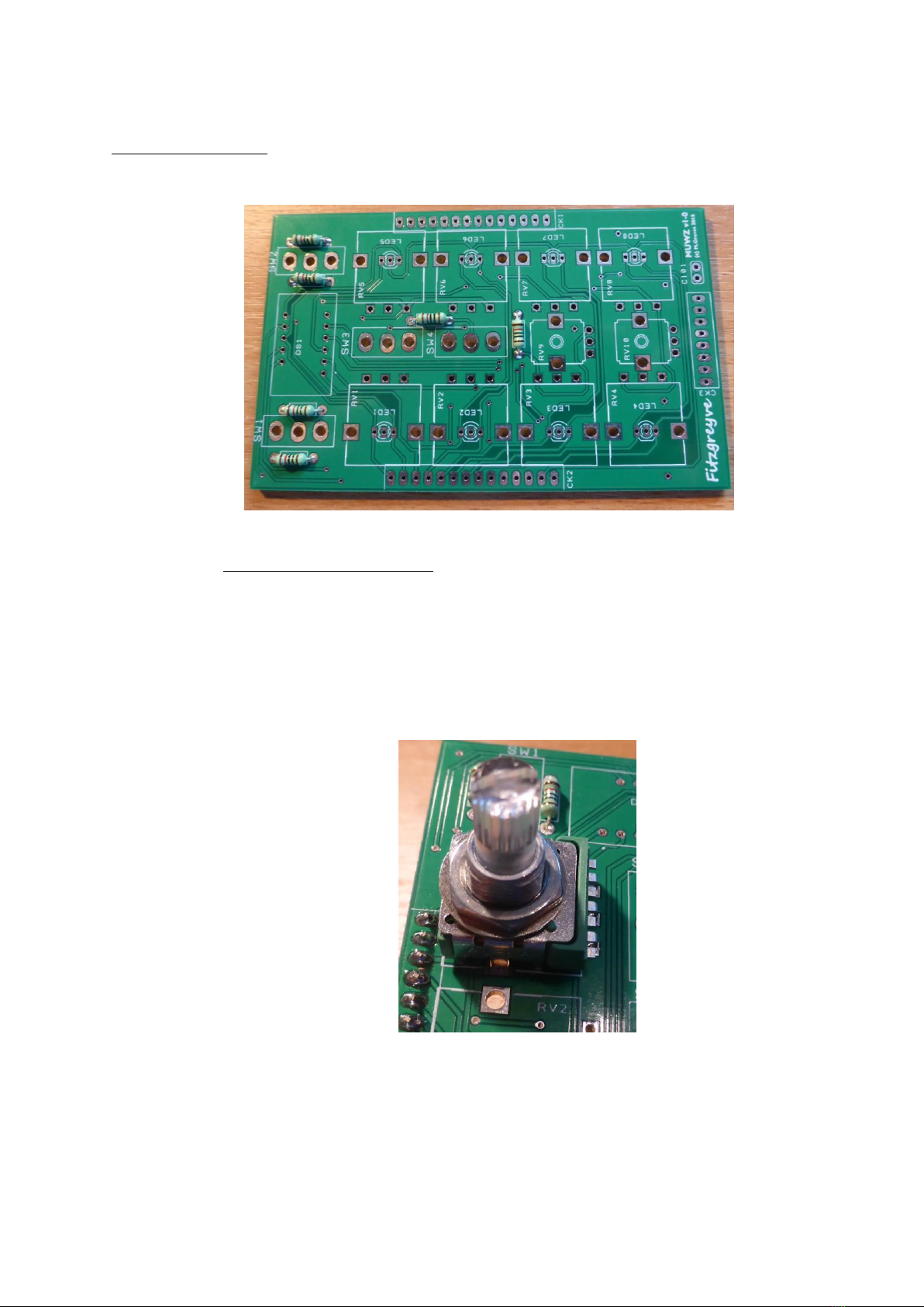
oThe centre pin on each LED is the cathode, the outside pins are the anodes.
With all LEDs fitted the PCB should now look like (this is my prototype with C101 and the SIL
connectors already fitted):
Table of contents


