fivep lite MATRIX 1 User manual

OTTICA
OPTICS
POTENZA –POWER
230 ÷ 240V
M
T
M
D
S
T
S
D
PORTALAMPADA
LAMP HOLDER
PESO
WEIGHT
60W
70W
140W
150W
250W
MATRIX
1
ROTOSIMMETRICA
CIRCULAR
X
(X)
X
G12
Kg.7 (Kg. 5.2)
SIMMETRICA
SYMMETRICAL
X
X
X
RX7s
Kg.7
ASIMMETRICA
ASYMMETRICAL
X
X
X
RX7s
Kg.7
MATRIX
2
ROTOSIMMETRICA
CIRCULAR
X
X
X
X
X
X
X
E27; G12; G22; PGZ 12;
Kg.13
SIMMETRICA
SYMMETRICAL
X
X
X
X
X
X
X
X
X
E27; RX7s-24; G22; PGZ 12;
Kg.13
ASIMMETRICA
ASYMMETRICAL
X
X
X
X
X
X
X
X
X
E27; RX7s-24; G22; PGZ 12;
Kg.13
D
D
IP66
CL. II
4
1m
3
10
SCx MATRIX 1:
Frontale : 0,075 m²
Laterale : 0.068 m²
MATRIX 1 - MATRIX 2
SOSTITUZIONE LAMPADA :
LAMP REPLACEMENT :
REMPLACEMENT DE LA LAMPE :
AUSWECHSLUNG DER LAMPE :
SUSTITUCIÓN DE LA LÁMPARA:
Allentare le 4 viti imperdibili di
fissaggio del telaio vetro, (Fig.
A) tirare il telaio in avanti (Fig.
B) e aprirlo di circa 180°, (Fig.
C) spostare la cerniera verso
destra inserendola nella
apposita sede di blocco, come
nella figura (Fig. D).
Loosen the 4 safety fastening
screws of the glass frame
(Pict. A), pull the frame
forward (Pict. B) and open it
until 180° approx., (Pict. C).
Move the hinge to right,
putting it into the special lock
slot (Pict. D).
Desserrer les 4 vis de securité
du cadre/verre (Fig. A),
avancer le cadre (Fig. B) et
l’ouvrir jusqu’à apres 180°,
(Fig. C). Deplacer la charnière
vers droite, en l’insérant dans
le spécial siège du blocage,
selon la (Figure D).
Locken Sie die 4 unverlierbaren
Schrauben, die den Glasrahmen
befestigen. (Bild A) Ziehen Sie den
Glasrahmen vor,(Bild B) und es bis
180° öffnen, (Bild C), rücken Sie das
Scharnier rechts, um es in in den dazu
bestimmten Schlitz einzuwerfen, wie
im (Bild D).
Aflojar los 4 tornillos imperdibles que
fijan el marco del vidrio (Fig.A) tirar el
marco hacia delante (Fig.B) y abrirlo
casi 180º, (Fig.C) apartar la visagra
hacia la derecha inseriendola en la
sede del bloequeo, como en la figura
(Fig.D)
I
F
F
E
GB
D
COD. 207083320 (10.10.06) 1/4
(X) SOLO CON CABLAGGIO ESTERNO
(X) ONLY WITH EXTERNAL WIRING
SCx MATRIX 1:
Frontal : 0,075 m²
Lateral : 0.068 m²
SCx MATRIX 2:
Frontal : 0,13 m²
Lateral : 0.11 m²
SCx MATRIX 2:
Frontale : 0,13 m²
Laterale : 0.11 m²

Inserire nel pressacavo l’
apposito gommino (1).
Inserire il cavo di linea
attraverso il pressacavo M20
e farlo uscire dall’ apposita
fessura (Fig. E).Collegare il
cavo di linea al morsetto
fissato sul corpo.
Insert the apposite rubber cap
into the cable gland (1).
Insert the supply cable into the
M20 cable gland and let it go
out from the special fissure
(Pict. E). Connect the supply
cable to the terminal block
fixed on the body.
Einstecken Sie die Gummi in die
Klemme (1).
Stecken Sie das Leitungkabel in die
M20 Klemme und es von den
bestimmten Schlitz hinausgehen
lassen (Bild E). Verbinden Sie das
Leitungkabel mit dem auf dem
Körper befestigten Klammer.
Insertar en el presastopa el
appropiado caucho pequeno (1).
Meter el cable de linea a través del
presestopa M20 y hacerlo salir por
laranura (Fig.E). Conectar el cable de
linea a la regleta que está fijada al
cuerpo (Fig.H).
Inserer la garniture de gomme
entre le presse-étoupe (1).
Introduire le cable d’alimentation
dans le presse-étoupe M 20 et le
faire sortir de la spéciale fissure
(Fig. E). Connecter le cable de
ligne au bornier fixé sur le corps.
I
F
F
E
GB
D
REGOLAZIONE LAMPADA:
LAMP ADJUSTEMENT:
REGLAGE DE LA LAMPE:
LAMPE REGELUNG:
REGULAZIÓN DE LA LÁMPARA:
Nel Matrix rotosimmetrico e’
possibile regolare il fuoco della
lampada. Svitare le 4 viti
imperdibili del coperchio
posteriore (Fig. F), Allentare le 3
viti di blocco del portalampada
(Fig. G-2),ora tramite le tre viti di
regolazione (Fig. G -1) e’ possibile
effettuare uno spostamento
assiale di ± 5 mm avanti o indietro
(Fig. H).Una volta definita la
nuova posizione avvitare le viti di
blocco (Fig. I-2) fino a quando non
appoggeranno di nuovo sul fondo
del corpo vano ottico.
As far as rotosymetric Matrix is
concerned, it is possible to adjust
the lamp focus. Unscrew the 4
safety screws of the back cover
(Pict. F). Loosen the 3 blocking
screws of the lamp-holder (Pict.
G-2); it is now possible, through
the 3 adjustement screws (pict.
G-1), to have an axial movement
of ± 5 mm forward or backward.
Once the new position is defined,
screw the blocking screws (Pict.
I-2) till they lay again on the
bottom of the optic compartment.
Pour ce qui concerne le Matrix
rotosymétrique, il y a la possibilité
de régler le feu de la lampe.
Dévisser les 4 vis de securité du
capot arrière (Fig. F), desserrer
les 3 vis qui bloquent le porte-
douille (Fig. G-2). Maintenant,
grace aux 3 vis de réglace, il est
possible de déplacer la douille en
sens axial de ± 5 mm en avant ou
en arrière (Fig. H). Une fois que la
nouvelle position est definée,
visser les vis de blocage (Fig. I-2)
jusqu’au moment ou elles
s’appuyent de nouveau sur le fond
dans l’ouverture optique.
En el matrix rotosimétrico es
posible reglar el foco de la
lámpara. Aflojar los 4 tornillos de
la tapa del proyector. (Fig.F).
Aflojar los 3 tornillos del bloque
del portalámparas (Fig.G-2),
ahora a través de los 3 tornillos
de regulación (Fig.G-1) es posible
hacer un movimiento axial de ± 5
mm adekante o atrás (Fig.H). Una
vez definida la nueva posición
apretar los tornillos del bloque
(Fig.I-2) hasta que apoyen de
nuevo en el cuerpo de la parte
óptica.
Beim rotosymmetischen Matrix,
ist es möglich den Focus zu
regulieren. Lösen Sie die 4
unverlierbaren Schrauben des
hinteres Deckels (Bild F) und die
3 Blockschrauben der
Lampenfassung lockern (Bild G-
2). Jetzt ist es möglich eine
Achsenverlagerung von ± 5 mm
nach vorne oder ruckwärts zu
haben (Bild H). Einmal die neue
Aufstellung entschieden worden
ist, schrauben Sie die
Blockschrauben an (Bild I-2), bis
Sie nochmal am Boden des
Körpers der optischen Öffnung
liegen.
I
F
F
E
GB
D
COD. 207083320 (10.10.06) 2/4
COLLEGAMENTO PROIETTORE :
FLOODLIGHT CONNECTION :
CONNETION DU PROJECTEUR :
VERBINDUNG DES STRAHLERS :
CONNEXIÓN PROYECTOR:

Fig. L
0,5 m
90°
90°
Fig. N
POSIZIONAMENTO APPARECCHIO :
FLOODLIGHT HOUSING:
POSITIONNEMENT DE L’ APPAREIL :
AUSFSTELLUNG DES GERÄTS :
POSICIONAMIENTO APARATO:
Fig. M
Grazie alla staffa regolabile in 3
diverse posizioni e’ possibile
utilizzare il proiettore anche in
luoghi dove lo spazio e’ limitato
(Fig. L) o dove ostacoli non
permettono l’ allineamento di piu’
proiettori (Fig. M).
N.B.
Esistono comunque dei
posizionamenti non corretti
per questo proiettore, che
potrebbero creare problemi o
pericoli per il proiettore o le
persone a lui vicino. Si
raccomanda pertanto di
seguire le indicazioni sopra
indicate (Fig. N).
Thanks to its 3 position-
adjustable bracket, it is possible
to install Matrix even in those
contexts where there’s just a little
space (Pict. L) or where some
obstacles do not allow the
alignement of more fixtures (pict.
M).
N.B.
There are, anyway, some
uncorrect posititons for this
floodlight, which could create
problems or dangerous
situations for the floodlight
itself or for the people
standing nearby.
It’s therefore recommended to
follow the instructions
hereunder (Pict. N).
Grace à son étier, réglable en 3
positions differentes, il y a la
possibilité d’utiliser le projecteur
aussi dans des lieux où l’espace
est limité (Fig. L) ou dans des
lieux où des obstacles
empêchent l’alignement des
plusièrs projecteurs (Fig. M).
N.B.
Afin d’eviter une installation
incorrecte du projecteur
Matrix ainsi qu’un mauvais
fonctionnement ou des
dommages aux personnes,
nous recommendons de
suivre les instruction de
montage ci dessus (Fig. N).
Dank seinem Steigbügel, der in
3 verschiedenen Lagen reguliert
werden kann, ist es möglich
Matrix zu benützen auch in
Platzen wo das Raum
beschränkt ist (Bild L), oder wo
einige Hindernisse die
Anrehiung mehren Geräten nicht
ermöglichen (Bild M).
N.B.
Es geben, auf jeden Fall,
einige unkorrekten
Aufstellungen für Matrix, die
verschiedene Probleme oder
gefärliche Situationen für das
Gerät selbst oder für die
Leuten in der Nähe
verursachen könnten. Deshalb
ist es empfehlenswert die
folgende Hinweise zu befolgen
(Bild N).
Gracias a la lira regulable en 3
diversas posiciones es posible usar
el proyector en lugares donde el
espacio es limitado (fig.L) o donde
los obtáculos no permiten usar otros
aparatos( Fig.M).
N.B.
Existe posicines no correctas para
este aparato, que pueden crear
problemas o peligro para el
aparato o las personas cercanas a
él, por lo que se aconseja usar las
indicaciones que se adjuntan
(Fig.N).
I
F
F
E
GB
D
COD. 207083320 (10.10.06) 3/4
SOL
A B C
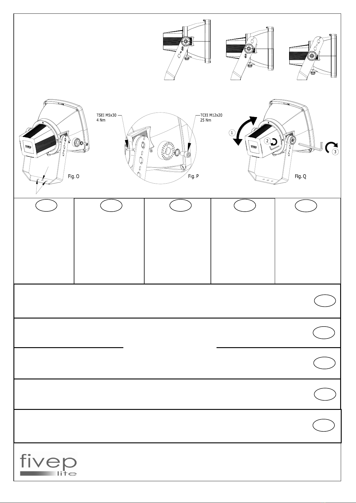
STAFFAGGIO APPARECCHIO:
FIXTURE BRACKET:
ETRIER DE FIXATION DE L’APPAREIL:
BÜGEL DES GERÄTS:
SUJECIÓN APARATO:
Fissare il proiettore
utilizzando il foro o le asole
sulla staffa (Fig. O).
Allentare le viti M5 e M12,
regolare l’apparecchio (Fig.
Q-1) e serrare le 2 viti
secondo la coppia indicata
(Fig. P) a dx e sx. Le viti
M5x30 una volta serrate
non bisogna più allentarle,
perché mantengono il
puntamento del proiettore.
Per smontare il proiettore
allentare solo le viti da
M12x20.
Fix the fitting by using the hole or
the buttonhole on the bracket
(Pict. O). Loosen screws M5 and
M12, adjust the fixture (Pict. Q-1),
and screw the scrrews as
indicated couple (Pict. P) towards
the left and the right. .
Once screws M5x30 are fixed,
they aren’t to be touched any
more, because they mantain the
floodlight sighting.
To disassemble the floodlight, just
unscrew screws M12x20.
Befestigen Sie das Gerät durch
das Loch oder das Knopfloch
auf dem Steigbügel (Bild O),
lockern Sie die Schrauben M5
und M12 und regulieren Sie das
Gerät (Bild Q-1). Blockieren Sie
dann die Schrauben rechts und
links (Bild P). Einmal die
Schrauben M5x30 fixiert worden
sind, müssen sie nicht mehr
bewegt werden, weil sie die
Richtung des Strahler halten.
Um den Strahler zu
demontieren, sollen Sie nur die
Schrauben M12x20 lockern.
Fixer l’appareil en utilisant le
trou ou les boutonnières sur
l’étrier ( Fig. O), desserrer le vis
M5 et M12, régler l’appareil
(Fig. Q-1) et bloquer bien les
vis à droite et à gauche, selon
la couple indiquée (Fig. P). Le
vis M5x30, apres leur fixage, ne
sont plus à être touchées,
parce-qu’ils mantiennent le
pointage du projecteur.
Pour désassembler le
projecteur, desserrer seulement
le vis M12x20.
Fijar el proyector uasando el
agujero de la tija (Fig.O).
Aflojar los tornillos M5 y M12,
regular el aparato(Fig. Q-1),
bloquear bien los tornillos
segundo la par indicada (Fig.P)
a la dereha y a la izquierda.
Los tornillos M5x30 una vez
bloqueados no vuelven a ser
tocados, porque mantienen el
enfoque del aparato. Para
desmontar el proyector sacar
solo los tornillos M12x20.
I
F
F
E
GB
D
Distanza minima dagli oggetti illuminati : 1 m.
Altezza d’installazione : universale.
Adatto al funzionamento in interni.
ATTENZIONE!! PERICOLO DI SCOSSA ELETTRICA, PRIMA DI EFFETTUARE OPERAZIONI DI MONTAGGIO O MANUTENZIONE TOGLIERE LA TENSIONE.
In caso di fessurazione del vetro, provvedere alla sostituzione prima di riutilizzare l’apparecchio, con un vetro di pari caratteristiche fornito dal produttore dell’apparecchio.
Adatto per impiego su superfici normalmente infiammabili.
Installare l’apparecchio avendo cura che la lampada sia in posizione indicata dalla casa costruttrice.
Minimum distance from the lightened odjects: 1 m
Installation height: universal
Suitable for indoor installation.
WARNING!! DANGER OF ELECTRICAL SHOCK, DISCONNECT THE TENSION BEFORE ANY ASSEMBLY OR HANDLING OPERATIONS.
In case of glass cracks, change it before using the floodlight, with an equal glass, purchased by the floodlight manufacturer.
Suitable for the employ on generally inflammable surfaces.
Distance minimum des objets illuminés: 1 m
Hauteur d’installation: universelle
ATTENTION!! DANGER DE CHOC ELECTRIQUE, AVANT D’EFFECTUER DES OPERATIONS DE MONTAGE OU DE MANUTENTION, DECONNECTER LA TENSION.
En cas de fissuration du verre, le remplacer avec une autre avec les mêmes characteristiques, fournie de la même maison de production
Indiqué aussi pour l’emploi sur des surfaces normalement inflammables.
Installer l’appareil en en ayant soin que la lampe soit dans la position indiquée par la maison de production.
Mindester Abstand von beleuchteten Gegenständen: 1 m
Installationshöhe: universell
ACHTUNG!! SCHLAGGEFAHR! BEVOR MONTAGE ODER UNTERHALTUNG, SPANNUNG ABNEHMEN.
Wenn der Becher sich spaltet, auswechseln es bevor das Gerät zu benützen mit ein anderem gleichwertigen Becher, vom Baufirma ausgetattet.
Geeignet auch für entzunbare Fläche.
Bei der Installation, bemerken Sie, ob die Lampe in der von der Baufirma angegebenen Lage ist.
Distancia mínima del objeto iluminado 1m
Altura de instalación: universal
Apto para interiores
ATENCIÓN!! PELIGRO DE PASO DE CORRIENTE ELÉCTRICA. ANTES DE MANIPULAR CORTAR LA CORRIENTE.
En caso de deterioro de la tapa, sustituirla antes de hacerle uso al aparato, conuna tapa similar solicitada al fabricante.
Apto para la instalación sobre superfícies normalmente inflamables.
Instalar el aparato comprobando que la posición de la lámpara es la indicada por el fabricante.
VIA DELLA TECNICA 19 VIA PRATO 22 VIA DELLA TECNICA 19
I-23875 OSNAGO (LC) I-38068 ROVERETO (TN) I-23875 OSNAGO (LC)
TEL. 039/587506 TEL. 0464/422247 TEL. 039/9521.1
FAX 039/9520006 FAX 0464/430393 FAX 039/587812
COD. 207083320 (10.10.06) 4/4
I
F
F
E
GB
D
MATRIX 1 - 2
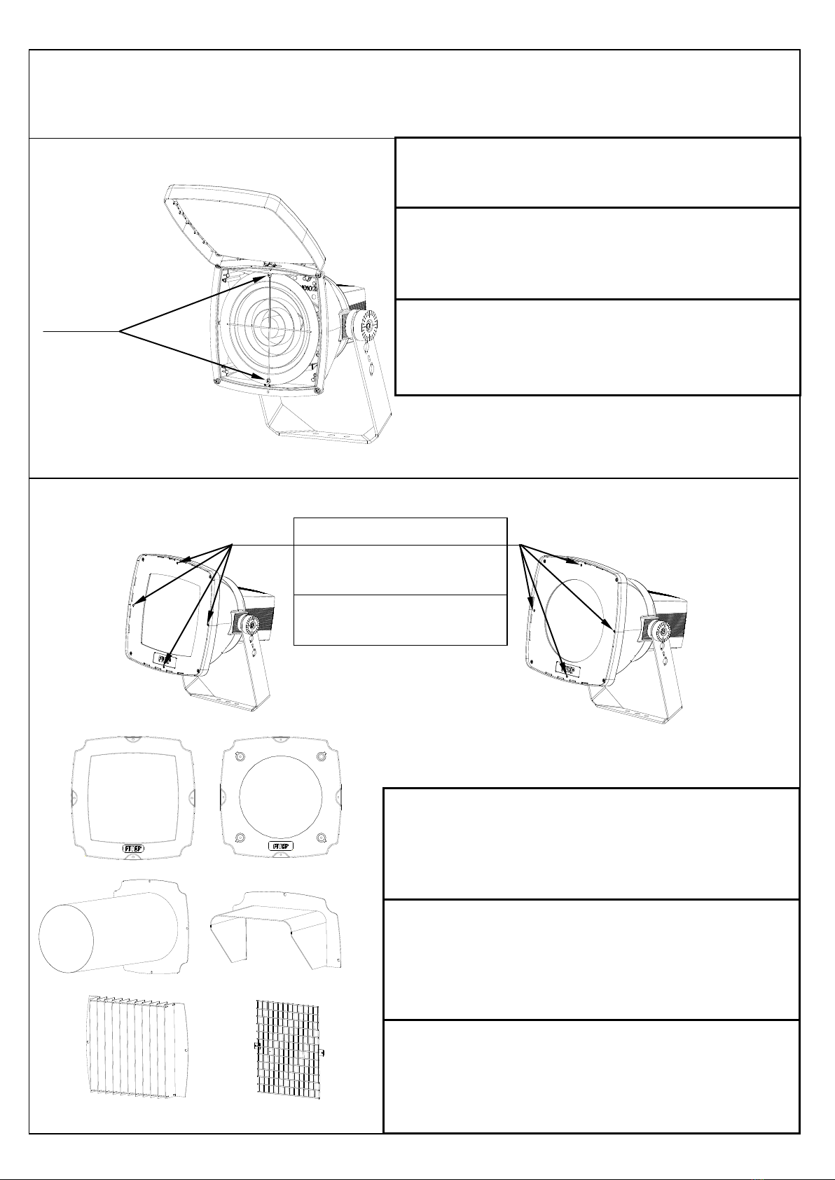
ACCESSORI ESTERNI E INTERNI
FISSAGGIO ACCESSORI
Fig. A
L’astronomico viene montato all’ interno del proiettore.
Utilizzare le due viti a croce che fissano il riflettore.
(Fig. A)
N° 2
ISTRUZIONI DI FISSAGGIO ACCESSORI ESTERNI :
Gli accessori esterni vanno montati sul telaio utilizzando
le viti a brugola M5.Ogni accessorio ha sulla base dei fori
che corrispondono ad altrettanti fori sul telaio a cui vanno
fissati.
The astronomic interior device has to be fastened inside
the floodlight, by mean of the two cross screw which
fasten the reflector.
(Fig. A)
L’astronomique interne doit être fixé à l’ìinterieur du
projecteur, en utilisant les deux vis à croix qui fixent le
reflecteur
(Fig. A)
ACCESSORIES
FASTENING
FIXATION DES
ACCESSOIRES
MOUNTING INSTRUCTIONS FOR EXTERNAL
ACCESSORIES:
The external accessories have to be fastened on the frame,
by mean of the allen screws M5. Each accessory is
provided on its base of the holes that match with the ones
on the frame.
INSTRUCTIONS DE MONTAGE DES ACCESSOIRES
EXTERNES:
Les accessoires externes doivent être fixés sur le cadre en
utilisant les vis Allen M5. Chaque accessoire a sur sa base
les troux qui correspondent avec les troux sur le cadre.
INTERNAL AND EXTERNAL ACCESSORIES
ACCESSOIRES INTERNES ET EXTERNES
207083321 08-03-2008
MATRIX 1 - 2

2
CONTRE-CADRES RONDES
ISTRUZIONI PER LA ROTAZIONE DELLE LENTI :
Allentare leggermente le tre viti anteriori (Fig. A-1).Utilizzare la chiave a brugola per ruotare il perno
(Fig. B ).
E’ inoltre possibile ruotare la lente utilizzando una chiave esagonale a tubo da 10 mm per il MATRIX T1,
da 13 mm per il MATRIX T2.
ROTAZIONE LENTI E VETRI RIGATI O META’ SABBIATI :
Fig. B
Fig. A
5
1
CONTROTELAI TONDI
ROUND COUNTERFRAMES
MATRIX 1 - 2
ROTATION OF THE LENSES AND OF THE RIFLED OR HALF-SANDBLASTED
GLASSES
ROTATION DES LENTILLES ET DES VERRES AVEC RAYURES OU DEMI-
SABLÉS
INTRUCTIONS FOR THE ROTATION OF THE LENSES:
Slightly unscrew the 3 front screws (Fig. A-1). Rotate the pin by mean of the Allen spanner (Fig. B).
It is also possible to rotate the lens by mean of an exagonal tubolar 10 mm spanner for the MATRIX 1 and
13mm for the MATRIX 2.
INSTRUCTIONS POUR LA ROTATION DES LENTILLES:
Devisser les 3 vis frontales (Fig. A-1). Tourner le pivot en utilisant la clé pour vis à six pans creux (Fig. B).
C’est aussi possible de tourner la lentille en utilisant une clé hexagonale tubulaire de 10mm pour le
MATRIX 1 et 13mm pour le MATRIX 2.
207083321 08-03-2008
This manual suits for next models
1
Popular Lighting Equipment manuals by other brands


Epstein-Design
Epstein-Design Light star trio 80/110/140 G13 manual

Command Light
Command Light Knight Series manual

DE MAJO
DE MAJO T1 Assembly instructions

HEPER
HEPER GOLEDO LT2037.760-US Installation & maintenance instructions

LITETRONICS
LITETRONICS EB40 installation instructions

COEF
COEF MP 700 ZOOM operating instructions