FK-Lightplanes FK 9 Mk IV User manual

AIRCRAFT MAINTENANCE
MANUAL
FK 9 Mk IV / Mk V ELA
Certified as Ultralight Aircraft according to
BFU 95 / LTF-UL 2003
Kennblatt Nr. 61102.1 and Nr. 61102.2
(Germany)
Type Certificate: US-SLSA
Model: FK9 Mk IV FK9 Mk V ELA
Serial Number:
Registration :
Date of manufacture:
Manufacturer and exclusive Distributor:
FK-Lightplanes Krosno - Poland
Design Organisation and Owner of IP Rights:
B & F Technik Vertriebs GmbH Speyer –Germany
document code: des.003
revision date: 01.of november 2013

document code: des.003
Design organization, owner of IP rights and customer support:
B & F Technik Vertriebs GmbH Speyer - Germany
Anton-Dengler-Str. 8
D-67346 Speyer
Phone:+49(0)6232 / 720 76
Fax:+49(0)6232/720 78
E-mail:info@fk-lightplanes.com
Service / parts only via service@fk-lightplanes.com
www.fk-servicecenter.com
This manual is issued by B&F Technik Vertriebs GmbH and no part of this manual may be reproduced or changed in any
manner without written consent.
Important service information/bulletins can be obtained from our service website. Check our website regularly as
automatic update by mail is not assured.
▲WARNING
Before starting any maintenance activities, read the entire Maintenance Manual carefully, as it contains
important safety-relevant information. Failure to do so may void warranty or cause serious personal injury or
death!
Please pay attention to the following reoccurring symbols, warning, caution and note, which you will find throughout the
maintenance manual. These symbols/signs indicate special safety guidelines and therefore are of high importance.
▲WARNING: Instructions, which if not followed, may cause serious injury or death.
█CAUTION: This section describes an instructions which if not followed, may result in
damage to the aircraft or could void warranty.
Note: Proposal for better handling, useful recommendations or durability
We appreciate critical observations, suggestions, ideas and other feedback concerning the maintenance manual.
We would like to thank our customers and users, who have sent suggestions and requirements for further development.

Maintenance Manual FK 9
B&F Technik Vertriebs GmbH
Revision 2
Section 0 Introduction
page 1
document code: des.003
TABLE OF CONTENTS
0. INTRODUCTION....................................................................................................................................... 0-6
0.1. Revisions..................................................................................................................................... 0-6
0.2. Record of Revisions................................................................................................................... 0-6
0.3. List of effective Pages................................................................................................................ 0-7
1. GENERAL................................................................................................................................................. 1-1
1.1. Equipment List............................................................................................................................ 1-1
1.1.1. Placards.................................................................................................................................... 1-2
1.1.2. Instrument Markings ................................................................................................................. 1-2
1.2. Sources to purchase Parts........................................................................................................ 1-2
1.3. List of disposable replacement parts....................................................................................... 1-3
1.4. Engine specifications................................................................................................................. 1-3
1.4.1. Power Plant Limitations ............................................................................................................ 1-3
1.5. Weight and Balance ................................................................................................................... 1-4
1.5.1.Abbreviations and Terminology ................................................................................................ 1-4
1.5.2. Basic Empty Weight.................................................................................................................. 1-4
1.5.3. Weighing................................................................................................................................... 1-5
1.5.4. Required Tools.......................................................................................................................... 1-5
1.5.5. Parts/materials required............................................................................................................ 1-5
1.5.6. Level of maintenance................................................................................................................ 1-5
1.5.7. Certification required................................................................................................................. 1-5
1.6. Tire Inflation Pressure................................................................................................................ 1-6
1.7. Approved Oils and Capacities................................................................................................... 1-6
1.7.1. Oil.............................................................................................................................................. 1-6
1.7.2. Fuel........................................................................................................................................... 1-6
1.7.3. Coolant...................................................................................................................................... 1-6
1.7.4. Brake Fluid................................................................................................................................ 1-6
1.8. Recommended Fastener Torque Values.................................................................................. 1-7
1.9. General Safety Information........................................................................................................ 1-7
1.10. Instructions for Reporting ......................................................................................................... 1-7
2. INSPECTIONS .......................................................................................................................................... 2-1
2.1. Inspections.................................................................................................................................. 2-1
2.1.1. Required Tools.......................................................................................................................... 2-1
2.1.2. Parts/materials required............................................................................................................ 2-1
2.1.3. Level of maintenance................................................................................................................ 2-1
2.1.4. Certification required................................................................................................................. 2-1
2.2. General Advice ........................................................................................................................... 2-1
2.3. Regular Maintenance and Lubrication Schedule.................................................................... 2-2

Maintenance Manual FK 9
B&F Technik Vertriebs GmbH
Revision 2
Section 0 Introduction
page 2
document code: des.003
2.4. Hard Landing Inspection ........................................................................................................... 2-3
2.4.1. Required Tools.......................................................................................................................... 2-3
2.4.2. Parts/materials required............................................................................................................ 2-3
2.4.3. Level of maintenance................................................................................................................ 2-3
2.4.4. Certification required................................................................................................................. 2-3
2.4.5. Nose landing gear..................................................................................................................... 2-3
2.5. Time between Overhaul (TBO) .................................................................................................. 2-4
3. STRUCTURES.......................................................................................................................................... 3-1
3.1. Ground Handling ........................................................................................................................ 3-1
3.2. Cleaning....................................................................................................................................... 3-1
3.2.1. Required Tools.......................................................................................................................... 3-1
3.2.2. Parts/materials required............................................................................................................ 3-1
3.2.3. Level of maintenance................................................................................................................ 3-1
3.2.4. Certification required................................................................................................................. 3-1
3.2.5. Painted Surfaces....................................................................................................................... 3-1
3.2.6. Windshield and Windows.......................................................................................................... 3-2
3.2.7. Engine and Engine Cowling...................................................................................................... 3-2
3.2.8. Upholstery and Interior.............................................................................................................. 3-2
3.2.9. Propeller.................................................................................................................................... 3-2
3.2.10. Wheels................................................................................................................................... 3-2
3.3. Wing & Struts Removal / Installation........................................................................................ 3-3
3.3.1. Required Tools.......................................................................................................................... 3-3
3.3.2. Parts required............................................................................................................................ 3-3
3.3.3. Level of maintenance................................................................................................................ 3-3
3.3.4. Certification required................................................................................................................. 3-3
3.3.5. Instructions................................................................................................................................ 3-3
3.4. Fuselage Interiors............................................................................................................................. 3-4
3.4.1. Required Tools.......................................................................................................................... 3-4
3.4.2. Parts required............................................................................................................................ 3-4
3.4.3. Level of maintenance................................................................................................................ 3-4
3.4.4. Certification required................................................................................................................. 3-4
3.4.5. Dismantling interiors and seats................................................................................................. 3-4
3.5. Landing Gear .................................................................................................................................... 3-5
3.5.1. Landing Gear Description......................................................................................................... 3-5
3.5.2. Required Tools.......................................................................................................................... 3-5
3.5.3. Parts/materials required............................................................................................................ 3-5
3.5.4. Level of maintenance................................................................................................................ 3-5
3.5.5. Certification required................................................................................................................. 3-5
3.6. Flight Controls.................................................................................................................................. 3-6
3.6.1. General ..................................................................................................................................... 3-6
3.6.2. Required Tools.......................................................................................................................... 3-6
3.6.3. Parts required............................................................................................................................ 3-6
3.6.4. Level of maintenance................................................................................................................ 3-6
3.6.5. Certification required................................................................................................................. 3-6
3.6.6. Rudder ...................................................................................................................................... 3-7
3.6.7. Flaps and ailerons..................................................................................................................... 3-8
3.6.8. Elevator..................................................................................................................................... 3-9
3.6.9. Trim System............................................................................................................................ 3-10

Maintenance Manual FK 9
B&F Technik Vertriebs GmbH
Revision 2
Section 0 Introduction
page 3
document code: des.003
3.7. Control Surface Deflection ...................................................................................................... 3-10
3.8. Jacking / Towing / Storage ...................................................................................................... 3-10
3.8.1. Jacking.................................................................................................................................... 3-10
3.8.2. Towing..................................................................................................................................... 3-11
3.8.3. Flyable Storage....................................................................................................................... 3-12
3.8.4. Temporary Storage................................................................................................................. 3-12
3.8.5. Indefinite Storage.................................................................................................................... 3-13
4. ENGINE..................................................................................................................................................... 4-1
4.1. Inspections.................................................................................................................................. 4-1
4.1.1. Required Tools.......................................................................................................................... 4-1
4.1.2. Parts required............................................................................................................................ 4-1
4.1.3. Level of maintenance................................................................................................................ 4-1
4.1.4. Certification required................................................................................................................. 4-1
4.2. General ........................................................................................................................................ 4-1
5. FUEL SYSTEM.......................................................................................................................................... 5-1
5.1. Inspections.................................................................................................................................. 5-1
5.1.1. Required Tools.......................................................................................................................... 5-1
5.1.2. Parts required............................................................................................................................ 5-1
5.1.3. Level of maintenance................................................................................................................ 5-1
5.1.4. Certification required................................................................................................................. 5-1
5.1.5. Option 1: Fuselage Tanks......................................................................................................... 5-2
5.1.6. Additional flexible Wing tanks................................................................................................... 5-3
5.1.7. Option 2: Wing Tanks: .............................................................................................................. 5-4
5.1.8. Fuel Low Pressure Warning...................................................................................................... 5-6
5.1.9. Fuel Quantity Indication ............................................................................................................ 5-6
5.1.10. Maintenance.......................................................................................................................... 5-6
5.1.11. Fuel Filter Removal and Installation...................................................................................... 5-6
5.1.12. Electrical Fuel Pump Removal and Installation..................................................................... 5-7
6. PROPELLER............................................................................................................................................. 6-1
6.1. Inspections.................................................................................................................................. 6-1
6.1.1. Adjusting of angle of attack....................................................................................................... 6-1
6.1.2. Required Tools.......................................................................................................................... 6-2
6.1.3. Parts required............................................................................................................................ 6-2
6.1.4. Level of maintenance................................................................................................................ 6-2
6.1.5. Certification required................................................................................................................. 6-2
7. FUSELAGE, INTERIOR AND UTILITY SYSTEMS.................................................................................. 7-1
7.1. Rescue system ........................................................................................................................... 7-1
7.2. Baggage....................................................................................................................................... 7-1
7.3. Doors ........................................................................................................................................... 7-1
7.3.1. Removal and Installation........................................................................................................... 7-1
7.3.2. Required Tools.......................................................................................................................... 7-2
7.3.3. Parts/materials required............................................................................................................ 7-2
7.3.4. Level of maintenance................................................................................................................ 7-2
7.3.5. Certification required................................................................................................................. 7-2

Maintenance Manual FK 9
B&F Technik Vertriebs GmbH
Revision 2
Section 0 Introduction
page 4
document code: des.003
7.4. Windscreen and Windows......................................................................................................... 7-2
7.5. Hydraulic brake system ............................................................................................................. 7-3
7.5.1. Brake bleeding.......................................................................................................................... 7-4
7.5.2. Required Tools.......................................................................................................................... 7-4
7.5.3. Parts required............................................................................................................................ 7-4
7.5.4. Level of maintenance................................................................................................................ 7-4
7.6. Heating and Ventilation.............................................................................................................. 7-5
7.6.1. Inspections................................................................................................................................ 7-5
7.6.2. Required Tools.......................................................................................................................... 7-5
7.6.3. Parts required............................................................................................................................ 7-5
7.6.4. Level of maintenance................................................................................................................ 7-5
7.7. Parking......................................................................................................................................... 7-5
7.8. Tie-Down...................................................................................................................................... 7-6
8. INSTRUMENTS AND AVIONICS ............................................................................................................. 8-1
8.1. Instrument Panel ........................................................................................................................ 8-1
8.2. Antennas ..................................................................................................................................... 8-5
8.2.1. COM Antenna ........................................................................................................................... 8-5
8.2.2. Transponder Antenna............................................................................................................... 8-5
8.2.3. GPS Antenna............................................................................................................................ 8-5
8.3. Static and Dynamic Pressure System...................................................................................... 8-5
9. ELECTRIC................................................................................................................................................. 9-1
9.1. Description.................................................................................................................................. 9-1
9.1.1. Required Tools.......................................................................................................................... 9-1
9.1.2. Parts required............................................................................................................................ 9-1
9.1.3. Level of maintenance................................................................................................................ 9-1
9.1.4. Certification required................................................................................................................. 9-1
10.STRUCTURAL REPAIR ......................................................................................................................... 10-1
10.1. Main Structure........................................................................................................................... 10-1
10.1.1. Required Tools.................................................................................................................... 10-1
10.1.2. Parts required...................................................................................................................... 10-1
10.1.3. Level of maintenance .......................................................................................................... 10-1
10.1.4. Certification required ........................................................................................................... 10-1
10.2. Subsidiary Structure ................................................................................................................ 10-1
10.2.1. Required Tools.................................................................................................................... 10-1
10.2.2. Parts required...................................................................................................................... 10-1
10.2.3. Level of maintenance .......................................................................................................... 10-1
10.2.4. Certification required ........................................................................................................... 10-1

Maintenance Manual FK 9
B&F Technik Vertriebs GmbH
Revision 2
Section 0 Introduction
page 5
document code: des.003
11.PAINTING AND COATINGS................................................................................................................... 11-1
11.0.1. Required Tools.................................................................................................................... 11-1
11.0.2. Parts required...................................................................................................................... 11-1
11.0.3. Level of maintenance .......................................................................................................... 11-1
11.0.4. Certification required ........................................................................................................... 11-1
11.1. Preparation Procedures........................................................................................................... 11-1
11.1.1. Preparation of Metal............................................................................................................ 11-1
11.1.2. Preparation of Composites.................................................................................................. 11-1
11.1.3. Preparation of Fabric........................................................................................................... 11-1
11.2. Painting...................................................................................................................................... 11-2
11.2.1. Primer.................................................................................................................................. 11-2
11.2.2. Final Coat............................................................................................................................ 11-2
12.ANNEX .................................................................................................................................................... 12-1
12.1. Airplane Registration Card...................................................................................................... 12-1
12.2. Warranty claim report .............................................................................................................. 12-2
13.FEEDBACK FORM................................................................................................................................. 13-1

Maintenance Manual FK 9
B&F Technik Vertriebs GmbH
Revision 2
Section 0 Introduction
page 6
document code: des.003
0. Introduction
0.1.
Revisions
The owner/operator is responsible for keeping all pages of this manual to the revision status indicated in the table, by
exchanging the relevant pages as and when a new revision is published.
For updates regularly check the technical service site of B & F Technik Vertriebs GmbH.
This revision information page shall be filed behind the checklist for amendments for about 6 month in order to get at a
glance all the changes that became effective during this time.
Index/Page
remove REV
insert REV
Remark / Reason for REV
all
all
REV 2
several editorial changes due to authorities request
0.2.
Record of Revisions
The fact of having inserted revised pages shall be confirmed in the list below.
Revision
inserted
Revision
inserted
No.
of
by --- on
No.
of
by --- on
FE
--
--
REV 1
1.Dec.2012
KR 1.Dec.2012
REV 2
1.Nov.2013

Maintenance Manual FK 9
B&F Technik Vertriebs GmbH
Revision 2
Section 0
page 7
document code: des.003
0.3.
List of effective Pages
Date: 1. of November 2013
Page
Revision
Date
Page
Revision
Date
Page
Revision
Date
0-1
Rev 2
01.11.13
0-2
Rev 2
01.11.13
0-3
Rev 2
01.11.13
0-4
Rev 2
01.11.13
0-5
Rev 2
01.11.13
0-6
Rev 2
01.11.13
0-7
Rev 2
01.11.13
1-1
Rev 2
01.11.13
1-2
Rev 2
01.11.13
1-3
Rev 2
01.11.13
1-4
Rev 2
01.11.13
1-5
Rev 2
01.11.13
1-6
Rev 2
01.11.13
1-7
Rev 2
01.11.13
2-1
Rev 2
01.11.13
2-2
Rev 2
01.11.13
2-3
Rev 2
01.11.13
2-4
Rev 2
01.11.13
3-1
Rev 2
01.11.13
3-2
Rev 2
01.11.13
3-3
Rev 2
01.11.13
3-4
Rev 2
01.11.13
3-5
Rev 2
01.11.13
3-6
Rev 2
01.11.13
3-7
Rev 2
01.11.13
3-8
Rev 2
01.11.13
3-9
Rev 2
01.11.13
3-10
Rev 2
01.11.13
3-11
Rev 2
01.11.13
3-12
Rev 2
01.11.13
3-13
Rev 2
01.11.13
4-1
Rev 2
01.11.13
4-2
Rev 2
01.11.13
4-3
Rev 2
01.11.13
5-1
Rev 2
01.11.13
5-2
Rev 2
01.11.13
5-3
Rev 2
01.11.13
5-4
Rev 2
01.11.13
5-5
Rev 2
01.11.13
5-6
Rev 2
01.11.13
5-7
Rev 2
01.11.13
6-1
Rev 2
01.11.13
6-2
Rev 2
01.11.13
7-1
Rev 2
01.11.13
7-2
Rev 2
01.11.13
7-3
Rev 2
01.11.13
7-4
Rev 2
01.11.13
7-5
Rev 2
01.11.13
7-6
Rev 2
01.11.13
8-1
Rev 2
01.11.13
8-2
Rev 2
01.11.13
8-3
Rev 2
01.11.13
8-4
Rev 2
01.11.13
8-5
Rev 2
01.11.13
9-1
Rev 2
01.11.13
10-1
Rev 2
01.11.13
11-1
Rev 2
01.11.13
11-2
Rev 2
01.11.13
12-1
Rev 2
01.11.13
12-2
Rev 2
01.11.13
13-1
Rev 2
01.11.13


Maintenance Manual FK 9
B&F Technik Vertriebs GmbH
Revision 2
Section 1 General
page 1
document code: des.003
1.
General
This manual must be read carefully by the owner and operator in order to become familiar with the maintenance of the
FK 9 Mk IV and Mk V (ELA). The manual presents suggestions and recommendations to help obtain safe and maximum
performance without sacrificing economy. It does not replace procedures or limitations mentioned in the Pilot’s Operating
Handbook (POH)!
The owner and operator should also be familiar with the applicable aviation regulations concerning operation and
maintenance of his airplane.
All limits, procedures, safety practices, servicing, and maintenance requirements contained in this manual are considered
mandatory to keep the airplane airworthy.
All values in this manual are based on ICAO Standard Atmosphere conditions and maximum take-off weight (MTOW).
The pilot in command shall make sure that the airplane is airworthy and operated according to this manual.
1.1.
Equipment List
The following shows a list of the standard equipment for the FK9 Mk IV and FK9 Mk V (ELA). A current list with optional
equipment can be found on the FK-Lightplanes webpage. The ballistic recovery system (BRS) is not required by law in
every country and is therefore not part of the standard equipment.
Note:
For weight and balance it is mandatory to list all installed equipment.
Standard FK9 MK IV equipment:
basic instruments: speed indicator, altimeter (5000ft), compass,
slip indicator, oil pressure and oil temperature, cylinder head temperature (CHT), rpm indicator, Junkers 3-blade
propeller.
hydraulic disc brake 6" main wheel system with park lock
fiberglass seats with two color upholstery
oil-inspection cap integrated in engine cowl
side air vents in both cockpit doors
mechanical elevator trim, electrical flap position indicator
60l fuselage fuel tank with electric level indicator and drain vent
electric fuel booster pump and fuel pressure warning
single color white with standard decoration
Standard FK9 ELA equipment:
basic instruments: speed indicator, altimeter (5000ft), compass,
slip indicator, oil pressure and oil temperature, CHT, rpm indicator, Junkers 3-blade prop.
hydraulic disc brake 6" main wheel system with park lock
fiberglass seats with two color upholstery
seatrests adjustable in position and angle
oil-inspection cap integrated in engine cowl
side air vents in both cockpit doors
mechanical elevator trim, electrical flap position indicator
60l fuselage fuel tank with electric level indicator and drain vent
electric fuel booster pump and fuel pressure warning
additional pockets on both cockpit sidewalls
electrically operated flaps
luggage compartment with external access door
additional aerodynamic fairing set for wing strut nose and intersections
electric multi-information display (MID)

Maintenance Manual FK 9
B&F Technik Vertriebs GmbH
Revision 2
Section 1 General
page 2
document code: des.003
1.1.1.
Placards
Refer to the respective POH
Location:
Placard:
In the Cockpit
max. TOW ............. kg
spins and acrobatics prohibited
Cockpit
Weighing date:
Empty weight:
Poss. load including fuel:
Cockpit rear section
Type placard (metal)
Door handles (inside + outside)
OPEN / CLOSE
Fuel selector in flow direction
Fuel
Fuel selector closed position
Close
Aft baggage compartment
max. load 15 kg with 60L fuel
Choke (ROTAX only)
Choke
Carburetor heat
carb. (option)
Cabin heat
cabin heat (option)
Trim handle
Trim
Trim markings
Neutral; nose up; nose down
Oil temperature indication VDO
OIL
CHT indication VDO
CHT
Fuel cap (for Rotax Version)
FUEL AVGAS / MOGAS
Fuel indication
Markings every 10l
Vicinity of rescue system
placard Rescue system
Rocket Exit Area
Danger: Rocket Exit Area
safety pin rescue system
Remove before flight
Wheel fairings main wheels
2.0 bar
Wheel fairing nose wheel
1.5 bar
Towing version only:
Vicinity of airspeed indicator
Care for tow speed !
Handle for cowl flap
Cowl flap
Handle for towing clutch
TOW
1.1.2.
Instrument Markings
Airspeed Indicator: refer to respective POH
Engine Instruments: refer to respective engine manual
1.2.
Sources to purchase Parts
Spare parts and service/support for all FK planes can be ordered from your local dealer or directly from:
B & F Technik Vertriebs GmbH Speyer
Anton-Dengler-Str. 8
D-67346 Speyer, Germany
Tel.:+49(0)6232/72076
Fax:+49(0)6232/72078
Email: [email protected]
Note:
Please use the relevant form to order spare parts.
All spare part orders are processed and delivered in the quickest possible time.
Ask your local dealer to maintain a spare parts inventory, it might be better and faster (especially outside Europe) to
purchase orders from the local FK dealer.

Maintenance Manual FK 9
B&F Technik Vertriebs GmbH
Revision 2
Section 1 General
page 3
document code: des.003
1.3.
List of disposable replacement parts
Description
Type
Engine:
ROTAX 912
oil
Shell Advance VSX 4
oil filter
Rotax 825706, gasket oil filter, gasket for oil drain
Air filter
Rotax 825551
spark plugs
Rotax NGK DCPR7E (80hp)
NGK DCPR8E (100hp)
engine shock mount
Megi Konus
exhaust-muffler support spring
Rotax
coolant
Glysantin @ 50% mixing ratio
fuel filter
MANN WK 42/2
Electric:
battery
Motorcycle battery 12V / 14Ah
12V / 16Ah, Hawker gel battery
fuses
Micro fuse 0,5- 8 A (delay action)
generator blade type fuses 20 A
Landing light bulb
12V 50W
Tail light bulb
12V 5W
Strobe light bulb
12 V 30W (Xenon) not for LED
Position light bulb
12 V 5W
Landing gear:
Nose wheel
Duro 4.00x4 4-ply
Main wheel
Sava 4.00 x 6 ply
Tundra 8.00 x 6 ply4
Tube nose wheel
4.00 x 4 with 90° valve
Tube main wheel
4.00 x 6 with 90° valve
Tundra8.00 x 6 with 90° valve
Disk brake
M.I. 42354-6
Brake pads
M.I 42176
Fuselage:
Seat cover
FK-Lightplanes
1.4.
Engine specifications
refer to the respective engine manual
Exhaust system (ROTAX):
The engine is delivered optionally with a Rotax steel or with a stainless steel exhaust system.
Note:
Based on past experience, it is recommended to install the stainless steel system because of the durability of
the product, especially in regions with high humidity.
█CAUTION:
A complete description of engines, parts, their maintenance requirements, performance and service bulletins
can be found in the manufacturer’s manuals or on the manufacturer’s webpage.
1.4.1.
Power Plant Limitations
refer to the respective engine manual
Note:
The following SB-912-036R1 has been issued for all ROTAX 912A / 912F / 912S / 914F engines:
Subject: Oil system, Engine lubrication system
Engines which have had the propeller spun for more than 1 turn in reverse direction allow air to be ingested into the
valve train.
Action:
1. It is forbidden to turn the propeller in reverse direction for more than 1 turn.
2. Inspection for correct venting of the oil system has to be performed in cases when the propeller has been spun
in reverse direction for more than 1 turn.
Maintenance Manual FK 9
B&F Technik Vertriebs GmbH
Revision 2
Section 1 General
page 4
document code: des.003
1.5.
Weight and Balance
1.5.1. Abbreviations and Terminology
Reference Datum
An imaginary vertical plane from which all horizontal distances are measured
for balance purposes
Arm
The horizontal distance from the reference datum to the center of gravity of an
item
Moment
The product of the weight of an item multiplied by its arm
Airplane center of gravity (C.G.)
The point at which an airplane would balance if suspended. Its distance from
the reference datum is found by dividing the total moment by the total weight of
the airplane
C.G. arm
The arm obtained by adding the airplane’s individual moments and dividing the
sum by the total weight
C.G. limits
The extreme center of gravity locations within which the airplane must be
operated at a given weight
Empty weight
Weight of the airplane including unusable fuel, full operating fluids and full oil;
equipment as indicated
1.5.2. Basic Empty Weight
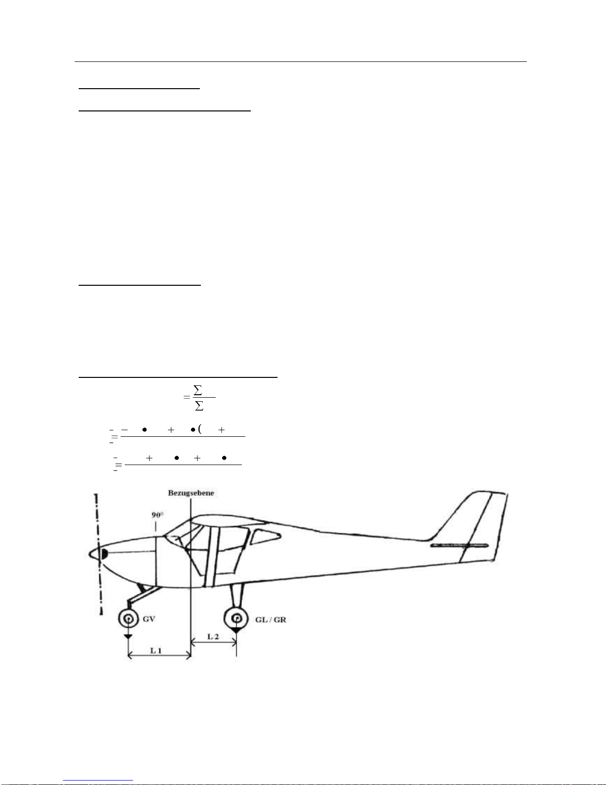
By using the following formula, the C.G. is computed. Reference line (datum) for all arms is the leading edge of the wing.
Prior to delivery, each aircraft has been weighed with the fuselage level, (reference line see drawing below), including oil
and coolant, as well as equipment as indicated but no fuel (except un-drainable fuel). During this procedure the
respective arms are determined as well.
All these data are transferred to the Basic Empty Weight and Balance Form (German: Wägebericht). This “Wägebericht”
contains a list of equipment installed and is part of the POH.
All changes to the airplane affecting weight and balance (installation of new equipment etc.) require a new weighing.
Formula to compute the center of gravity (X):
Center of Gravity in [m]
CG M
G
GG = total weight
GV = weight front
GR = weight right
GL = weight left
GG GLGRLGVL
mX )(21
Tricycle
GG LGHLGLGR
mX 21)(
Tail wheel
GH = weight aft

Maintenance Manual FK 9
B&F Technik Vertriebs GmbH
Revision 2
Section 1 General
page 5
document code: des.003
Arms (Datum: wing leading edge):
See actual Form “Wägebericht”
For the tail wheel version, following applies:
L 1 = from datum to the axle of the main wheels
L 2 = from datum to the axle of the tail wheel
1.5.3. Weighing
The best place for the weighing is inside a hangar with a flat surface and no air current. The weighing should be
performed as shown. For a correct result the plane should be rolled, if necessary over ramps onto the three weighing
scales. It is very important that the plane is not lifted on the scales. By lifting the plane on the scales the lateral forces of
the main gear spring can falsify the result. Once the plane stands on the scales, it must be checked if the firewall is
perpendicular to the floor. By inserting a plate under the front or main wheels, the plane can be aligned correctly.
█CAUTION:
The plane must be secured with the park brake to prevent rolling.
1.5.4. Required Tools
3 x weighing scales (min. measuring range for each scales 200Kg / 441 lbs.)
if necessary ramps for the scales
spirit level
plummet
tape measure
1.5.5. Parts/materials required
None
1.5.6. Level of maintenance
Line
1.5.7. Certification required
A&P Mechanic or LSA Repairman Maintenance

Maintenance Manual FK 9
B&F Technik Vertriebs GmbH
Revision 2
Section 1 General
page 6
document code: des.003
1.6.
Tire Inflation Pressure
Wheel
Size
Pressure
Main
6.00 x 6, 4.00 x 6
8.00 x 6
1.8 to 2 bar
17 –29 psi
Front
4.00 x 4
1.5 - 2 bar
21 - 29 psi
Tail
120 / 150mm
Note:
To improve the durability of the tires, you should avoid excessive solar radiation (UV radiation) as it causes
premature ageing. It is recommended to examine the tires for wear marks during pressure checking.
1.7.
Approved Oils and Capacities
1.7.1. Oil
refer to the respective engine manual
1.7.2. Fuel
Fuel capacity Option 1 Fuselage tank:
2 x fuselage fuel tank 30l (7.92 US gal.) each, 60l (15.85 US gal.) total.
Optional flexible Wing tanks (in addition to fuselage tank):
2 x wing tanks 20l (5.28 US gal.) each, 76l (10.57 US gal.) total.
Fuel capacity Option 2 Wing tank:
2 x wing tanks 38l (10 US gal.) each, 76l (20 US gal.) total
LSA optional: Long range wing tanks 2 x 55l (14.5 US gal.) each, 110l (29 US gal.) total
▲WARNING:
The values include unusable fuel!
Fuel specification:
Refer to the original corresponding chapter in the engine operator's manual.
Rotax:
AVGAS should only be used if MOGAS is not available or in case of problems caused by vapor locks.
AVGAS 100 LL
MOGAS
premium unleaded automobile fuel without bioethanol (ASTM D4814)
Smart:
Unleaded fuel, mandatory for M160 (smart)
Min. ROZ/ RON 95-Octane rating without bioethanol (unleaded fuel)
▲WARNING:
Restrictions apply for use of fuels containing methanol –see related service bulletin!
1.7.3. Coolant
approx. (ROTAX) 1.5l (0.4 US gal.)
delivered ex-factory with Glysantin Protect Plus/G48 from BASF® mixture with water 1:1
1.7.4. Brake Fluid
FMVSS 116-DOT4 - SAE J 1073
▲WARNING:
Never mix brake fluids with different DOT ratings.
Using DOT ratings not listed above can damage seals.

Maintenance Manual FK 9
B&F Technik Vertriebs GmbH
Revision 2
Section 1 General
page 7
document code: des.003
1.8.
Recommended Fastener Torque Values
The torque values set out in the table are ISO standards and should only be used as reference. All values should be
used for any installation described in the maintenance manual, unless other values are specified.
Note:
All bolts must be mounted up to down, inside to outside or front to back, unless design does not permit.
Metric Bolt Assembly Torque, Grade 8.8
Size
Wrench size mm
tightening torque in Nm
tightening torque in lbf ft.
M4
7
4
2.9
M5
8
6
4.4
M6
10
10
7.3
M8
13
24
16.9
M10
16
35
25.8
█CAUTION:
Never exceed the values set out in the tables as this will result in mechanical damage. Once you have re-
opened any lock nut, it must be replaced with new nut. Never re-use lock nuts. Bolts or nuts without any self-
locking property must be marked with thread locker.
1.9.
General Safety Information
This chapter deals with the normal procedures recommended for the safe operation of the FK 9.
▲WARNING:
Ensure that the parachute system is always secured with the safety pin.
Never leave the plane unattended with unauthorized persons especially when the engine is running.
Use caution during taxi and engine run up. Note that a foreign object can come into the danger zone of the
propeller at any time.
Never perform engine run up with full throttle on smooth surfaces without wheel chocks.
Ensure that the keys are removed and main switches and ignition switch are turned OFF during any work on the
engine and propeller.
Note:
The illustrations of this Manual show the typical construction. They may not represent in full detail or the exact
shape of the parts, which have the same or similar function.
1.10.
Instructions for Reporting
Aircraft Make, Model, Serial Number
Engine Make, Model, Serial Number
Date of Inspection
Total Time
Airframe
Engine
Color
Description of the un-airworthy items found
Owner of Aircraft


Maintenance Manual FK 9
B&F Technik Vertriebs GmbH
Revision 2
Section 2 Inspections
page 1
document code: des.003
2.
Inspections
2.1.
Inspections
Light Sport Aircraft (LSA) aircraft are designed to be lighter than normal aircraft but must withstand similar loads. The
structure and the engine must be inspected regularly to maintain airworthiness.
If there is any damage it is recommended to consult a certified maintenance facility or contact the manufacturer. This
applies especially to composite and aluminum structures.
Note:
Weather or environmental influences may negatively influence the recommended intervals. The result is a
reduction of the intervals.
2.1.1.
Required Tools
Set hexagon Allen wrench
Set screwdriver
Set metric ratchet wrench or set of metric combination wrench
Torque wrench
Oil filter wrench
Side cutters
Pliers
Safety wire twisters
2.1.2.
Parts/materials required
Metric screws and nuts
Loctite 243
Safety wire
Oil filter
Gaskets
Spark plugs
2.1.3.
Level of maintenance
Line
2.1.4.
Certification required
Owner, LSA Repairman Inspection, LSA Repairman Maintenance, A&P
2.2.
General Advice
The vibration dampers at the engine mount should be treated regularly with Vaseline to prevent aging.
Fuel lines, cables and Bowden cables must not be damaged.
█CAUTION:
For any maintenance or repair works first secure rescue system with safety pin and disconnect aircraft battery
completely from electric system.
Never turn the propeller for more than 1 turn in opposite direction (ROTAX engine)

Maintenance Manual FK 9
B&F Technik Vertriebs GmbH
Revision 2
Section 2 Inspections
page 2
document code: des.003
2.3.
Regular Maintenance and Lubrication Schedule
The following actions must be performed after certain flight hours or time intervals as applicable.
There are some actions which must be done for the first time after the very first 2 / 10 / 25 flight hours. The regular
maintenance intervals are 100 / 200 / 500 flight hours or every year / every 2 / every 4 years.
Engine maintenance is not part of this manual, it must be performed additionally according to the respective engine
manual.
Download the latest, valid updated version of the maintenance plan from the FK-Service site!
Item
Interval
Check and tighten all engine connections (oil, coolant and fuel lines)
after the first 2
hours
Check oil level
Check cooling and brake system for leaks
after the first 10
hours
Check all screws
Check the screws (tight and secured) of the main gear beam to the fuselage
Check the propeller for blade synchronization and wear at the spinner
Item
100
200
500
Check engine vibration damper for cracks and wear
X
X
X
Treat the Bowden cables with Teflon spray
X
X
X
Check the screw connection of the main gear beam to the fuselage and gear-beam for no play
Change screws every 1000 landings
X
X
X
Check the propeller for synchronization, proper connection and wear
X
X
X
Check flight controls for wear, lubrication and bearings are secured
X
X
X
Check the trim for proper operation; the friction must be high enough to assure the trim does not move
without pilots action
X
X
X
Check fuel system for leaks, contamination, dirt. Change the fuel filter
X
X
X
Check nose wheel damper for cracks and wear
X
X
X
Check tail wheel for cracks and wear. Check nose / tail wheel steering for wear, corrosion, lubrication
X
X
X
Item
100
200
500
Check flaps for no play when retracted
X
X
X
Check flap handle for correct position
X
X
X
Check tires for wear and tire pressure
X
X
X
Check brake system for wear; hydraulic disc brake only: check for leaks, change fluid every 2 years
X
X
X
Check elevator bearing bolts secured
X
X
X
ROTAX only: change carburetor flange
(with air box change required every 200 hours)
X
X
X
After 500 hours total:
check the rivets at the elevator
X
X
X
Air box: check all screws and mechanical parts tight
X
X
X
Change or clean air filter
X
Check Bowden cables of carburetors for lubrication and wear; replace every 400 hours
X
Or every 2 years: replace engine vibration damper
X
Check rudder cables for wear
X
Check bearings of flight controls and flaps for wear / play
X
Check bolts for wear and corrosion
X
Check Ceconite covered parts for condition of the skin
X
Or every 4 years: replace all rubber tubes for fuel, oil and cooling liquid
X
Lubrication Schedule
Or every year: Bearings nose-/tail wheel steering
X
X
X
Flight control linkage
X
X
X
Flight control bearings
X
X
X
Or every year: Bolts
X
X
X
Engine control cables
X
X
X
This manual suits for next models
1
Table of contents
Other FK-Lightplanes Aircraft manuals


Popular Aircraft manuals by other brands


Horejsi
Horejsi Q12 X manual

Air Creation
Air Creation FUN 450 Instruction and maintenance handbook

Carl Goldberg Models
Carl Goldberg Models Tiger 2 ARF manual

ROBBE
ROBBE SAPPHIRE 2678 Instruction and user's manual

Piel
Piel EMERAUDE CP301 VH-SJH Aircraft flight manual

Piper
Piper CHEROKEE WARRIOR PA-28-151 1995 Maintenance manual


