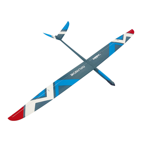
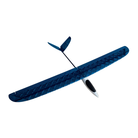
ROBBE Calif A21 S User manual

Montage- und Bedienungsanleitung
Assembly and operating instructions
Notice de montage et d´utilisation
Calif A21 S
No. 3034

Bauanleitung, Assembly instructions, Notice de montage
Calif A21 S
2
3034
No.
Technische Daten
Spannweite: ca. 4120 mm
Länge: ca. 1510 mm
Gesamtflächeninhalt: ca. 62 dm
2
Fluggewicht : ca. 5000 g
Flügelprofil: SD 7062
Nicht enthaltenes Zubehör siehe Beilageblatt
Werkzeuge und Hilfsmittel siehe robbe Hauptkatalog
Allgemeine Hinweise für den Bauablauf
Verschaffen Sie sich vor Baubeginn in Verbindung mit den
Abbildungen und den Kurztexten einen Überblick über die
Reihenfolge des Bauablaufs.
Denken Sie daran, daß Reklamationen nur vor Baubeginn
und nicht nachdem die Teile schon bearbeitet wurden, von
uns anerkannt werden können.
Wenn nicht anders erwähnt, wird mit Epoxy geklebt. Bei ver-
schiedenen Klebestellen, insbesondere beim Einbau der
Spanten, empfiehlt es sich, das Harz z. B. mit Micro-Ballons
einzudicken.
Alle Klebestellen vor dem Klebevorgang mit Schleifpapier
aufrauhen.
Das Auffinden der Stanzteile erleichtert die
Identifikationszeichnung „0“ auf Seite 5. Stanzteile entspre-
chend kennzeichnen und bohren, dann erst austrennen.
Hinweise zur Fernsteueranlage
Als Fernsteuerung benötigen Sie eine Anlage mit 9 Kanälen
und 10 Servos.
Orientieren Sie sich vor Baubeginn über die Einbaumöglich-
keit der zu verwendenden Fernsteuerung.
Sollte eine andere, als die von uns vorgeschlagene
Steuerung verwendet werden, können Sie sich nach dem
Einbauschema richten.
Maßdifferenzen sind von Ihnen selbst auszugleichen.
Caractéristiques techniques
Envergure 4120 mm environ
Longueur 1510 mm environ
Surface alaire totale 62 dm2environ
Poids en ordre de vol planeur approx. 5000 g
Profil de l’aile SD 7082
Accessoires non contenus dans la boîte de construction,
cf. le feuillet joint
Outillage et accessoires de montage, cf. Catalogue
général robbe
Recommandations générales concernant la construction
Avant d’entreprendre la construction, lire attentivement les
textes explicatifs en vous reportant aux illustrations afin de
vous faire une idée d’ensemble de l’ordre des séquences
d’assemblage.
Ne pas oublier que nous n’acceptons de réclamation qu’an-
térieurement à la construction du modèle et non pas lorsque
les pièces ont été traitées.
Sauf mention contraire, coller avec de la colle époxy. Pour
divers emplacements, particulièrement en ce qui concerne
les couples, il est recommandé d’épaissir la résine avec des
micro-ballons par exemple.
Poncer tous les emplacements destinés à recevoir de la colle
avec du papier de verre fin avant d’appliquer la colle.
L’identification des éléments estampés est facilitée par le
schéma “0” spécifique de la page 5. Repérer les éléments
estampés en conséquence et les percer avant de les détach-
er de leur support.
Recommandations concernant l’ensemble de radiocom-
mande
L’ensemble de radiocommande recommandé doit disposer
de 9 voies et être en mesure d’asservir 10 servos.
Avant d’entreprendre la construction, il faut disposer de
l’ensemble de réception afin de déterminer les possibilités
d’implantation.
Specification
Wingspan: approx. 4120 mm
Length: approx. 1510 mm
Total surface area: approx. 62 dm2
All-up weight: approx. 5000 g
Wing section: SD 7062
Please see the separate sheet for details of essential
items not included in the kit. The main robbe catalogue
contains details of tools and aids to building.
Sequence of assembly
Please read through the building instructions, referring to the
illustrations all the time, so that you have a clear idea how
the model goes together before you start building.
Bear in mind that we cannot consider complaints about any
part of the kit which you have already worked on, so check
all the components carefully right at the outset.
Epoxy is to be used for all joints in this model unless specif-
ically stated otherwise. In some cases it is advisable to thick-
en the resin with micro-balloons or similar filler powder; this
applies in particular to the joints between the bulkheads and
the fuselage.
Roughen all joint surfaces with abrasive paper before apply-
ing glue.
The identification drawing „0“ on page 5 is designed to help
you identify the die-cut parts. Mark the numbers on the die-
cut parts and drill holes at the marked points before you
separate the parts from the sheet.
Radio control system
For the Calif you will need an 9-channel radio control system
with 10 servos.
Check that your system components will fit as shown before
you start installing the equipment.

Bauanleitung, Assembly instructions, Notice de montage
Calif A21 S
3
3034
No.
Hinweis zum Einziehfahrwerk
Das Doppel-Einziehfahrwerk kann sowohl bei der Erstellung
des Modells als auch nachträglich eingebaut werden.
Notwendige Inneneinbauten sind mit vorgesehen. Bei dem
eigentlichen Einbau richten Sie sich bitte nach der
Anleitung, die dem Fahrwerk beiliegt.
Hinweise zur Bespannung beim Modell Calif ARF
Temparaturschwankungen während des Transports können
zu partiellem Verlust der Spannung der Bespannfolie führen.
Die Folie spannt sich wieder, wenn mit einem Föhn (No.
6100) Wärme zugeführt und die Folie glattgestrichen wird.
Alle Richtungsangaben wie z. B. „rechts“ sind in
Flugrichtung zu sehen.
If you intend to use RC components other than those we
recommend, you can still follow the basic arrangement
shown.
However, you may have to make allowance for minor differ-
ences in component size.
Retractable undercarriage
The twin-wheel retract unit can be installed when you build
the model, or fitted at any time subsequently; the essential
internal fittings are installed as a normal part of construc-
tion. For the actual installation please refer to the instruc-
tions which are supplied with the retract unit.
The film covering of the ARTF version of the CALIF
Temperature fluctuations in transit may cause the covering
film to slacken slightly. You can re-tighten the film by play-
ing warm air over it using a heat gun (No. 6100), rubbing the
film down smoothly as you do so.
All directions such as „right-hand“ are as seen from the
tail of the model looking forward.
Si vous choisissez un autre ensemble de radiocommande
que celui que nous conseillons, à vos d’en harmoniser les
cotes en fonction du schéma d’implantation.
Recommandations concernant l’atterrisseur
escamotable
Le double atterrisseur escamotable peut être mis en place
lors de la construction du modèle mais également par la
suite. Il faut toutefois prévoir l’aménagement intérieur en
conséquence, il est présenté dans la notice. Pour sa mise
en place, se reporter à la notice qui l’accompagne.
Recommandations concernant l’entoilage du modèle
Calif ARF
Les variations de température possibles pendant le trans-
port sont susceptibles de réduire partiellement la tension de
l’entoilage. L’entoilage retrouvera sa tension initiale si vous
le passez au sèche-cheveux (réf. 6100) en le lissant.
Les données directionnelles comme "droite", par
exemple, sont à considérer dans le sens du vol.

Bauanleitung, Assembly instructions, Notice de montage
Calif A21 S
4
3034
No.
Baukasteninhalt Calif A21 S
Menge Artikel
2 Decorbogen Schriftzüge
1 GFK-Rumpf
1 Tiefziehteil Cockpiteinsatz
1 Tiefziehteil Kabinenhaube
1 Höhenleitwerk
1 Tragfläche rechts
1 Tragfläche links
1 Seitenruder aus Balsa
Stanzbrett 3 mm Sperrholz mit folgenden Teilen:
2 Aufdoppelung für hintere Fahrwerksverstärkung
1 Hauptspant hinten
2 Seitenwand für Servorahmen
1 Servorahmen
1 Halbspant vorne
1 Längsspant
2 Abstandsleiste
2 Halteplättchen
1 Haltelasche
1 Halbspant vorne,klein
1 Schalteraufnahme
Beutel Winglet u. Seitenruderabschluß
1 Buchenrundstab ø 5 x 35
1 Winglet GFK links
1 Winglet GFK rechts
1 Seitenruderabschluß GFK
Beutel Draht, Gestänge, Führungsrohr
2 Rundstahl ø 12,1 x 250
2 Arretierungsdraht ø 3 x 50
1 Höhenrudergestänge ø 1,8 x M 2 x 20 x 250
6 Gestänge einseitig Z-gekröpft, 1,2 x 100
1 Höhenruderverbindungsgestänge Stahl ø 2 x 100
1 Messingröhrchen ø 2,5 / 1,7 x 75
1 Lagerdraht Stahl ø 1,5 x 120
1 Führungsröhrchen ø 3,2 / 2,4 x 260
1 Stahldraht ø 1 x 250
Beutel Kleinteile
1 Kugelkopf Kunststoffspritzteil
2 Befestigungsklötzchen (Abachi, 10 x 10 x 21)
1 Abdeckung oben für Seitenruder, Balsa, 3 x 5 x 140
1 Kugelbolzen ø 4,8 x 10
1 Stellring ø 2 / 7 x 5 Messing
9 Gabelkopf 26 lang M 2
9 Gewindebuchse M 2
9 Sechskantmutter M 2
9 Augbolzen M 3 x 31
2 Messinghülse ø 2,5 / 1,7 x 5
1 Litze ø 0,8 x 2500
1 Messingröhrchen ø 3 / 2,2 x20
1 Kunststoffschraube M 4 x 50
1 Kunststoffschraube M 4 x 25
2 Einnietmutter M 2,5
2 Schraube M 2,5 x 10
2 Zylinderkopfschraube m. Innensechskant M5 x 16
1 Kugel aus Messing ø 4,7 m. Bohrung
1 Messingröhrchen ø 2 x 30
Contenu de la boîte de construction Calif A21 S
Qt Article
2 feuillets d’autocollants avec l’immatriculation
1 fuselage en plastique renforcé fibre de verre
1 élément embouti pour l’aménagement du cockpit
1 verrière de cabine emboutie
1 stabilisateur
1 demi-aile droite
1 demi-aile gauche
1 dérive en balsa
Planche estampée de contreplaqué de 3 mm d’épaisseur
portant les éléments suivants
2 renforts pour l’atterrisseur arrière
1 couple principal arrière
2 parois latérales pour châssis porte-servos
1 châssis porte-servos
1 demi-couple avant
1 couple longitudinal
2 entretoises
2 plaques de maintien
1 éclisse de maintien
1 demi-couple avant, petit
1 logement d’interrupteur
Sachet pour les saumons et la fermeture de la gouverne de
direction
1 baguette ronde en hêtre Ø 5 x 35
1 saumon gauche en plastique renforcé fibre de verre
1 saumon droit en plastique renforcé fibre de verre
1 fermeture de gouverne de direction en plastique renforcé fibre
de verre
Sachet de cordes à piano, tringles, tube-guide
2 fers ronds Ø 12 x 250
2 cordes à piano de fixation Ø 3 x 50
1 tringle de profondeur Ø 1,8 x M 2 x 20 x 250
6 cordes à piano avec extrémité unilatérale en Z, 1,2 x 100
1 tringle de liaison de la gouverne de profondeur en acier Ø 2 x
100
1 tube de laiton Ø 2,5/1,7 x 75
1 palier en acier Ø 1,5 x 120
1 tube-guide Ø 3,2 / 2,4 x 260
1 corde à piano acier Ø 1 x 250
Sachet de petits éléments
1 pivot sphérique en plastique injecté
2 cales de fixation (samba: 10 x 10 x 21)
1 Couverture supérieure de la dérive en balsa, 3 x 5 x 140
1 biellette Ø 4,8 x 10
1 bague d’acier Ø 2 / 7 x 5 en laiton
9 chapes 26 de long M 2
9 embouts filetés M 2
9 écrous six pans M 2
2 écrous à œil M 3 x 31
2 manchons de laiton Ø 2,5 / 1,7 x 5
1 fil Ø 0,8 x 2500
1 tube de laiton Ø 3 / 2,2 x 20
1 vis en plastique M 4 x 50
1 vis en plastique M 4 x 25
2 écrous à riveter M 2,5
2 vis M 2,5 x 10
2 vis à tête cylindrique six pans creux M 5 x 16
1 bille de laiton Ø 4,7 avec alésage
1 tube de laiton Ø 2 x 30
Kit contents - Calif A21 S
Qt. Item
2 Decal sheet placards
1 GRP fuselage
1 Vacuum-moulded cockpit insert
1 Vacuum-moulded canopy
1 Tailplane
1 R.H. wing panel
1 L.H. wing panel
1 Balsa rudder
Die-cut 3 mm plywood panel, containing the following parts:
2 Rear undercarriage reinforcement doubler
1 Rear main bulkhead
2 Servo frame side panel
1 Servo frame
1 Front half-former
1 Longitudinal former
2 Spacer strip
2 Servo locating plate
1 Retaining strap
1 Small front half-former
1 Switch support
Bag: winglets and fin cap
1 5 Ø x 35 beech dowel
1 GRP winglet, left
1 GRP winglet, right
1 GRP fin cap
Bag: wire, pushrods, guide tube
2 12.1 Ø x 250 steel joiner rod
2 Incidence peg, 3 Ø x 50
1 Elevator pushrod, 1.8 Ø x M2 x 20 x 250
6 Pre-formed pushrod, single Z-bend, 1.2 Ø x 100
1 Steel elevator joiner rod, 2 Ø x 100
1 Brass sleeve, 2.5 / 1.7 Ø x 75
1 Steel rudder pivot rod, 1.5 Ø x 120
1 Guide tube, 3.2 / 2.4 Ø x 260
1 Steel rod, 1 Ø x 250
Bag: small parts
1 Ball-link, injection-moulded
2 Servo mounting block (obechi, 10 x 10 x 21)
1 Top rudder cap, balsa, 3 x 5 x 140
1 Ball-end bolt, 4.8 Ø x 10
1 Brass collet, 2 / 7 Ø x 5,
9 Clevis, 26 long, M2
9 Threaded coupler, M2
9 M2 nut
9 Ring-screw, M3 x 31
2 Brass sleeve, 2.5 / 1.7 Ø x 5
1 Braided wire, 0.8 Ø x 2500
1 Brass crimp sleeve, 3 / 2.2 Ø x 20
1 Plastic screw, M4 x 50
1 Plastic screw, M4 x 25
2 M2.5 rivet nut
2 M2.5 x 10 screw
2 Socket-head cap screw, M5 x 16
1 Brass ball, 4.7 Ø, bored
1 Brass sleeve, 2 Ø x 30

Bauanleitung, Assembly instructions, Notice de montage
Calif A21 S
5
3034
No.
M 1:1,
full scale,
échelelle 1
„0“
ø 2 mm

Bauanleitung, Assembly instructions, Notice de montage
Calif A21 S
6
3034
No.
1 2
345
„X“
„X“
„X“

Fig. 1 et 2
- Coller les renforts pour l’atterrisseur arrière sur le couple
arrière. Veiller à ce que les dégagements se superposent.
Fig. 3 et 4
- Assembler le châssis d’implantation à partir du couple,
des parois latérales et du châssis porte-servos. Attention:
veiller à ce que le plus grand dégagement pour servo “X”
se trouve sur le côté gauche vu dans le sens du vol.
Fig. 5
- Mettre le couple principal traité en place. Centrer et coller
l’unité.
Figs. 1 and 2
- Glue the undercarriage reinforcement doublers to the
rear main bulkhead. Note that the openings must line up
correctly.
Figs. 3 and 4
- Fit together the parts which make up the RC installation
frame: the bulkhead, the side panels and the servo frame.
Caution: the larger servo opening „X“ must be located on
the left-hand side, as seen from the tail of the model.
Fig. 5
- Fit the prepared main bulkhead on top of this structure.
Align the assembly carefully and glue the joints.
Bauanleitung, Assembly instructions, Notice de montage
Calif A21 S
7
3034
No.
Bilder 1 und 2
- Die Aufdopplungen für die Fahrwerksverstärkungen auf
den hinteren Hauptspant kleben. Darauf achten, daß sich
die Aussparungen sich decken.
Bilder 3 und 4
- Den Einbaurahmen aus dem Spant, den Seitenwänden
und dem Servorahmen zusammenstecken. Achtung:
Darauf achten, daß sich die größere Servoaussparung „X“
auf der linken Seite in Flugrrichtung gesehen befindet.
Bild 5
- Den vorbereiteten Hauptspant aufstecken. Die Einheit
ausrichten und verkleben.

Bauanleitung, Assembly instructions, Notice de montage
Calif A21 S
8
3034
No.
6 7
8 9
„S“

Bauanleitung, Assembly instructions, Notice de montage
Calif A21 S
9
3034
No.
Bild 6
- Die folgenden Teile werden für den Einbau des
Schleppkupplungsservos benötigt:
Längsspant, Abstandsleisten, Halteplättchen und
Befestigungsklötzchen.
Bild 7
- Zur Definition der Positionen der Holzteile das
Schleppkupplungsservo in die Aussparung des
Längsspants einsetzen. Abstandsleisten verkleben.
- Steg „S“ am Servo beidseitig wegschleifen.
Bild 8
- Servo herausnehmen, Befestigungsplättchen und
Befestigungsklötzchen mit Sekundenkleber verkleben.
Bild 9
- Die Haltelasche auflegen. Löcher ø 1 mm durch die
Haltelasche in die Klötzchen bohren. Die Befestigung
der Lasche erfolgt mit Blechschrauben des
Servozubehörs.
Fig. 6
- The following parts are required for installing the aero-tow
release servo:
Longitudinal former, spacer rails, retaining plate and
mounting blocks.
Fig. 7
- To define the position of the wooden parts place the tow
release servo in the opening in the longitudinal former.
Glue the spacer strips in place.
- Sand off the lug „S“ on both sides of the servo.
Fig. 8
- Remove the servo, and glue the locating plates and the
mounting blocks in place using cyano.
Fig. 9
- Place the retaining strap on top, mark the position of the
holes in the blocks through the strap, and drill them 1 mm
Ø. The strap is held in place using self-tapping screws
from the servo accessory pack.
Fig. 6
- Les éléments suivants sont employés pour la mise en
place du servo de l’accouplement de remorquage:
Couple longitudinal, entretoises, plaque de maintien et
cales de fixation.
Fig. 7
- Pour déterminer la position des éléments de bois, installer
le servo de l’accouplement de remorquage dans le loge-
ment du couple longitudinal. Coller les entretoises.
- Poncer la traverse “S” de chaque côté sur le servo afin de
la retirer.
Fig. 8
- Retirer le servo, coller plaque de maintien et cales de fix-
ation avec de la colle cyanoacrylate.
Fig. 9
- Mettre l’éclisse de maintien en place. Percer des trous de
Ø 1 mm dans l’éclisse et les cales. La fixation de l’éclisse
est assurée avec les vis autotaraudeuses faisant partie
des fournitures accompagnant le servo.

Bauanleitung, Assembly instructions, Notice de montage
Calif A21 S
10
3034
No.
10 11
12 13

Bauanleitung, Assembly instructions, Notice de montage
Calif A21 S
11
3034
No.
Bild 10
- Den Servo-Einbaurahmen in den Rumpf setzen, sodaß
die Oberkante des Hauptspants an der Flächensteckung
anliegt.
- Rahmen waagrecht so ausrichten, daß der Halbspant den
gleichenAbstand zum Rand der Kabinenöffnung aufweist.
- In dieser Position den Rahmen mit eingedicktem Harz
verkleben.
Bild 11
- Die Schalteraufnahme, den Längsspant und den
vorderen Halbspant in den Rumpf einsetzen.
Bild 12
- Holzteile ausrichten und sowohl miteinander als auch im
Rumpf verkleben.
Bild 13
- Servos und Schalter in die vorgesehenen Halterungen
einbauen.
- Servos und Schalter können bei Bedarf wieder ausgebaut
werden und sind daher in den folgenden Abbildungen
nicht immer dargestellt.
Fig. 10
- Place the servo installation frame in the fuselage, with the
top edge of the main bulkhead resting against the wing
joiner.
- Set the frame horizontal by checking that the half-former
is the same distance from the edge of the cabin flange on
both sides.
- Glue the frame to the fuselage in this position using thick-
ened epoxy.
Fig. 11
- Place the switch support, the longitudinal former and the
front half-former in the fuselage.
Fig. 12
- Align the wooden parts carefully and glue them to each
other and to the fuselage.
Fig. 13
- Install the servos and the switch in the appropriate sup-
ports.
- The servos and switch can now be removed while work
proceeds on the fuselage. For this reason they are not
shown in all the following illustrations.
Fig. 10
- Installer le châssis support-servos dans le fuselage de
telle sorte que l’arête supérieure du couple principale
prenne appui sur l’emplanture de l’aile.
- Centrer le châssis horizontalement de telle sorte que le
couple principal présente le même écart par rapport au
bord de l’ouverture de la cabine.
- Dans cette position, coller le châssis avec de la résine
épaissie.
Fig. 11
- Installer le logement d’interrupteur, le couple longitudinal
et le demi-couple avant dans le fuselage.
Fig. 12
- Coller les éléments de bois l’un à l’autre et dans le fuse-
lage.
Fig. 13
- Monter les servos et l’interrupteur dans leurs supports
respectifs.
- Il est possible, si nécessaire, d’extraire à nouveau les ser-
vos et l’interrupteur, ils ne sont donc plus représentés sur
les figures suivantes.

Calif A21 S
Bauanleitung, Assembly instructions, Notice de montage 3034
No.
14 15
16 17
12
ø 3,2 mm
ø 2 mm

Bauanleitung, Assembly instructions, Notice de montage
Calif A21 S
13
3034
No.
Bild 14
- Cockpiteinsatz aufsetzen, Sitz prüfen, Ränder gegeben-
falls nachschleifen.
- Den Dübel in den Cockpiteinsatz parallel zum Rand ein-
setzen und mit Stabilit-Express verkleben.
Bild 15
- Entsprechend dem Dübelsitz eine Aussparung in den
Rumpf einfeilen. Auf spielfreien Sitz des Cockpiteinsatzes
achten.
Bild 16
- Cockpiteinsatz auf den Rumpf aufdrücken und mit ø 2 mm
durch den Einsatz in den Rumpf bohren (siehe auch Bild
19).
- Die Bohrung nur im Rumpf auf ø 3,2 mm erweitern.
Bild 17
- Im linken Tragflächenübergang ein Loch ø 3,2 mm
bohren.
Fig. 14
- Place the cockpit insert on the fuselage, check that it fits
correctly and sand back the edges as necessary.
- Fit the dowel in the cockpit insert, set it parallel to the
canopy flange and glue it in place using Stabilit Express.
Fig. 15
- File a slot in the fuselage as shown to accept the locating
dowel. Work carefully to ensure that the cockpit insert fits
snugly but without undue slop.
Fig. 16
- Press the cockpit insert down onto the fuselage and drill a
2 mm Ø hole through the rear of the insert and into the
fuselage flange (see also Fig. 19).
- Remove the canopy insert and open up the hole in the
fuselage flange to 3.2 mm Ø.
Fig. 17
- Drill a 3.2 mm Ø hole in the rear of the left-hand wing root
fairing as shown.
Fig. 14
- Mettre l’aménagement intérieur du cockpit en place, en
vérifier l’assise, si nécessaire, en poncer les bords.
- Mettre la cheville en place dans l’aménagement intérieur
du cockpit parallèlement au bord et la coller avec de la
colle Stabilit-Express.
Fig. 15
- En fonction de la position de la cheville dans le fuselage,
pratiquer un dégagement à la lime dans le fuselage.
Veiller à ce que l’aménagement intérieur du cockpit con-
serve une assise sans jeu.
Fig. 16
- Presser l’aménagement intérieur du cockpit sur le fuse-
lage et percer avec une mèche de Ø 2 mm dans l’amé-
nagement intérieur au travers du fuselage (cf. également
schéma 19).
- Porter le perçage du fuselage uniquement à Ø 3,2 mm.
Fig. 17
- Dans la jonction gauche de l’aile percer un trou de Ø 3,2
mm.

Bauanleitung, Assembly instructions, Notice de montage
Calif A21 S
14
3034
No.
18
19 20
13 mm

Bauanleitung, Assembly instructions, Notice de montage
Calif A21 S
15
3034
No.
Bild 18
- Das Messingröhrchen ø 2 x 30 mm auf den Stahldraht ø
1 x 250 mm löten.
- Stahldraht in das Führungsröhrchen ø 3,2 x 260 mm
schieben.
- Einheit durch die ø 3,2 mm Bohrung am Kabinenrand in
den Rumpf schieben und am Tragflächenübergang aus-
treten lassen.
- Röhrchen mit Sekundenkleber am Kabinenrand und am
Tragflächenübergang fixieren.
Bilder 19 und 20
- Das Röhrchen fluchtend zur Rumpf-Außenkontur im
Rumpf verkleben. Im Bewegungsbereich des
Messingröhrchens (mindestens 13 mm) muß das
Führungsrohr geradlinig verlaufen.
- Führungsröhrchen bündig zum Kabinenrand und
Flächenübergang wegschneiden.
- Cockpiteinsatz aufsetzen.
- Das Messingröhrchen soweit herausschieben, daß es
etwa 13 mm über den Rand steht.
Fig. 18
- Solder the 2 Ø x 30 mm brass sleeve onto one end of the
1 Ø x 250 mm steel rod which forms the canopy latch.
- Slip the steel rod into the 3.2 Ø x 260 mm guide tube.
- Fit one end of this assembly in the 3.2 mm Ø hole in the
canopy flange, and the other in the hole in the left-hand
wing root fairing.
- Glue the guide tube to the cabin flange and the wing fair-
ing with a drop of cyano at both ends.
Figs. 19 and 20
- Glue the guide tube to the fuselage, flush with the outer
skin of the moulding. Note that the guide tube must run
perfectly straight over the distance that the brass sleeve
moves (at least 13 mm), otherwise it will bind.
- Cut off the excess guide tube length flush with the canopy
flange and the wing root fairing.
- Place the cockpit insert on the model.
- Pull out the brass sleeve until it projects about 13 mm
beyond the canopy flange.
Fig. 18
- Souder le tube de laiton Ø 2 x 30 mm sur la corde à piano
Ø 1 x 250 mm.
- Glisser la corde à piano dans le tube-guide Ø 3,2 x 260
mm.
- Glisser l’unité dans le trou de Ø 3,2 mm du bord de la cab-
ine dans le fuselage et la faire dépasser de la jonction de
l’aile.
- Coller le tube avec de la colle cyanoacrylate au bord de la
cabine et à la jonction de l’aile.
Fig. 19 et 20
- Coller le tube en ligne avec le contour extérieur du fuse-
lage dans le fuselage. Dans le secteur de mouvement du
tube de laiton (au moins 13 mm) il faut que le tube-guide
soit parfaitement rectiligne.
- Couper le tube-guide à fleur du bord de cabine et de la
jonction de l’aile.
- Mettre l’aménagement intérieur du cockpit en place.
Glisser le tube de laiton vers l’extérieur de telle sorte qu’il
présente une saillie d’environ 13 mm par rapport au bord.

Bauanleitung, Assembly instructions, Notice de montage
Calif A21 S
16
3034
No.
21 22
23 24

Bauanleitung, Assembly instructions, Notice de montage
Calif A21 S
17
3034
No.
Bild 21
- Am Flächenübergang den Stahldraht markieren.
- Messingröhrchen ganz nach hinten schieben.
- Stahldraht an der Markierung abtrennen und die Kugel
zur Betätigung der Verriegelung auflöten.
Bild 22
- Eventuelle Innenausbauten (Instrumente etc.) für das
Cockpit jetzt vornehmen.
Bild 23
- Den Rumpfrand im Bereich der Kabinenöffnung rundum
mit Klebeband abkleben.
Bild 24
- Cockpit aufsetzen und verriegeln.
- Kabinenhaube aufsetzen, falls erforderlich geringfügig
anpassen.
- Die Haube mit Stabilit-Express oder Kunststoffkleber am
Cockpiteinsatz verkleben.
Fig. 21
- Mark the point where the steel rod exits the wing root fair-
ing.
- Slide the brass sleeve right back into the guide tube.
- Cut off the steel rod at the marked point and solder the
ball on the end to act as a knob for the canopy latch.
Fig. 22
- If you wish to install scale internal fittings in the cockpit
(instruments etc.), now is the time to do so.
Fig. 23
- Apply tape all round the canopy opening to prevent glue
soiling the fuselage surface.
Fig. 24
- Place the cockpit insert on the model and lock it in place
with the latch.
- Place the canopy over the insert, and trim the edges care-
fully if necessary to obtain a perfect fit.
- Glue the canopy to the cockpit insert using Stabilit
Express or plastic cement.
Fig. 21
- Marquer la corde à piano au niveau de la jonction de l’aile.
- Pousser le tube de laiton entièrement vers l’arrière.
- Couper la corde à piano au niveau du repère et y souder
la bille permettant d’actionner le verrouillage.
Fig. 22
- Réaliser maintenant l’aménagement intérieur éventuel
(tableau de bord, etc.) du cockpit.
Fig. 23
- Recouvrir le bord du fuselage tout autour dans le secteur
du dégagement de la cabine avec du ruban adhésif.
Fig. 24
- Mettre le cockpit en place et le verrouiller.
- Mettre la verrière de cabine en place et, si nécessaire, l’a-
juster en la limant avec précaution.
- Coller la verrière de cabine à l’aménagement intérieur du
cockpit avec de la colle Stabilit-Express ou une colle à
plastique.

Bauanleitung, Assembly instructions, Notice de montage
Calif A21 S
18
3034
No.
25 26
27 28
15 mm
70 mm
ø 2 mm

Bauanleitung, Assembly instructions, Notice de montage
Calif A21 S
19
3034
No.
Bild 25
- Höhenruder-Verbindungsgestänge einseitig abwinkeln,
Stellring mit Kugelbolzen aufschieben.
Bild 26
- Zweiten Schenkel des Verbindungsgestänges abwinkeln.
- Den Kugelbolzen parallel fluchtend zu den Schenkeln des
Verbindungsgestänges ausrichten, fest anziehen und
Stellring am Gestänge verlöten.
Bild 27
- Die Löcher in den Höhenrudern nach dem
Verbindungsgestänge anzeichnen und mit 2 mm bohren.
- Um einen einwandfreien Ausschlag nach unten zu
gewährleisten, müssen Höhenleitwerk und Ruder im
Bereich des Drahtes ausgenommen werden.
Bild 28
- Verbindungsgestänge einkleben.
Fig. 25
- Bend one end of the elevator joiner rod at right-angles as
shown. Screw the ball-end bolt into the collet, and slip the
collet on the joiner.
Fig. 26
- Bend the second shank of the joiner rod at right-angles,
exactly parallel to the first.
- Set the ball-end bolt parallel to the angled ends of the
joiner rod, tighten it firmly and solder the collet to the join-
er.
Fig. 27
- Mark the position of the holes in the elevators for the join-
er rod, using the rod assembly as a guide, and drill them
2 mm Ø.
- Relieve the tailplane and elevator slightly to clear the join-
er rod, otherwise there will be insufficient down-elevator
movement.
Fig. 28
- Glue the joiner rod in the holes in the elevators.
Fig. 25
- Couder la tringle de liaison de la gouverne de profondeur
d’un côté, y glisser la bague d’arrêt avec la biellette.
Fig. 26
- Couder la seconde patte de la tringle de liaison.
- Aligner la biellette parfaitement parallèlement aux pattes
de la tringle de liaison, bien serrer et souder la bague d’ar-
rêt à la tringle.
Fig. 27
- Marquer les trous à percer sur les gouvernes de pro-
fondeur en fonction de la tringle de liaison et percer avec
une mèche de 2 mm.
- Pour garantir un débattement sans défaut vers le bas, un
faut dégager le stabilisateur et les gouvernes de direction
dans le secteur de la corde à piano.
Fig. 28
- Coller la tringle de liaison.

Bauanleitung, Assembly instructions, Notice de montage
Calif A21 S
20
3034
No.
30
29
31 32
This manual suits for next models
1
Table of contents
Other ROBBE Aircraft manuals

