FK Söhnchen 704500 User manual

Gebrauchsanweisung
Zapfwellenkompressor
Diese Bedienungsanleitung enthält wichtige Informationen!
Vorwort:
Anweisungen
Bitte lesen Sie diese Anleitung vor dem ersten Gebrauch sorgfältig durch.
Die Arbeitsschritte sollten von ordnungsgemäß geschultem Personal durchgeführt werden. Im
Zweifelsfall ist der Hersteller oder Händler zu befragen.
Die Verantwortung der Installation liegt, unabhängig von der Art der Nutzung und des zulässigen
Gebrauchs, bei demjenigen, der die vor Gebrauch notwendigen Arbeitsschritte ausführt oder
ausführen lässt.
Verwenden Sie dieses Produkt zweckmäßig, korrekt und sorgfältig. Nichtbeachtung kann Schäden
und/oder Personenschäden verursachen und führt zum Erlöschen der Garantie.
Dieses Handbuch ist entsprechend der EWG-Richtlinie 89/392 abgefaßt worden, deshalb muss
auch die Installation gemäß dieser Richtlinie mit besonderer Berücksichtigung der Arbeitsbedin-
gungen und des Ortes erfolgen, an dem der Installateur und Benutzer tätig sind.
Bitte bewahren Sie die Anleitung für den späteren Gebrauch auf.
Artikelnummer: 704500
Zapfwellenkompressor
komplett

Gebrauchsanweisung
Zapfwellenkompressor
Sicherheitsbestimmungen
WICHTIG! Zur Sicherheit des Bedieners sind zu kontrollieren:
1. Die Leistungsfähigkeit der Verbindungsketten. Wenn diese deutliche Verschleißanzeichen
aufweisen, müssen sie ausgewechselt werden.
2. Wenn der Kompressor schon eingebaut ist, feststellen, dass die Gewindestifte der Zapfwellen-
Prolhülse richtig festgezogen und die Sicherheitsketten an festen Punkten am Traktor veran-
kert und gespannt werden.
3. Die Instandhaltungs- und Bedienungsarbeiten sollten nur bei stillstehender Vorschubwelle des
Traktors durchgeführt werden.
4. Bei länger andauernden Verwendungen erhitzt sich der Kompressor. Vorsicht bei Berührungen.
5. Vor Verwendung die Sicherheitsventilswirkung überprüfen.
6. Prüfen Sie mindestens einmal im Jahr die Genauigkeit des Manometers mit einem Standard-
instrument. Zeigt dieses einen Fehler von 2 bar an, ist das Manometer auszutauschen.
Wichtige Anmerkung
Für eine einwandfreie Funktion des Kompressors, sind folgende Schritte notwendig:
• Die Ansauglter auf den Kompressorköpfen reinigen
• Beim laufenden Betrieb keine Gegenstände in die Nähe der Saugeinlässen platzieren
• Kompressor nicht in staubigen Umgebungen oder solchen mit hoher Luftfeuchtigkeit benutzen
Betriebsbedingungen
Der Hersteller, der weder Standort noch Endnutzung kennt, überträgt dem Installateur die Aufga-
be, die Erhebungen durchzuführen und in die Tabelle „Technische Merkmale“ einzutragen.
Gefährliche Emissionen: Bei einigen Anwendungen ist der Kompressor in der Nähe von den
Auspurohren angebracht (siehe Traktoren). In solch einem Fall sind die Installationen und War-
tungsarbeiten bei abgestelltem Motor auszuführen.
Kennzeichnung:
Beschilderung
Kontrollen und Lagerung
Der Kompressor wird in einer Schutzverpackung geliefert. Überprüfen Sie, ob durch den Transport
Beschädigungen verursacht wurden und, ob der Inhalt der Bestellung entspricht. Identizieren Sie
das Produkt anhand der Beschilderung. Bei Abweichungen ist unverzüglich der Hersteller zu
benachrichtigen.

Gebrauchsanweisung
Zapfwellenkompressor
Benutzen und lagern Sie den Kompressor umsichtig. An einem geeigneten und geschützten Ort
vor Witterungseinüssen lagern.
Beschreibung:
Der Kompressor Modell MASS ist ein Gegenkolben-Volumenkompressor mit Sicherheitsventil und
Manometer auf dem Tank ausgerüstet. Der Kompressor ist dank entsprechenden Werkzeugen für
die Reifenfüllung, sowie für Reinigung, Lackierung usw. bestimmt.
Der Kompressor ist für den Zapfwellenbetrieb konstruiert.
Maße
Technische Merkmale
Maximale Geschwindigkeit 600 UpM
Minimale Geschwindigkeit 200UpM
Höchstdruck 10 bar
Hubvolumen 243 cm bar
Minimale Ansaugluftmenge 48 dm 3/l
Maximale Ansaugluftmenge 145 dm 3/l
Maximale absorbierte Leistung 1,1 Kw
Gewicht 14 Kg
Tank 1,2 dm3
Sicherheitsventil 8 bar
Maximale Ausdauerzeit 30 min
Geräusch **
WICHTIG! Für Betriebsbedingungen und Verwendungen, die von den in diesem Handbuch ange-
gebenen abweichen, sind die Techniker der Herstellerrma zu befragen.
Bei zulässiger Gebrauchseignung ist nach schriftlicher Antwort des Herstellers zur Installation
überzugehen und das Handbuch mit den Handreichungen abzuändern und mit den übermittelten
Angaben zu vervollständigen.

Gebrauchsanweisung
Zapfwellenkompressor
Montage und erste Anwendung:
Die Lieferung des Kompressors besteht aus:
• Manometer
• zwei Sicherheitsketten zur Verankerung
• Schlauch, 4m lang
• Reifenfüller-Hebelstecker
• Rohrverschraubungen
Bei der erster Verwendung, verfahren Sie wie folgt:
1. Die Installation ist wie im Absatz „Installation“ auszuführen
2. Die Anwendung laut Absatz „Gebrauchsanweisung“ durchführen und den Kompressor etwa
30min lang einfahren
3. Beim Einfahren, die Kontrolle wie im Absatz „Gebrauchsanweisung“ durchführen
Sicherstellen, dass sich die Kompressorwelle frei dreht. Bei der ersten Verwendung, könnte sich
der Kompressor unter Umständen nicht frei drehen, weil er eine kurze Einlaufzeit braucht.
Installation:
Sicherstellen, dass sich die Kompressorwelle frei dreht.
Die Vorschubwelle des Kompressors ist hohl und in der Position, die Antriebswelle aufzunehmen,
auf der der Kompressor positioniert ist. Die Montagerichtung ist festgelegt.
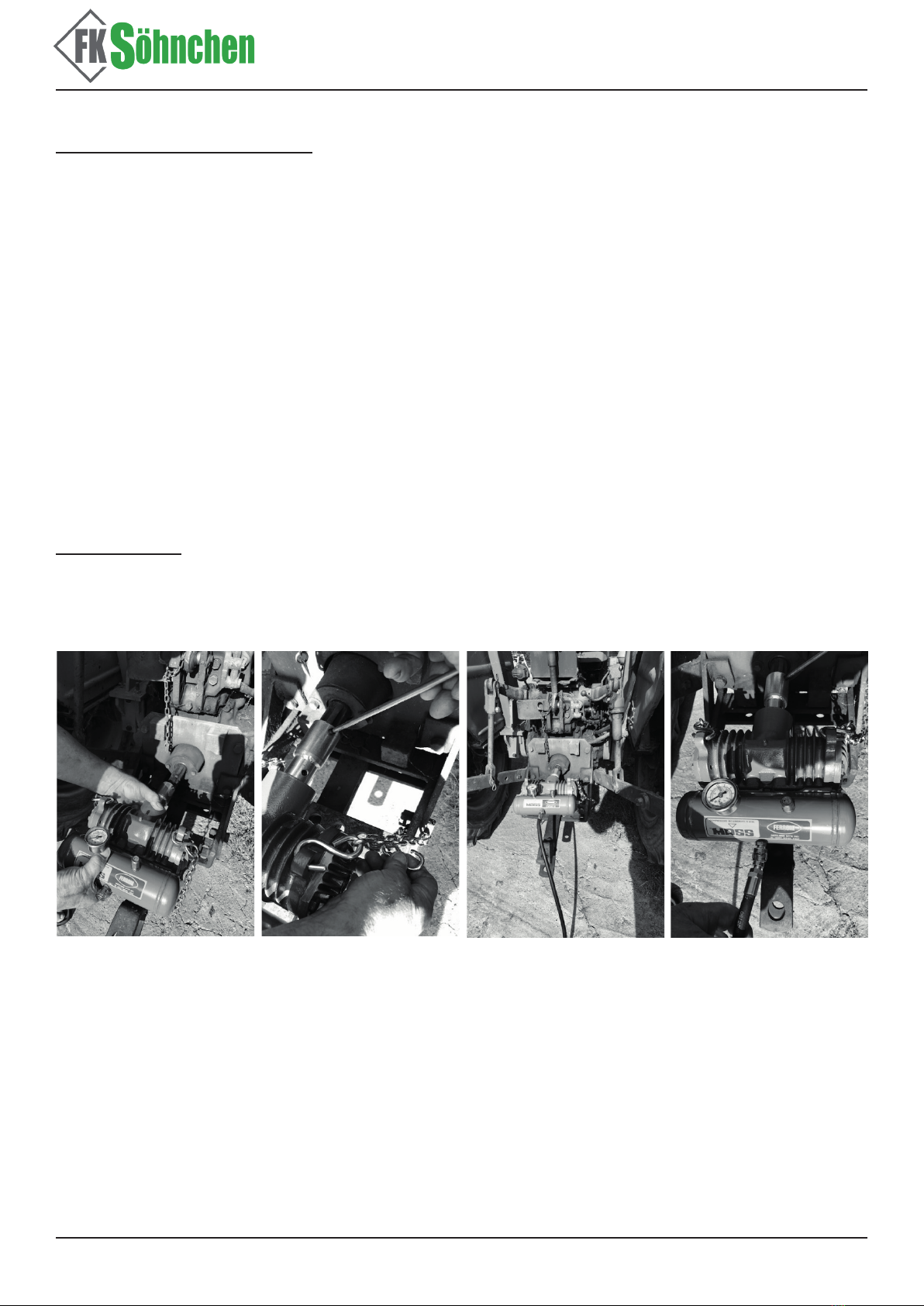
ACHTUNG! Den Kompressor bei abgestelltem Motor montieren (siehe Foto Nr. 2).
Foto Nr. 2 Foto Nr. 3 Foto Nr. 4 Foto Nr. 5
Wenn der Kompressor blockiert ist, DIE ZAPFWELLENLEISTUNG ZUR ENTSPERRUNG NICHT
BENUTZEN. Wartungsschritte ausführen, weil der Kompressor anschließend wieder betriebsbe-
reit sein könnte und dies die Gefahr vermeidet, daß die Zurkette bricht.
Die Installationsschritte des Kompressors werden auf den Fotos 2 und 3 gezeigt.
Es ist wichtig, die Schritte wie hier aufdgeführt auszuführen, damit sich die Sicherheitsketten dem
Vorschubmoment wirksam und in Sicherheit standhalten:
• Die Kompressorwelle an die Zapfwelle (PTO) des Traktors koppeln.
• Den Kompressor zur Verbindung der Traktor-Zapfwelle mit der inneren Seite der Gewindehülse
drücken. Den Kompressor bis zur Berührung der Traktor-Zapfwelle aufschieben.
• Die Gewindestifte auf den Vorschubwelle schrauben, um sie an die Traktor-Zapfwelle zu
befestigen.

Gebrauchsanweisung
Zapfwellenkompressor
• Der Kompressor soll mit den gelieferten Sicherheitsketten befestigt werden; die Ketten mit dem
S-Haken an den Kompressor verhaken und die Enden an stabilen Punkten des Traktors fest-
machen (Foto Nr. 3).
• Um die Installation zu vervollständigen, den Luftansaugschlauch in die Bajonettfassung einste-
cken (Foto Nr. 4).
Gebrauchsanweisung:
Für den korrekten Gebrauch des Kompressors muss folgendermaßen vorgegangen werden:
• Die korrekte Installation überprüfen (Foto Nr. 5).
• Sicherstellen, daß der Auslassschlauch richtig installiert worden ist.
• Langsames Anlaufen der Welle, um Stöße und Schläge auf dem gesamten Einbau zu vermei-
den.
• Für kurze Zeit bei niedriger Geschwindigkeit einlaufen lassen.
• Während der Tankladung, den auf dem Manometer gezeigten Druck kontrollieren. Warten, bis
8 bar erreicht sind, bis das Sicherungsventil ablässt.
• Wenn die gesamte Leistungsfähigkeit der Anlage geprüft wurde, kann man Luft aus dem Tank
entnehmen.
WARNUNG! Falls der Einbau nicht ausreichend stabil ist, bitte unterbrechen. Versuchen, bei
abgestelltem Motor die Kette mehr zu spannen. Falls das Sicherheitsventil nicht abläßt, dieses er-
setzen. Es können gefährliche Drücke erreicht werden.
Während der Benutzung des Kompressors sind folgende Vorgänge zu vermeiden und es ist
folgendes zu beachten:
• Während der Benutzung sind Personen und Tiere vom Traktor fernzuhalten. KEINE GEGEN-
STÄNDE bzw. KLEIDUNGEN IN NÄHE DER GETRIEBEWELLE
• Plötzliche Beschleunigungen oder Verlangsamungen der Vorschubwelle vermeiden
• Sicherstellen, dass das Zuleitungsrohr während des Betriebs nicht eingedrückt wird
• Vermeiden, daß der Kompressor ohne Schmierung betrieben wird
Nach Verwendung, den Kompressor demontieren und folgende Schritte ausführen:
• Den Traktor ausschalten und das Zuleitungsrohr vom Kompressor entfernen
• Warten, bis sich der Kompressor abkühlt.
• Die Sicherheitsketten vom Traktor lösen, die Gewindestifte der Zapfwelle lockern und den
Kompressor von der Traktor Zapfwelle abziehen.
ACHTUNG! Im Fall, dass Sie 10 Stunden Betrieb erreicht bzw. überschritten haben, schmieren
Sie (durch die zwei Öler) vor der Still-Legung des Kompressors. Vermeiden Sie Stöße an Kom-
pressor und Tank.
Wartung:
Ordentliche und vorbeugende Wartung
• Den Kompressor, besonders die Absauglter auf den Köpfen, reinigen
• Die Befestigung der Kompressor Schrauben kontrollieren
• Kontrollieren Sie das Einsetzen des Gewindestiftes der Hülse an der Kompressionwelle des
Kompressors
• Im Absatz Gebrauchsanweisung aufgelisteten Punkte sind als ordentliche Wartung anzusehen.
• Alle 10 Arbeitsstunden ist der Kompressor mit Fett zu schmieren, das üblicherweise für land-
wirtschaftliche Maschinen benutzt wird.

Gebrauchsanweisung
Zapfwellenkompressor
Importeur & Hersteller:
FK Söhnchen GmbH & Co. KG
Im Dahl 1 - 58579 Schalksmühle
Außerordentliche Wartung
Die betreenden Kompressoren sind Maschinen, die normalerweise nur bei fehlerhaftem
Gebrauch eine außerordentliche Wartung erfordern oder, wenn die Wartung unter „Ordentliche
und vorbeugende Wartung“ nicht durchgeführt wird. Wenn der Kompressor blockierte Kolben
aufweist, bitte keine Zapfwelle benutzen, um den Betrieb wiederherzustellen. In einem solchen
Fall oder im Fall vom Austauschen von Gesamtteilen, für die der Kompressor demontiert wer-
den soll, lassen Sie erfahrenes Personal eingreifen. Es wird empfohlen, sich an den nächsten
Kundendienst zu wenden oder sich mit dem Hersteller in Verbindung zu setzen.
Fehlerbehebung:
Fehler Ursachen Lösungen
Der
Kompressor
saugt nicht
Absaugkopf-Lamelle verklemmt Kopamelle bzw. gesamten Kopf ersetzen
Filter verstopft Filter reinigen
Kopamelle schließt sich nicht Kopamelle bzw. gesamten Kopf ersetzen
Abgenutzte Kolbensegmente bzw.
Kompressorkörper Segmente bzw. Kompressorkörper ersetzen.
Die Förder-
leistung ist
ungenügend
oder nicht-
existierend
Der Kompressor saugt nicht Siehe Fehler „Der Kompressor saugt nicht“
Niedrige Drehgeschwindigkeit Drehzahl der Welle erhöhen
Abgenutzter Kompressor bzw. ge-
quetschte Druckleitung Kompressor bzw. Leitung ersetzen
Undichte Verbindungen, Köpfe,
usw. Die defekten Teile ersetzen
Verlangter Druck höher als 8 bar Die Anwendung ist nicht geeignet
Der Druck
ist
ungenügend
Siehe Fehler „Die Förderleistung
ist ungenügend oder nicht-exis-
tierend
Siehe entsprechende Lösungen
Der Kompressor ist für die Anwen-
dung nicht geeignet Kompressortyp ersetzten.
Die Kompressoren, die nicht mehr verwendbar sind, müssen demontiert werden, um die Metalltei-
le von den Kunststo- oder Gummiteilen zu trennen; die Teile nicht in der Umgebung verstreuen.
Transporthinweise:
Bitte transportieren Sie die Komponenten vorsichtig.

Manual
Compressor
Item No.: 704500
Please read these instructions carefully!
Introduction:
Please read these instructions carefully, note the safe operational requirements, warnings and
cautions, use this product correctly and with care for the purpose for which it is intended.
The operations should be carried out by duly trained personnel. In case of doubts contact the ma-
nufacturer or the dealer directly.
The responsibility for installation, regardless of the kind of dragging or use allowed, is of those
who carry out the necessary operations or have them carried out before use.Failure to do so may
cause damage and/or personal unjury and will invalidate the warranty.
This handbook is composed according to Directive 89/392 EEC, therefore the installation itself
should be carried out according to this directive, with special reference to the operating conditions
and the place where the installer and the user operate.
Please keep instructions safe for future use.
Compressor

Manual
Compressor
WARRANTY
According to the warranty terms valid for representation in the respective nation or area of compe-
tence.
SAFETY STANDARDS
IMPORTANT! For the operator’s safety, please check:
1. The eciency state of the xing chains. Should these show evident signs of wear, replace
them.
2. Once the compressor is installed, make sure that the grub screws of the PTO sleeve are pro-
perly fastened and the security chains are anchored and tight to solid points on tractor.
3. Make sure that the installation and maintenance operations are carried out only when the drag-
ging shaft is still.
4. For a prolonged use, the compressor reaches high-risk temperatures. Provide therefore proper
protections.
5. Before using the compressor, check the eciency of the safety valve.
6. At least once every year test the manometer accuracy using a standard instrument. Should the
latter show an error of 2 bars, replace the manometer.
IMPORTANT NOTE
for a correct use of the compressor, the following warnings are needed:
• Clean the suction lters located on the compressor heads.
• Do not place protection devices too close to the suction inlets during operation.
• Do not use the compressor in dusty places or with humidity high level.
OPERATING CONDITIONS
Since the manufacturer knows neither the location nor the nal application, he assigns to the
installer the task of carrying out the measurements and writing them down in the table “Technical
Features”.
Harmful emissions.: In some applications, the compressor is installed near exhaust pipes (see
tractors). In such a situation, carry out installation and maintenance operations with engine o.
Identication:
Identication Plate
CHECKS AND STORAGE
The compressor is delivered in the relevant protection package. Visually check that the transport
has not caused any damage and that the contents correspond to your order. Identify the product
by the plate. In case of non-compliant results, inform the manufacturer.

Manual
Compressor
Handle and store with care. Keep in a suitable location protected from weather. Do not disperse
the protection and packaging material in the environment.
Description:
he MASS compressor is of volumetric kind with opposed pistons completely supplied with safety
valve and manometer on the tank. This kind of compressor is to be used with the aid of appropria-
te tools for tyre ination operations as well as for cleaning operations, painting etc. The compres-
sor is manufactured to work applied and operated through the tractor power-take-o (PTO) or, by
means of an adapter, the PTO of motocultivators. However, it is possible to operate it with electri-
cal, explosion or hydraulic engines or applied to connector blocks etc…provided that the operation
limits as per point no. 2.5. are not exceeded.
Dimensions
Technical Features
Max Speed 600 rpm
Min Speed 200 rpm
Max Pressure 10 bar
Engine Displacement 243 cm bar
Minimum air suction 48 dm 3/l
Max air suction 145 dm 3/l
Max absorbed power 1,1 Kw
Weight 14 Kg
Tank 1,2 dm3
Safety valve 8 bar
Max endurance time 30 min
Noise **
IMPORTANT! For other operating conditions and uses dierent to those indicated in the present
handbook, please contact the manufacturer’s technicians. Should the applicability be allowed,
proceed with the installation upon receipt of a written answer by the manufacturer, change and
integrate the handbook with the data that will be supplied.
Manual
Compressor
Assembly and rst use:
The compressor is delivered in a packaging containing:
• manometer
• wo anchor safety chains
• hose 4m length
• tyre inator valve connector
• pipe ttings
The compressor is factory tested. During the rst use, operate as follows:
1. install the device as per chapter „Installation“
2. proceed with the use as per chapter „Operating instructions“ by carrying out a running-in phase
of aprox 30 min.
3. while running-in, carry out the checks as per chapter „Operating instructions“
Make sure the compressor shaft rotates freely, during the rst use, the compressor could not freely
rotate as it needs a short running-in period.
Installation:
Make sure the compressor shaft rotates freely.
The compressor dragging shaft is hollow, allowing it to receive the power take-o shaft on which
the compressor must be placed. There is only one possible mounting direction.
WARNING! Insert the compressor with the engine o (picture no. 2)
picture no. 2 picture no. 3 picture no. 4 picture no. 5
If the compressor is blocked, DO NOT USE THE PTO POWER TO UNLOCK IT. Carry out mainte-
nance operations, since the compressor might be reusable and you avoid the risk of breaking the
hooking chain.
See pictures no. 2 and 3 for compressor installing operations. It is important to carry them out fol-
lowing what is explained hereafter until the safety chains oppose eectively and safely the drag-
ging coupler:
• Connect the compressor shaft with the tractor power take-o (PTO)
• Drive the compressor until its inside threaded sleeve touches the tractor PTO.
• Screw the grub screw on the dragging shaft to block it on the tractor PTO. Operate with a
ca.2.5/3daNm torque.

Manual
Compressor
• The compressor must be secured by using the supplied safety chain; fasten the chain through
the S shaped hook and anchor its ends to xed points of the tractor (picture no. 3).
• Complete the installation by introducing the suction air hose inside the bayonet connector (pic-
ture no. 4).
Operating Instructions:
For the compressor correct use, operating in the following way:
• Check the correct installation (see picture no. 5)
• Make sure the delivery pipe is properly connected
• Slowly rotate the shaft, avoiding snatches or shocks on the entire application.
• Conduct a short running-in at low speed
• During the tank charging period, monitor the pression indicated on the manometer. Wait until it
reaches the value of 8 bars, when the safety valve should release.
• Once checked the whole system eciency, you can withdraw air from the tank.
WARRANTY! in case the installation is not suciently stable do not proceed, but try to stretch the
chains much more, obviously with engine o. In case the safety valve does not release, proceed to
the replacement. Do not insist, the pressure reached here could be extremely high and dangerous.
While using the compressor, avoid the following manoeuvres and comply with the following directi-
ons:
• In the starting phase, move people and animals away from the tractor. NON DO NOT LEAVE
ANY OBJECT AND CLOTHING CLOSE TO THE ROTATING SHAFT
• Avoid sudden accelerations and/or decelerations of the shaft
• Make sure not to crush the delivery pipe during operation
• Avoid operating on the compressor without lubricating
After using the compressor, demount it and operate as follows:
• Switch o the tractor and remove the delivery pipe from the compressor
• Wait the compressor to cool until it reaches not dangerous temperatures (aprox. 34/40 C°
max.)
• Unhook the tractor safety chain, release the socket cup of the PTO shaft and remove the com-
pressor from the tractor PTO. Take o the pipes from the mouths, unhook the chain and remo-
ve the pump from the power take-o.
WARNING! In case you have reached or exceeded 10 hours of work, grease (through the two
lubricators) before putting the compressor to rest. Handle with care to avoid shocks on the com-
pressor compression shaft as well as on the tank.
Maintenance:
Routine and preventive maintenance
• Clean the compressor especially the aspiration lters placed on the heads
• Check the correct tightening of the compressor screws
• Check the fastening of the socket cup on the threaded sleeve to the compressor compressing
shaft
• The operations as perchapter „Operation Instructions“ are to be considered of ordinary mainte-
nance
• Every 10 hours of work, lubricate the compressor with the same grease normally used for agri-
cultural machinery

Manual
Compressor
Importer & Manufacturer:
FK Söhnchen GmbH & Co. KG
Im Dahl 1 - 58579 Schalksmühle
Extraordinary Maintenance
The compressors in question are machines that normally require extraordinary maintenance only
in case of incorrect use and if the maintenance of point „Routine and preventive maintenance“ is
not carried out.
In case the compressor pistons are blocked, do not use the power-take-o to reset function. In
such case or for other replacements of internal parts for which it is necessary to disassemble the
compressor, let skilled personnel intervene. It is advisable to apply to the nearest assistance cen-
tre or contact the manufacturer.
Defects - Demolition:
Fehler Ursachen Lösungen
The com-
pressor
does not
have suction
Suction head blade jammed Replace head blade or whole head
Filters clogged Clean the lter
Head blade does not close Replace head blade or whole head
Piston segments or compressor
body worn out Replace segments or compressor body
Insucient
delivery or
unexistent
The compressor does not have
suction
See Defect „The compressor does not have
suction“
Low rotation speed Increase the shaft turns
Worn out compressor or delivery
pipe crushed Replace compressor or pipe
Leakage in junctions, heads, etc. Replace the inecient parts
Required pression higher than 8
bars Incorrect application
Insucient
pressure
See Defect „Insucient delivery or
unexistent“
See Remedies of „Insucient delivery or
unexistent“
The compressor is unsuitable for
this application Change compressor model
The compressors that are no longer usable should be disassembled in order to separate the metal
parts from the synthetic or rubber ones; do not disperse the elements in the environment.
Transport Data:
Handle with care regardless whether the transport refers to one single box or more boxes, loose
or stacked on a pallet. Adopt such measures to avoid damages that can endanger the functional
eciency and the users’ safety.
Table of contents
Languages:
Popular Air Compressor manuals by other brands


GÜDE
GÜDE 50068 Translation of original operating instructions

California Air Tools
California Air Tools 10020AC owner's manual

Jula
Jula 079-040 operating instructions

Clarke
Clarke Panther 10/500 Operation & maintenance instructions

EINHELL
EINHELL TC-AC 190/50/8 operating instructions

AUSTIN SCIENTIFIC
AUSTIN SCIENTIFIC M600 manual