flamco Logotherm LogoThermic G2 User guide

www.flamcogroup.com/manuals
Logotherm
ENG Installation and servicing instructions
LogoThermic G2
Thermostatically controlled heat interface units
S-Line, 35 kW (UC/MC) M-Line, 46 kW (UC/MC)

LogoThermic G2 Manual
2
Acronyms
CW Domestic water, cold
DHW Domestic hot water
DWC Domestic water circulation
DWH Domestic water heating
FL Heating flow line
RL Heating return line
UC Unmixed heating circuit
MC Mixed heating circuit
PHE Plate heat exchanger
MT Male thread
FT Female thread
prim. Primary heating circuit (heat supply)
sec. Secondary heating circuit (heat consumer)
HFM Heat flow meter
SM/FM Surface-mounted / flush-mounted
Factory setting

We reserve the right to change the designs and technical specifications of our products.
3
ENG
Table of contents
Acronyms .......................................................................................................................... 2
1. Safety instructions .................................................................................................... 5
1.1 Intended use ........................................................................................................................6
1.1.1 Use for intended purpose ................................................................................................................ 6
1.1.2 Improper use .................................................................................................................................... 7
1.2 Device designation...............................................................................................................7
1.3 Hazard notes........................................................................................................................7
1.4 What to do in the event of breakdown or leaks.....................................................................8
1.5 Spare and wear parts ...........................................................................................................8
1.6 Requirements on trained engineers......................................................................................8
1.7 Liability and copyrights........................................................................................................9
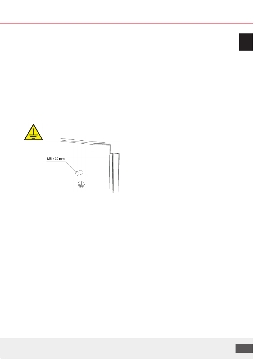
1.8 Earth bonding or protective earthing in accordance with VDE ..............................................9
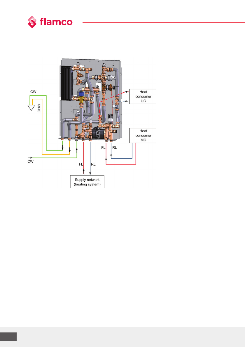
2. Functional description ............................................................................................... 9
3. LogoThermic units ................................................................................................... 10
3.1 Technical data....................................................................................................................10
3.1.1 HIU characteristics and performance parameters........................................................................ 10
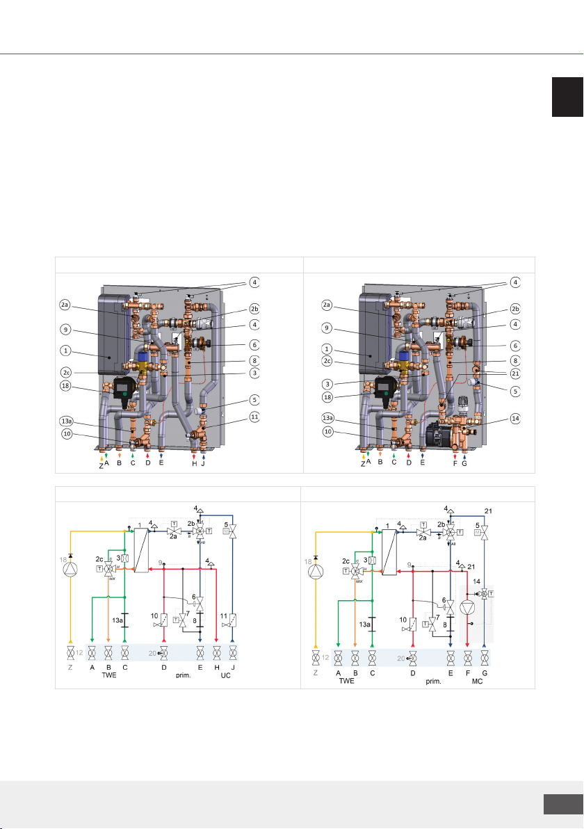
3.1.2 Components and hydraulic diagram...................................................................................11
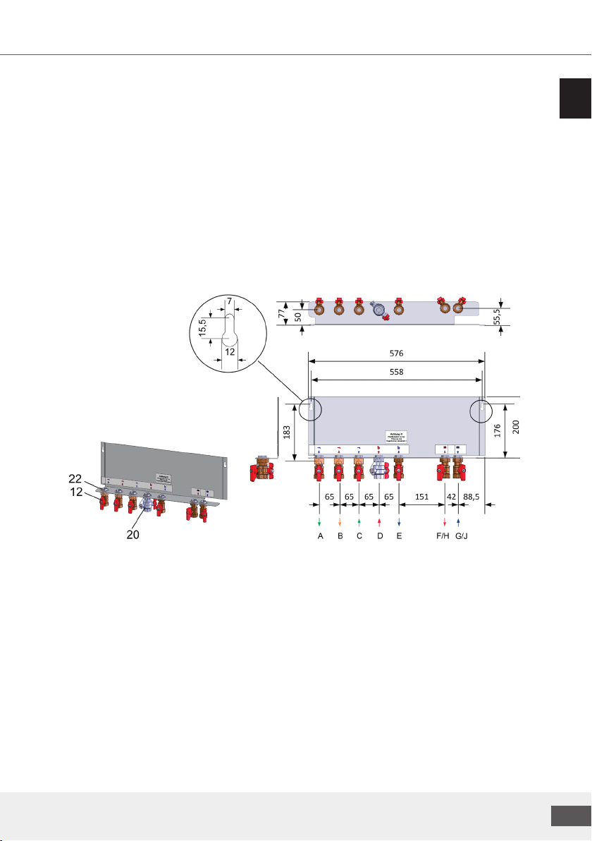
3.1.3 Dimensions ........................................................................................................................13
3.2 Variants..............................................................................................................................14
3.2.1 LogoThermic G2 with domestic hot water circulation (DWC) ...................................................... 14
3.2.2 Special variants .............................................................................................................................. 16
4. Installation ............................................................................................................. 16
4.1 SM/FM mounting rail with 7 ball valves (for MC/UC)............................................................17
4.2 DN20 ball valves, straight ...................................................................................................17
4.3 Completing stations ...........................................................................................................18
4.3.1 Optional heat meter installation ................................................................................................... 18
4.3.2 Optional water meter installation ................................................................................................. 18
5. Description of individual components and setting options .......................................... 19
5.1 Hot water limiter................................................................................................................19
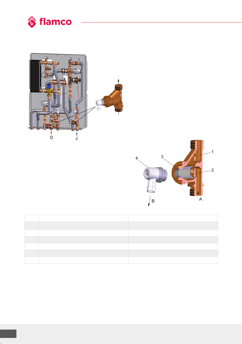
5.2 Dirt traps............................................................................................................................19
5.3 Zone valve for heating circuit .............................................................................................20
5.4 Dierential pressure regulator ...........................................................................................22
5.5 Thermostatic circulation bridge .........................................................................................23
5.6 Thermostatic control valves ...............................................................................................23
5.6.1 Thermostatic domestic water mixing valve, Flamcomix.............................................................. 24
5.6.2 Thermostatic head, type Rotherm II (only for stations with mixed heating circuit) ................... 25
5.7 Compact mixing circuit with high-eiciency pump (only for MC variant) ............................26
5.7.1 Secondary bypass on mixer (in compact mixing circuit).............................................................. 26
5.7.2 Heating circuit pump ..................................................................................................................... 26

LogoThermic G2 Manual
4
6. Optional accessories ................................................................................................ 27
6.1 Additional static heating circuit (only for MC variants) .......................................................28
6.1.1 Additional static heating circuit (for MC) and simultaneous heating circuit distribution........... 28
6.2 Heating circuit manifold for surface-mounted / flush-mounted variants ............................30
6.2.1 Standard manifold with 3 to 8 heating circuits for MC variants................................................... 30
6.2.2 Underfloor manifold with 3 to 12 heating circuits (wide version) ............................................... 31
6.2.2.1 For MC variants ..................................................................................................................................... 31
6.2.2.2 For UC variants...................................................................................................................................... 32
6.2.3 Terminal strip for underfloor heating circuit manifolds............................................................... 33
6.3 Covers and installation examples.......................................................................................35
6.3.1 Overview of surface-mounted covers (SM)................................................................................... 36
6.3.2 Overview of flush-mounted covers (FM) ....................................................................................... 36
6.3.3 FM installation examples ............................................................................................................... 37
6.3.3.1 Long version.......................................................................................................................................... 37
6.3.3.2 Standard version .................................................................................................................................. 38
6.3.3.3 Wide version.......................................................................................................................................... 39
6.4 Configuration examples .....................................................................................................40
6.4.1 Example I - LT M-Line with 12x UFH manifold via side mixer group............................................. 40
6.4.2 Example II - LT + M-Line with DWC, stat. HC and 12x UFH manifold via connection set ............. 41
6.4.3 Example III - LT+, M-Line with DWC, stat. HC and 8x UFH manifold ............................................. 42
7. Commissioning........................................................................................................ 43
7.1 Flushing and filling.............................................................................................................44
7.2 Initial start-up ....................................................................................................................44
7.3 Notes on thermostatically controlled interface stations .....................................................44
8. Maintenance and service .......................................................................................... 45
8.1 Information regarding domestic water hardness................................................................45
8.2 Maintenance checklist........................................................................................................46
9. Pressure loss diagram .............................................................................................. 47
10. Spare parts ............................................................................................................. 50
11. Decommissioning, dismantling, disposal, environmental protection and disposal of
electrical and electronic equipment .......................................................................... 52

We reserve the right to change the designs and technical specifications of our products.
5
ENG
1. Safety instructions
Please follow these safety instructions carefully to prevent hazards and injury to
persons and property.
These operating instructions are primarily designed for the safe use and installation of the device
and make no claims to completeness.
These operating instructions describe the functionality of the device and are intended to provide
information about the required safety instructions and to draw attention to possible hazards.
Further technical information can be found in the other applicable documents.
These operating instructions are valid only for the described device and are not subject to the
manufacturer’s revision service. The sketches and drawings they contain are not suitable to scale.
• Keep the operating instructions within easy reach of all employees instructed to carry out work on
the device so that they can refer to them as required.
• Keep the operating instructions in a clean, complete and legible condition throughout the entire
period of use.
• Read the operating instructions before working on the device for the first time and consult them
whenever uncertainties or doubts arise as to how the device should be handled.
• Should you come across any discrepancies when reading these operating instructions or should
anything remain unclear, please contact the manufacturer.
Target group
These instructions are intended exclusively for authorised trained experts.
Only trained experts/installers authorised by the respective competence authority are permitted to
work on heating systems and domestic water, gas and electric circuits.
Regulations
When carrying out work, you must comply with:
- The statutory accident prevention regulations,
- The statutory environmental protection regulations,
- Liability/Insurance regulations,
- The pertinent safety requirements of DIN, EN, DVGW, VDI, TRGI, TRF and VDE,
- ÖNORM, EN, ÖVGW-TR Gas, ÖVGW-TRF and ÖVE,
- SEV, SUVA, SVGW, SVTI, SWKI and VKF,
- And all new and regionally applicable regulations and standards
Instructions for working on the system
- Disconnect the system from the mains and monitor it to ensure that no voltage is being
supplied (e.g. at the separate cut-out or a main switch).
- Secure the system from restarting / switching to auxiliary power supply.
- WARNING! Risk of scalding at media temperatures: >60C

LogoThermic G2 Manual
6
Permissible mains supply and operating parameters
- Heating side/primary side: Permissible pressure rating:
Max. permissible operating temperature:
Max. permissible dierential pressure:
- With actuator for zone valve:
PN10
90°C
2.0 bar
1.0 bar
- Sanitation side: Permissible pressure rating:
Max. permissible operating temperature:
- In the case of an existing sanitary
circulation system: (for short periods
max. 70°C < 2 h)
Min. cold water pressure:
Recommended cold water operating pressure:
PN10
90°C
65°C
1 bar
2 bar
Environmental and connection conditions:
- Permissible ambient temperature: 5...40°C (non-condensing), dry ambient conditions: Avoid
installing the station in areas with high ambient humidity, as there is an increased risk of corrosion.
- The devices must be installed in enclosed, dry, frost-free spaces
- Any noise emissions or radiant heat from the station must be taken into account in the choice of
installation site
- Observe the safety areas in accordance with EN 60529 when designing and installing the system
- The fire protection classes of any thermal insulation used must be observed
- Device protection code in accordance with EN 60520 IP42
- Any sanitary installation must be made safe in compliance with DIN 1988 or DIN EN 806, i.e. with the
use of a safety valve and, where applicable, an expansion vessel.
1.1 Intended use
1.1.1 Use for intended purpose
Heat interface units are used to transfer heat between the supply network and the heat consumer.
Heat interface units may only be used for this purpose in compliance with the maintenance and operating
instructions and all relevant standards and regulations. All instructions in the operating instructions must
be followed and the maintenance plan adhered to.
Any deviation from the intended use may cause hazards and is fundamentally not permitted.
Appropriate use in heating and domestic water systems must be in accordance with the applicable DIN
and local standards. Installing and operating the assembly incorrectly will invalidate any warranty claims.
The shut-o valves may only be closed by an approved specialist when servicing, otherwise the safety
valves will not work.
Caution:
Do not make any changes to the electrical components, the design of the system or the hydraulic
components! This would adversely impact on the safe function of the system.
Instructions concerning the place of use:
Before using our products, they must be checked regarding their suitability for the respective planned
application. In particular for heating systems, please take into account the properties of the heating water
in accordance with VDI 2035 to protect the heating system and, for domestic water applications, the water
quality at the place of use.
In the case of critical water qualities, please take suitable measures where necessary (e.g. water treatment)
to prevent functional impairment and/or damage, e.g. corrosion damage.

We reserve the right to change the designs and technical specifications of our products.
7
ENG
In particular, please check the permissible limit values, e.g. electrical conductivity, the pH value,
the water hardness level and the ammonium concentration.
Furthermore, in Germany all applicable norms, regulations and guidelines specific to the federal states
must be taken into consideration, alongside the instructions in the applicable installation and operating
manuals.
Further information can be found in the download section of www.flamcogroup.com.
1.1.2 Improper use
Using the device in any way that does not correspond to the intended use may be hazardous and is
therefore prohibited.
In particular, the following is not allowed:
• The use of liquids other than water with the described properties
• Use of the device without prior knowledge of the operating instructions
• Use of the device without legible warning and information signs
• Use of the device in a faulty condition
1.2 Device designation
Designation: LogoThermic G2
Function: Transfer of thermal energy to the heating supply and hot water preparation
Type: S/M line (UC/MC)
Manufacturer: Meibes System-Technik GmbH, Gerichshain
1.3 Hazard notes
The safety and warning information draws attention to residual hazards that cannot be
avoided due to the design and construction of the device. Please always observe the
measures shown for avoiding these hazards.
Never alter or modify the unit by yourself. Such work may only be carried out by trained, specialist
personnel. This also applies to the electrical installation.
When the system is in operation, water-regulating components will be hot. Touching these system
components can lead to scalding. The interface station and its heat-carrying components must be
operated with permanent insulation. This insulation not only prevents unnecessary thermal losses,
but also protects against accidental contact and burns. The insulation must therefore only be removed
for maintenance or repair purposes and replaced correctly on completion of such work.
The system is operated using hot, high-pressure water, which can cause scalding on contact.
You should therefore open the bleed or drain valves carefully and not work on pressurised parts.
The control components (controller, servomotors, pumps, etc.) are powered by the mains voltage.
Therefore, always ensure the station is disconnected from the mains supply when carrying out any
maintenance or repair work.
Secure the system against unauthorised operation.

LogoThermic G2 Manual
8
Life-threatening electric shocks can be caused by spraying or splashing water. Escaping water may also
disable the safety devices.
Any changes made to the unit that have not been authorised by the manufacturer will invalidate any
warranty claims.
Residual hazards:
The product has been built in accordance with the most relevant and recognised safety regulations.
The following residual hazards may arise during installation, commissioning, maintenance and
disassembly:
Warning: Risk of scalding from high media temperature
• Work with particular caution.
• Use safety clothing (e.g. heat-resistant protective gloves).
• If necessary, surface temperature must be measured before commencing any work.
• Use only designated tools.
Hazard: Risk of injury from electrical voltage
• Only trained and qualified electricians may undertake work on electrical equipment.
• Electrical installation spaces must always be kept locked.
Warning: Risk of cuts and scratches due to the possibility of sharp edges
• Work with particular caution.
• Use safety clothing (e.g. protective gloves).
Warning: there is a risk of impact/crushing if the station falls over
• Wear personal protective equipment (such as protective work shoes).
1.4 What to do in the event of breakdown or leaks
• Close media lines using the appropriate valve.
• Contact a suitably trained expert or customer service of the manufacturer.
The device will only be cleared for operation again when the trained engineer has remedied
thefault and restored the device to its intended condition.
1.5 Spare and wear parts
All spare parts to be used, must correspond to the technical requirements defined by Meibes System-
Technik GmbH. This is guaranteed only by using genuine spare parts. The manufacturer is not liable for
damage caused by the use of unapproved spare parts or ancillary materials. Appropriate spare parts
can be found in our documentation.
1.6 Requirements on trained engineers
A qualified professional must have undergone advanced technical training and have suicient experience
to independently perform complicated tasks or work associated with residual hazards. Each experience
refers to a certain speciality, e.g. Maintenance, Electrical and/or HVAC Technician In preparation for
impending work, a qualified professional must be able to correctly estimate the feasibility, risks and
hazards of the work as well as the equipment required. A qualified professional is expected to understand
complex plans and descriptions of minimum preparation, and to obtain missing and required detailed
information by suitable means.
The qualified professional must be able to restore and verify the intended/original state of the system.
A worker can be a trained expert in several fields. For the performance of electrical works, only trained
electricians according to DGUV regulation 3 may be used.

We reserve the right to change the designs and technical specifications of our products.
9
ENG
1.7 Liability and copyrights
We reserve all copyrights to this document. Any misuse, in particular reproduction or disclosure to third
parties, is prohibited.
This original operating manual may not be reproduced or distributed, either in part or in its entirety,
without the express permission of the manufacturer. This also applies to translations of this document
and storage on other media. This document must not be used outside its intended purpose.
These installation and operating instructions must be given to the customer. The technician carrying
out and/or authorising the work (e.g. installer) must explain the functioning and operation of the
system to the customer in a readily comprehensible way.
1.8 Earth bonding or protective earthing in accordance with VDE
A terminal for earth bonding is provided on all interface stations. An appropriately labelled stud can be
found on the base plate for this purpose. Connection cross-section according to the applicable standards
and regulations.
Example figure:
2. Functional description
The LogoThermic G2 interface unit provides a residential unit with domestic hot water and heating.
The domestic water is heated by a stainless-steel plate heat exchanger based on the continuous flow
principle.
LogoThermic G2 - area of application
Decentralised interface transfer station for heating circuit supply and hygienic hot water preparation in
renovations and new-build properties, as the hot water preparation takes place using the continuous
flow principle.
Depending on the variant, a static heating circuit (radiators) and/or mixed heating circuit
(surface heating) can be supplied. Water heating takes priority over the heating circuit.
Features of hot water preparation with thermostatic control
Eective regulation of the hot water temperature with dierent draw-o volumes. Enhanced system
eiciency thanks to low return line temperatures (even in cases of weak hot water heating loads
due to RTL) and optimised adjustment of the primary flow.
Adjustable hot water temperature (approx. 35 to 70°C) and adjustable change-over temperature for
priority switching.
No moving parts in the domestic water zone.

LogoThermic G2 Manual
10
Further features
Adaptors for a heat and cold water meter are included in the scope of supply
with every station.
- Other accessories according to current price list
Fig. application example
3. LogoThermic units
3.1 Technical data
3.1.1 HIU characteristics and performance parameters
• Metallic base plate with fixed mounting rail
• Stainless steel plate heat exchanger and thermally insulated corrugated pipes
• Thermostatic control of water heating
• Adjustable zone valve in the heating circuit, adjustable thermal circulation bridge
• Venting option on the heating side
• One adaptor (¾" x 110 mm) for heat flow meters included
• Adaptor for water meters included
• Integrated dierential pressure regulator for hydraulic balancing
• Dirt trap in the primary inlet and secondary return flow (only for UC) to protect the station
• With MC variants, an additional UC can be connected via an optional pipe set
• Including heating circuit manifold, through ball valves ¾" and mounting rail
• Either wall-mounted or flush-mounted installation (optional accessory)

We reserve the right to change the designs and technical specifications of our products.
11
ENG
Performance parameters:
Draw-o capacity S-Line 12 l/min (35 kW); M-Line 17 l/min (46 kW)
at approx. 1 bar pressure loss,
at max. 40 K heating and 65°C FL temperature
Heating capacity - residential unit up to 10 kW (20 K)
Max. permissible temperature: 90°C
Max. permissible pressure (heating, primary side): PN 10
Max. permissible pressure (domestic water): PN 10
Note on the DHW outlet temperature: Limitation or blocking of the relevant thermostatic control elements can be used as
protection against scalding and can be changed or removed (see Section 5.6).
LogoThermic G2 - decentralised interface units, thermostatically controlled
Models:
each as an S or M-Line
with domestic water circulation
(DWC)
without drinking water circulation
(DWC)
UC:
-With thermostatic DHW
controller, circulation
bridge, plate heat
exchanger, air vent,
dierential pressure
regulator, flat sealing
connections and dirt trap
-Adaptor for water meter and
heat flow meter, adjustable
zone valve and domestic
cold water connection
MC:
-Components as for UC
-Also with thermostatically
controlled compact mixing
group with high-eiciency
heating circuit pump and
adjustable bypass for the
supply of surface heating
* Example figure

LogoThermic G2 Manual
12
3.1.2 Components and hydraulic diagram
Models:
LogoThermic G2, UC LogoThermic G2, MC
Hydraulic function diagram:
LogoThermic G2, UC LogoThermic G2, MC (with optional UC)
* Example figure

We reserve the right to change the designs and technical specifications of our products.
13
ENG
Legend:
No. Description of components
1Stainless steel plate heat exchanger (copper or stainless steel brazed; or copper brazed
with sealing)
2 a Circulation bridge (35 to 65°C) with forced leakage (for RL temperature limitation),
Factory setting: 1.5 rotations up
2 b
Thermostatic three-way valve DN 20, Kvs=3.5 in RL and startec 4-M30x1.5 thermostatic head
for setting the priority switching (20 to 50°C) 0.17 mm/K with 2 m remote sensor, factory
setting: Mark number 30, or 45 for DWC variants
2 c Flamcomix 1" DN20 (thermostatic drinking water mixing valve without RV) adjustable
35 to 70°C, factory setting: 50°C (3 rotations up)
3Flow limiter as hot water limiter with corresponding colour code:
S-Line: olive M-Line: purple
4 Venting plug ½", 10 bar, in heating SL and RL
5 Zone valve for heating circuits (option: living space controller)
6Dierential pressure regulator DN20, Kvs=2.5, adjustable: 20 to 40 kPa, factory setting: 38 kPa
7 Thermostatic circulation bridge adjustable 35 to 65°C (as keep-warm function)
8 Adaptor for optional heat meter (L = 110 mm, 2 x ¾" MT)
9 Possibility to accommodate a ½" immersion sleeve of an optional heat meter
10 VL dirt trap with flushing, filling and drain ball valve
11 RL dirt trap with flushing, filling and drain ball valve (only with UC variant)
12 Optional shut-o ball valve ¾" union nut x ¾" FT (option)
13 a Adaptor option for cold water meter L = 110 mm, 2 x ¾" MT
14
Mixing circuit with bypass and high-eiciency pump, type GF UPM3 Auto 15-70 GGMBP,
thermostatically controlled (20 to 65°C) with thermostatic valve, type Rotherm II (only with
MC variant)
18 Domestic water circulation pump, type Wilo Star-Z Nova T and separate plug-in backflow
preventer, on the domestic water side, depending on variant, see Section 3.2.1
20 Ball valve with measuring connection for optional HFM (if item 12 available)
21 Connection option for additional static heating circuit UC (only with MC version)
Note: Not all options are available or freely combinable for each station type.
Connections with dimensions (S, M-Line):
ACold water – (CW) outlet in apartment
G ¾" MT (without ball
valves)
BDomestic hot water – (DHW) domestic outlet
CCold water – (CW) inlet at building connection
DHeating – (primary FL) Supply line building connection
EHeating – (primary RL) Return line building connection
FHeating – (sec. SL) supply line to dwelling heating circuit, MC
GHeating – (sec. RL) return line from dwelling heating circuit, MC
HHeating – (sec. SL) supply line to dwelling heating circuit, UC
JHeating – (sec. RL) return line from dwelling heating circuit, UC
ZDomestic water circulation (DWC), depending on variant

LogoThermic G2 Manual
14
3.1.3 Dimensions
Dimensions of the unit with base plate and connection holes (in mm):
LogoThermic G2, UC LogoThermic G2, MC
3.2 Variants
3.2.1 LogoThermic G2 with domestic hot water circulation (DWC)
The domestic water circulation system is (DWC) used to provide a constant supply of domestic hot water
(DHW) to the taps. Long periods of disuse should be avoided! Please ensure that you comply with the
relevant technical regulations and guidelines (including for cold water CW).
LogoThermic G2, UC with DWC LogoThermic G2, MC with DWC
A backflow preventer (RV) is installed on the pressurised side of the circulation pump on the domestic
water side in order to prevent unwanted circulation.

We reserve the right to change the designs and technical specifications of our products.
15
ENG
Notes:
The water content of the longest DHW line (without taking DWC into account) should not
be
greater than
3 litres.
Any possible health risk (e.g. Legionella growth) versus possible energy savings must be borne in
mind when setting up and operating the DWC system. The relevant applicable technical rules and valid
standards must be observed and complied with.
The safety fuse of the wholesome water (sanitary) installation in a dwelling with a domestic water circulation
connection must comply with DIN 1988, i.e. with a safety valve and, if necessary, an expansion vessel.
The domestic water circulation may only be put into operation once the station has been filled with
domestic water (voltage supply 230 V). Otherwise the circulation function or connector must be taken
out of operation in order to prevent the risk of it running dry.
Notes:
The circulation pump with timer is set at the factory to run for 24 hours.
Note: the temperature control function should not be used.
Models:
LogoThermic G2, UC with DWC LogoThermic G2, MC with DWC
Hydraulic function diagram:
LogoThermic G2, UC with DWC LogoThermic G2, MC with DWC
Note: for the legend, see Section 3.1.2
The factory-set blocking of the thermostatic heads can be subsequently adjusted or removed
(see Section 5.6).
Item 2b) Three-way valve: Number 45
The temperatures must be adjusted on site as required. Please ensure that the settings comply with the standards
when using domestic water circulation.

LogoThermic G2 Manual
16
Dimensions:
LogoThermic G2, UC with DWC LogoThermic G2, MC with DWC
Example representation
Pump characteristic curve:
Areas of use of the DWC pump:
Media temperature = 2 to 95°C, ambient
temperature = 2 to 40°C, max. 10 bar,
pump protection code: IP42
The domestic water circulation pump is suitable
for use in hard water up to 20°dH.
Electrical connection:
The pump must be connected on site with
a separate 230 V power supply cable.
For the 230V/50 Hz electrical connection of the
DWC pump: see separate instructions from the
pump manufacturer!
3.2.2 Special variants
For further information and notes (e.g. connection sequence) regarding special variants, see the
separate supplementary sheets.

We reserve the right to change the designs and technical specifications of our products.
17
ENG
4. Installation
Please follow the safety instructions contained in this document and any additional assembly
instructions during installation!
Installing and operating the stations incorrectly will invalidate any warranty claims.
The LogoThermic heat interface station can be installed as follows:
A) Wall-mounted with surface-mounted cover
B) Flush or sha-mounted (set into wall) with flush-mounted cover or corresponding installation frame
Corresponding surface-mounted and flush-mounted covers are available as accessories
4.1 SM/FM mounting rail with 7 ball valves (for MC/UC)
Art. No.: M10203.181
Legend:
(12) - Shut-o ball valves straight (for DW DVGW-tested)
(20) - FL ball valve with sensor mounting option for optional HFM
(22) - Plastic plug
Notes:
Use plastic plugs only to fix the ball valves.
Please note for MC variants, there is no holding point for the optional 2nd static heating circuit and for the
DWC connection. For variants with DWC, a corresponding ball valve for the Z connection may have to be
provided separately.

LogoThermic G2 Manual
18
4.2 DN20 ball valves, straight
Legend, see Section 3.1.2
Ball valves with ¾" FT x ¾" FT union nut, with 1 ball valve with sensor
mount for HFM and domestic water ball valves, DVGW-tested
Art. No.
Version with 7 ball valves (as shown above) M10252.32
Version with 8 ball valves, for e.g. LogoThermic / LogoThermic Plus variants
with DWC and Z-connection
M10252.33
1x domestic water ball valve DVGW tested, for e.g. Z-connection M61801.22
Version with 5 ball valves, for e.g. LogoThermic Variant with lateral
connection set and underfloor manifold (for 3-12 HC)
M10252.34
4.3 Completing stations
4.3.1 Optional heat meter installation
The heat meter may only be installed once the entire heating system has been flushed through.
LogoThermic stations are fitted with an adaptor (L = 110 mm, 2x ¾" MT) for a heat meter that must be
removed before the heat meter is installed.
Procedure:
Close all shut-o valves "A” in the station.
Lower the system pressure by opening the bleeding devices
"B". Then loosen the screw fittings on the adaptor "C".
WARNING: Water may leak from the system. (The unit can
be drained via any available fill and drain valves.) Remove
the adaptor and insert the heat meter and screw it in place.
NOTE: Bear in mind the direction of flow. (Do not forget
the seals
.)
Alternatively, if ball valve with seat has been installed:
Remove the lock in position "D". Screw in and seal the heat
meter flow line sensor
Once the work is complete, re-open the shut-o valves and use the bleeding devices to bleed the unit.
Perform a leak-tightness check.

We reserve the right to change the designs and technical specifications of our products.
19
ENG
4.3.2 Optional water meter installation
LogoThermic G2 HIUs are fitted with an adaptor (with L = 110 mm, 2x ¾" MT) for a cold water
meter (B1) that must be removed before the water meter is installed.
Procedure:
All shut-o valves "A" (if present)
on the unit must be closed.
Release the screw connections on adaptor "B".
WARNING: Water may leak from the system.
Remove the adaptor and insert the water meter and screw
into place.
NOTE: Bear in mind the direction of flow. Do not forget the
seals.
Once the work is complete, re-open the shut-o valve and
check the threaded joints for leaks.
5. Description of individual components and
settingoptions
5.1 Hot water limiter
LogoThermic G2 HIUs are fitted with a hot water limiter "X".
The model with gasket simplifies the installation process (for installation position see fig.)
Observe the colour coding of the throttle plates,
e.g.:
S-Line: - Olive
M-Line: - Purple

LogoThermic G2 Manual
20
5.2 Dirt traps
Dirt traps in the units’ SL connection (and the domestic RL for UC versions) protects the system
against sludge and impurities.
Detailed structure of a dirt trap
(example illustrations):
The dirt traps can be cleaned by flushing
through the drainage device (4) or by removing
the locking screw (3) and removing the sieve
insert. Before dismantling (item 4 or 3) and
removing the sieve, depressurise the station.
Legend:
No. Components Comment
1 Meibes T dirt trap ¾“ ET / ET
2 Sieve insert for dirt trap D = 20 x 40 mm, mesh size 0.5 mm
3 Locking screw SW 24
4 Water drainage stopper 3/8"
A Direction of flow of heating water
B Drainage and flushing direction
This manual suits for next models
2
Table of contents
Other flamco Plumbing Product manuals
Popular Plumbing Product manuals by other brands

Delta
Delta 52001 Series installation instructions

AMA
AMA APHRODITE AP4500 Assembly, Use and Maintenance Manual

Health Mate
Health Mate Far Infrared Sauna owner's manual

GoldenDesigns
GoldenDesigns P6 Series instruction manual

Delta
Delta 35777LF Series installation instructions

Central Pneumatic
Central Pneumatic 90590 Assembly and operating instructions