manuals.online logo
Brands
  1. Home
  2. •
  3. Brands
  4. •
  5. flamco
  6. •
  7. Plumbing Product
  8. •
  9. flamco Prescor BFP BA User manual

flamco Prescor BFP BA User manual

Prescor BFP BA
MC01095/V1.0/08-2015
www.amcogroup.com/manuals
ENG
1. General
Application
The Prescor BFP BA back-ow preventer (EN12729) protects installations
for potable water against the back-ow of contaminated potable water up to
water class 4 (EN1717). The device consists of a non-return valve including
an integrated potable water lter, three mounted control cocks and two
(supplied loose) isolation valves.*
Nominal diameter: DN15
Nominal pressure: PN10
Temperature range: min. 1 °C / max. 65 °C
Safety
• Protect from damage, dirt and condensation during transport and
storage.
• Consult the local guidelines for potable water installations.
• Install the back-ow preventer in an easily accessible and ventilated
area (non-polluted atmosphere), which is protected from frost, extreme
temperatures and where ooding cannot occur.
• Ensure that there is sufcient capacity (size) for the drain installation.
• Use appropriate tools to prevent damage during installation and
operation.
2. Installation
The following points are important for the proper operation of the
back-ow preventer:
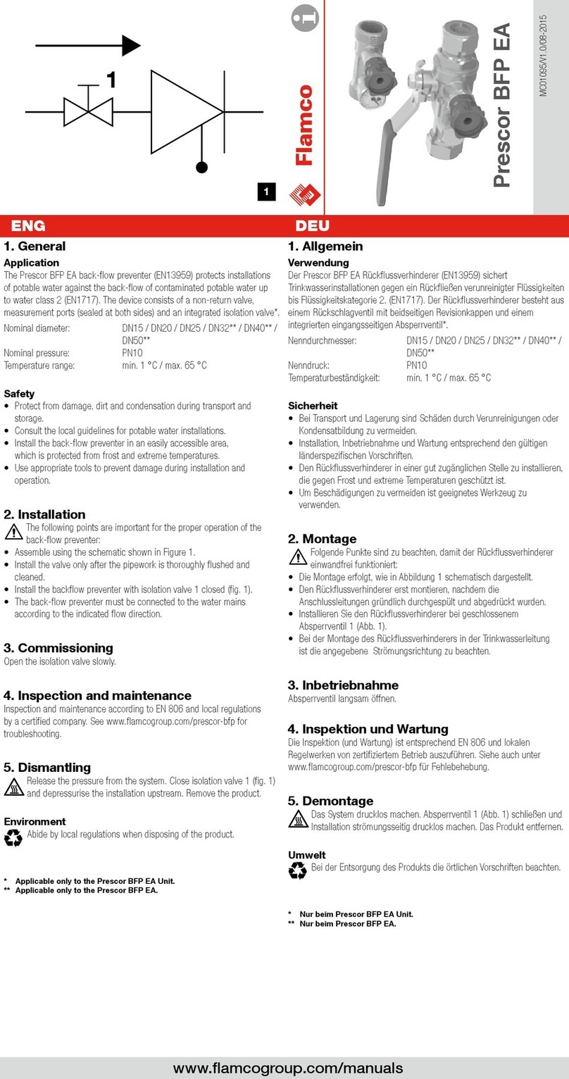
• Assemble using the schematic shown in Figure 1.
• Install the valve only after the pipework is thoroughly ushed and
cleaned.
• Install the backow preventer with closed isolation valves 1 and 2 (g. 1).
• The back-ow preventer must be connected to the water mains
according to the indicated ow direction.
• The backow preventer can be installed horizontally or vertically, with the
drain opening pointing downwards. The drain water must be piped away
so as to prevent consequential damage. In the case of vertical installation
local rules and regulations should be checked for permission.
• Afx the synthetic drain funnel (tundish) to the back-ow preventer.
Connect the tundish tension-free on to the drain. The visible openings of
the tundish must not be covered.
3. Commissioning
• Open isolation valve 2 (g. 1).
• Open isolation valve 1 slowly (g. 1).
• Bleed the backow preventer by opening and closing control cocks 3,
4 and 5 one by one until water comes out (g. 1).
4. Inspection and maintenance
Inspection and maintenance according to EN 806 and local regulations
by a certied company. See www.amcogroup.com/prescor-bfp
for troubleshooting.
5. Dismantling
Release the pressure from the system. Close isolation valve 1 and 2
(g. 1). Remove the product.
Environment
Abide by local regulations when disposing of the product.
* Applicable only to the Prescor BFP BA Unit.
DEU
1. Allgemein
Verwendung
Der Prescor BFP BA Rückussverhinderer (EN12729) sichert
Trinkwasserinstallationen gegen ein Rückießen verunreinigter Flüssigkeiten
bis Flüssigkeitskategorie 4. (EN1717). Der Rückussverhinderer besteht aus
einem Rückschlagventil mit integriertem Trinkwasserlter, drei montierten
Kontrollventilen und zwei losen Absperrventilen.*
Nenndurchmesser: DN15
Nenndruck: PN10
Temperaturbeständigkeit: min. 1 °C / max. 65 °C
Sicherheit
• Bei Transport und Lagerung sind Schäden durch Verunreinigungen oder
Kondensatbildung zu vermeiden.
• Installation, Inbetriebnahme und Wartung entsprechend den gültigen
länderspezischen Vorschriften.
• Der Rückussverhinderer ist an einer gut zugänglichen, belüfteten Stelle
(keine belastete Umgebungsatmosphäre) zu installieren, die gegen
Frost, extreme Temperaturen und Hochwasser geschützt ist.
• Für ausreichendes Fassungsvermögen des Ablaufs sorgen.
• Um Beschädigungen zu vermeiden ist geeignetes Werkzeug zu
verwenden.
2. Montage
Folgende Punkte sind zu beachten, damit der Rückussverhinderer
einwandfrei funktioniert:
• Die Montage erfolgt, wie in Abbildung 1 schematisch dargestellt.
• Den Rückussverhinderer erst montieren, nachdem die Leitungen
gründlich durchgespült und abgedrückt wurden.
• Der Rückussverhinderer ist mit geschlossenen Absperrventilen 1 und 2
(Abb. 1) zu montieren.
• Bei der Montage des Rückussverhinderers in der Trinkwasserleitung
ist die angegebene Strömungsrichtung zu beachten.
• Der Rückussverhinderer kann, mit nach unten gerichtetem Trichter,
sowohl horizontal wie auch vertikal installiert werden. Das Wasser in
der Weise ablassen, dass keine Schäden verursacht werden.
Bei vertikaler Installation sollte dies nur in Übereinstimmung mit lokalen
Regelwerken erfolgen.
• Den Kunststoff-Ablauftrichter am Rückussverhinderer befestigen.
Der Trichter soll spannungsfrei am Ablass angeschlossen werden
Inbetriebnahme. Die Belüftungsöffnungen des Ablauftrichters dürfen
nicht abgedeckt werden.
3. Inbetriebnahme
• Absperrventil 2 (Abb. 1) öffnen.
• Absperrventil 1 (Abb. 1) langsam öffnen.
• Entlüften Sie die Rückussverhinderer durch Öffnen und Schließen
Regelhähne 3, 4 und 5 einen nach dem anderen, bis Wasser austritt
(Abb. 1).
4. Inspektion und Wartung
Die Inspektion (und Wartung) ist entsprechend EN 806 und lokalen
Regelwerken von zertiziertem Betrieb auszuführen. Siehe auch unter
www.amcogroup.com/prescor-bfp für Fehlebehebung.
5. Demontage
Das System drucklos machen. Absperrventile 1 und 2 (Abb. 1)
schließen. Das Produkt entfernen.
Umwelt
Bei der Entsorgung des Produkts die örtlichen Vorschriften beachten.
* Nur beim Prescor BFP BA Unit.
STR
12
3 4 5
1
www.amcogroup.com/manuals
NLD
1. Algemeen
Toepassing
De Prescor BFP BA terugstroombeveiliger (EN12729) beschermt
drinkwaterinstallaties tegen terugstroming van verontreinigd drinkwater tot
en met waterklasse 4 (EN1717). Het toestel bestaat uit een keerklep met
geïntegreerd drinkwaterlter, drie gemonteerde controlekranen en twee
losse afsluiters.*
Nominale diameter: DN15
Nominale druk: PN10
Temperatuurbestendigheid: min. 1 °C / max. 65 °C
Veiligheid
• Voorkom schade, vuil en condensvorming b transport en opslag.
• Raadpleeg lokaal geldende richtlnen voor drinkwaterinstallaties.
• Installeer de terugstroombeveiliger in een goed toegankelke
geventileerde ruimte (geen verontreinigde atmosfeer), beschermt tegen
vorst en extreme temperaturen en waar geen overstroming kan optreden.
• Zorg voor voldoende capaciteit van de afvoerinstallatie.
• Gebruik geschikt gereedschap om beschadigingen te voorkomen.
2. Installatie
De volgende punten zijn van belang voor een correcte werking van
de terugstroombeveiliger:
• Bouw de schematisch weergegeven samenstelling in afbeelding 1.
• Installeer de terugstroombeveiliger pas nadat de leidingen grondig zijn
doorgespoeld en afgeperst.
• Installeer de terugstroombeveiliger met gesloten afsluiters 1 en 2
(zie afb. 1).
• Installeer de terugstroombeveiliger in de juiste stromingsrichting in de
drinkwaterleiding.
• De terugstroombeveiliger moet horizontaal of verticaal worden
geïnstalleerd met de afvoeropening naar beneden gericht.
Het af te voeren water mag geen schade veroorzaken. Voor verticale
plaatsing is goedkeuring van lokale inspectie nodig.
• Bevestig de kunststof afvoertrechter aan de terugstroombeveiliger.
Sluit de afvoer spanningsvr op de trechter aan.
De beluchtingsopeningen van de afvoertrechter mogen niet afgedekt
worden.
3. Inbedrfstelling
• Open afsluiter 2 (zie afb. 1).
• Open afsluiter 1 langzaam (zie afb. 1).
• Ontlucht de beveiliger door controlekranen 3, 4 en 5 na elkaar
te openen en te sluiten zodra er water uitkomt (zie afb. 1).
4. Inspectie en controle
Inspectie en controle volgens EN 806 en lokaal geldende richtlnen door
een gecerticeerd bedrf. Kk op www.amcogroup.com/prescor-bfp
voor de probleemoplosser.
5. Demontage
Maak het systeem drukloos. Sluit de afsluiters 1 en 2 (zie afb. 1).
Verwder het product.
Milieu
Houdt u zich aan de lokale wetgeving wanneer het product wordt
afgevoerd.
* Alleen van toepassing op de Prescor BFP BA Unit.
FRA
1. Généralités
Application
Le disconnecteur Prescor BFP BA (EN12729) protège les installations
d’eau potable contre le reux d’eau potable contaminée jusqu’à et y
compris la classe d’eau 4 (EN1717). L’appareil se compose d’un clapet
anti-retour avec ltre d’eau potable intégré, de trois vannes de commande
et de deux vannes d’isolement distinctes.*
Diamètre nominal : DN15
Pression nominale : PN10
Résistance à la température : min. 1 °C / max. 65 °C
Sécurité
• Évite les dommages, l’encrassement et la formation de condensation
lors du transport et de l’entreposage.
• Consulter les directives locales en vigueur pour les installations
d’eau potable.
• Monter le disconnecteur dans un local aisément accessible et
correctement ventilé (pas d’atmosphère contaminée), à l’abri du gel,
de températures extrêmes et d’inondations.
• Veiller à ce que l’installation d’évacuation présente une capacité
sufsante.
• Utiliser des outils appropriés an d’éviter tout endommagement.
2. Montage
Les points suivants sont importants pour un fonctionnement correct
du disconnecteur:
• Assembler le dispositif indiqué schématiquement dans la gure 1.
• Monter le disconnecteur uniquement après avoir procédé à un rinçage
et à un contrôle d’étanchéité minutieux des conduites.
• Installer le disconnecteur avec les vannes d’isolement 1 et 2 en position
fermée (g. 1).
• Le disconnecteur doit être raccordé à la conduite d’eau potable
conformément à la direction de ux indiquée.
• Le disconnecteur peut être installé horizontalement ou verticalement
avec l’entonnoir orienté vers le bas. L’eau évacuée ne doit pas causer de
dommages. Un accord de l’organisme d’inspection local est nécessaire
en cas d’installation verticale.
• Fixer l’entonnoir d’évacuation en plastique sur le disconnecteur.
Raccorder de manière souple (non rigide) l’entonnoir du disconnecteur
à la conduite d’évacuation. Il est interdit d’obturer les orices d’aération
de l’entonnoir d’évacuation.
3. Mise en service
• Ouvrir la vanne d’isolement 2 (g. 1).
• Ouvrir lentement la vanne d’isolement 1 (g. 1).
• Purger le disconnecteur en ouvrant et en fermant une à une les vannes
de contrôle 3, 4 et 5 jusqu’à ce que de l’eau s’écoule (g. 1).
4. Inspection et entretien
L’inspection (et l’entretien) doivent être effectués par une société agréée,
en conformité avec la norme EN 806 et les réglementations locales en
vigueur. Consulter www.amcogroup.com/prescor-bfp pour la résolution
des problèmes.
5. Démontage
Dépressuriser l’installation. Fermer les vannes d’isolement 1 et 2
(g. 1). Déposer le produit.
Environnement
Respecter la législation locale lors de la mise au rebut du produit.
* Uniquement d’application pour le disconnecteur Prescor BFP BA Unit.
STR
12
3 4 5
1

Other flamco Plumbing Product manuals

flamco Flexofit S User manual

flamco

flamco Flexofit S User manual

flamco Prescor IC 1/2 User manual

flamco

flamco Prescor IC 1/2 User manual

flamco Logotherm LogoThermic G2 User guide

flamco

flamco Logotherm LogoThermic G2 User guide

flamco Flamcovent Clean User manual

flamco

flamco Flamcovent Clean User manual

flamco Prescor BFP EA User manual

flamco

flamco Prescor BFP EA User manual

Popular Plumbing Product manuals by other brands

Moen SANI-STREAM 8797 manual

Moen

Moen SANI-STREAM 8797 manual

Grohe Allure Brilliant 19 784 manual

Grohe

Grohe Allure Brilliant 19 784 manual

Cistermiser Easyflush EVO 1.5 manual

Cistermiser

Cistermiser Easyflush EVO 1.5 manual

Kohler Triton Rite-Temp K-T6910-2A installation guide

Kohler

Kohler Triton Rite-Temp K-T6910-2A installation guide

BEMIS FNOTAB100 Installation instruction

BEMIS

BEMIS FNOTAB100 Installation instruction

Hans Grohe ShowerTablet Select 700 13184000 Instructions for use/assembly instructions

Hans Grohe

Hans Grohe ShowerTablet Select 700 13184000 Instructions for use/assembly instructions

Akw Stone Wash Basin Installation instructions manual

Akw

Akw Stone Wash Basin Installation instructions manual

Enlighten Sauna Rustic-4 user manual

Enlighten Sauna

Enlighten Sauna Rustic-4 user manual

Moen ShowHouse S244 Series quick start guide

Moen

Moen ShowHouse S244 Series quick start guide

Sanela SLWN 08 Mounting instructions

Sanela

Sanela SLWN 08 Mounting instructions

Franke 7612982239618 operating instructions

Franke

Franke 7612982239618 operating instructions

Heritage Bathrooms Granley Deco PGDW02 Fitting Instructions & Contents List

Heritage Bathrooms

Heritage Bathrooms Granley Deco PGDW02 Fitting Instructions & Contents List

Tres TOUCH-TRES 1.61.445 instructions

Tres

Tres TOUCH-TRES 1.61.445 instructions

STIEBEL ELTRON WS-1 Operation and installation

STIEBEL ELTRON

STIEBEL ELTRON WS-1 Operation and installation

Miomare HG00383A manual

Miomare

Miomare HG00383A manual

BELLOSTA revivre 6521/CR1 quick start guide

BELLOSTA

BELLOSTA revivre 6521/CR1 quick start guide

American Standard Heritage Amarilis 7298.229 parts list

American Standard

American Standard Heritage Amarilis 7298.229 parts list

BorMann Elite BTW5024 quick start guide

BorMann

BorMann Elite BTW5024 quick start guide

manuals.online logo
manuals.online logoBrands
  • About & Mission
  • Contact us
  • Privacy Policy
  • Terms and Conditions

Copyright 2025 Manuals.Online. All Rights Reserved.