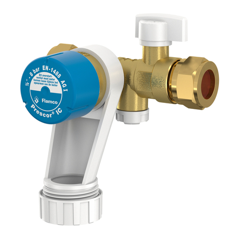
flamco Flexofit S User manual

1. Algemeen
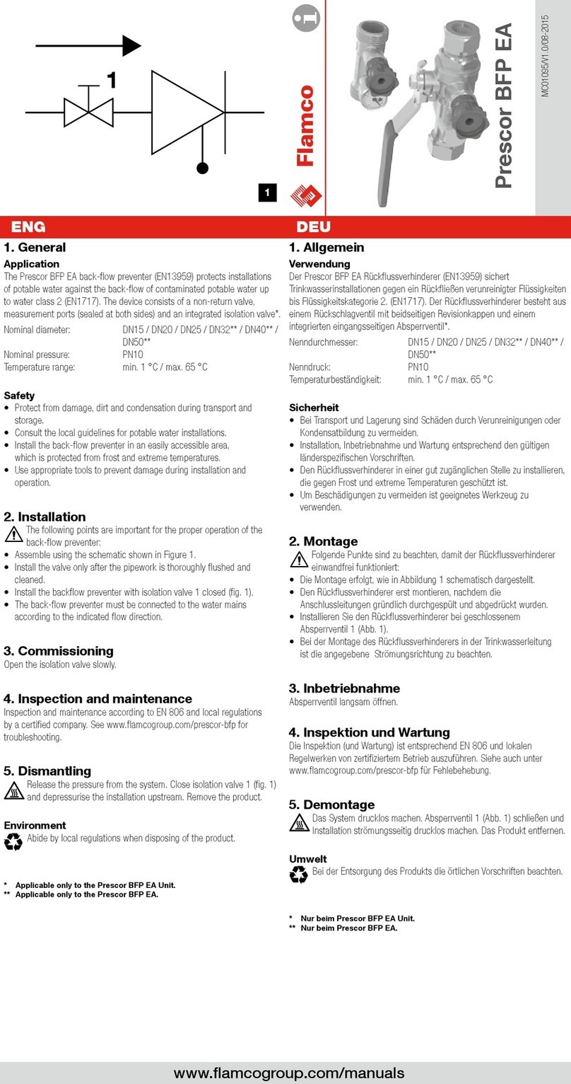
Deze handleiding is geldig voor Flexofit waterslagdempers.
Toepassing
• waterslagdempers zijn bedoeld voor gebruik in koudwaterleidingen van
sanitaire installaties (KIWA-richtlijn: Tmax. 30 °C).
• Min./max. toelaatbare temperatuur op het membraan is +4 °C / 90 °C.
• Max. werkdruk: 10 bar (piek belasting 40 bar).
• Max. schokdruk: 15 bar.
Veiligheid
De wordt met voordruk geleverd: beschadiging kan ernstige schade en
verwonding veroorzaken.
2. Installatie
De volgende punten zijn van belang om de goede werking van de
waterslagdemper te verzekeren.
• Houdt u zich aan de lokale regelgeving en richtlijnen.
• Installeer bij een waterdruk boven 6 bar een drukreduceerventiel na de watermeter.
• Zorg voor een geringe watersnelheid in het systeem door een juiste leidingdiameter
te kiezen.
• Voer de installatie uit op een drukloos systeem.
• Monteer de waterslagdemper zo dicht mogelijk bij de veroorzaker van
waterslag
• Monteer de waterslagdemper in een ½
binnendraad (A), bijvoorbeeld in een
T-stuk 2).
• Gebruik afdichttape (B) (gebruik geen hennep!) op de aansluiting van de
waterslagdemper 2).
• Gebruik voor montage de daarvoor bestemde sleutelvlakken (C) 2).
• Voor montage tussen was- en afwasmachinekraan en slang kan gebruik gemaakt
worden van het speciale T-stuk (D), artikelnummer: 24985 3).
Let op!
Onder de zwarte dop zit het gasventiel (E). Dit nooit indrukken. Hierdoor verliest
de demper zijn dempend vermogen 4).
3. Demonteren
1. Maak het systeem drukloos.
2. Verwijder de waterslagdemper.
Milieu
Houdt u zich aan de lokale regelgeving bij het afvoeren van de
waterslagdemper.
Selectietabel
Onderstaande tabel geeft aan tot welke werkdruk een gebruikt kan worden bij
een bepaalde pijp met een bepaalde lengte. Bij hogere drukken moet u twee
monteren. De aangegeven waarden zijn gebaseerd op een watersnelheid van 3 m/s en
een maximale schokdruk van 10 bar.
Zie ook www.flamcogroup.com / Weitere Informationen unter www.flamcogroup.com
Selectietabel / Auswahltabelle
Systeemdruk in bar / Betriebsdruck der Anlage in bar 2,0 2,5 3,0 4,0 4,5 5,0 6,0 6,5 7,0
Pijpmaat Max. pijplengte Aantal te monteren Flexofits
tot ... meter
Durchmesser der Max. Rohrleitungslänge Anzahl der einzubauenden Flexofit
Rohrleitung bis ... Meter
½ (15 mm) 15 1 1 1 1 1 1 2 2 2
20 1 1 1 1 2 2 2 - -
30 1 1 2 2 2 2 - - -
¾ (22 mm) 7,5 1 1 1 1 1 1 2 2 2
15 1 1 2 2 2 2 - - -
20 2 2 2 2 - - - - -
1 (28 mm) 7,5 1 1 1 1 2 2 2 - -
15 2 2 2 2 - - - - -
20 2 - - - - - - - -
1¼ (35 mm) 7,5 2 2 2 2 2 - - - -
1. Allgemeines
Diese Anleitung gilt für Wasserschlagdämpfer.
Einsatzbereich
Wasserschlagdämpfer sind für den Einsatz in sanitären Anlagen vorgesehen.
• Die niedrigst- bzw. höchstzulässige Temperatur an der Membran beträgt
+4 °C bzw. 90 °C.
• Maximaler Betriebsdruck: 10 bar (Spitzenlast 40 bar).
• Maximal zulässige Schließdruckspitze: 15 bar.
Sicherheit
Der ist mit Druck beaufschlagt: Eine Beschädigung des kann zu
ernsthaften System- oder Umweltschäden oder Verletzungen von Personen führen.
2. Einbau
Durch die genaue Beachtung der nachstehenden Anweisungen ist sichergestellt,
dass der Wasserschlagdämpfer ordnungsgemäß funktioniert.
• Beachten Sie die örtlichen Vorschriften und Richtlinien.
• Für die einwandfreie Funktion des ist nach dem Wasserzähler ein
Druckminderer vorzusehen.
• Begrenzen Sie die Fließgeschwindigkeit in der Anlage durch die Wahl des richtigen
Rohrleitungsdurchmessers.
• Die Anlage ist vor dem Einbau des Wasserschlagdämpfers drucklos zu machen.
• Installieren Sie den Wasserschlagdämpfer so nah wie möglich an der den
Wasserdruckstoß erzeugenden Verursacher (Abb. 1).
• Zur Montage des Wasserschlagdämpfers wird ein ½
-Innengewinde, z.B.
in ein T-Stück (A) (Abb. 2) benötigt.
• Verwenden Sie PTFE-Band (keinen Hanf!) zum Abdichten des Wasserschlag-
dämpfers (B) (Abb. 2).
• Verwenden Sie für die Montage einen passenden Schraubenschlüssel (C) (Abb. 2).
• Ein spezielles T-Stück (Artikelnummer 24985) ermöglicht die Montage des
Wasserschlagdämpfers direkt zwischen Zapfstelle und dem Schlauch z.B. einer
Wasch- oder Spülmaschine (D) (Abb. 3).
Hinweis:
Das Gasventil (E) sich unter der schwarzen Abdeckkappe.
Drücken Sie nicht auf Stift im Gasventil, dadurch verliert der Wasserschlag-
dämpfer seine Dämpffähigkeit (Abb. 4).
3. Ausbau
1. Machen Sie das System drucklos.
2. Bauen Sie den Wasserschlagdämpfer aus.
Umweltschutz
Beachten Sie bei der Entsorgung des Wasserschlagdämpfers die
entsprechenden örtlichen Vorschriften und Bestimmungen.
Auswahltabelle
Die Tabelle unten zeigt den maximalen Betriebsdruck eines für verschiedene
Durchmesser und Längen der Rohrleitung. Bei höheren Drücken sind eventuell zwei
zu installieren. Die angegebenen Werte basieren auf einer Fließgeschwindigkeit
von 3 m/s und einer maximalen Schließdruckspitze von 10 bar.
NL DE
Flexofit S
½
1018505662 / 2010
B
A
C
D
E
Copyright Flamco b.v.
Bunschoten,
The Netherlands
Flamco
1
2
3
4

1. Généralités
Ce manuel présente les amortisseurs de coups de bélier
Application
• Les amortisseurs de coups de bélier sont conçus les installations sanitaires.
• La température minimum / maximum autorisée sur la membrane est +4 °C / 90 °C.
• Pression de service maximum: 10 bar (charge de pointe: 40 bar).
• Pression de pointe maximum: 15 bar.
Sécurité
Le est pressurisé: un endommagement du peut entraîner de
sérieux dommages à l’installation/à l’environnement ou des blessures.
2. Installation
Le respect des points ci-dessous garantit un fonctionnement correct de
l’amortisseur de coups de bélier
• Respecter la législation et les directives locales.
• Si la pression de l’eau dépasse 6 bar, monter un réducteur de pression en aval du
compteur d’eau.
• Veiller à ce que la vitesse de l’eau dans l’installation soit limitée en sélectionnant le
diamètre de conduite correct.
• Veiller à ce que l’installation soit dépressurisée avant de procéder au montage.
• Monter l’amortisseur de coups de bélier le plus près possible de l’appareil
générant les coups de bélier
• Monter l’amortisseur de coups de bélier dans un femelle ½
(A), par
exemple dans un raccord en T 2).
• Appliquer du ruban PTFE (B) (ne pas utiliser de chanvre!) sur le de
l’amortisseur de coups de bélier 2).
• Pour le montage, utiliser les clés appropriées (C) 2).
• Un raccord en T spécial (référence: 24985) peut être utilisé pour montage entre
le robinet et le d’un lave-linge/d’une machine à laver la vaisselle (D) 3).
Note:
aL valve d’azote (E) se trouve sous le capuchon noir. Ne pas enfoncer cette
valve; cela fait perdre au sa capacité d’amortissement 4).
3. Dépose
1. Dépressuriser l’installation.
2. Déposer l’amortisseur de coups de bélier
Données environnementales
Respecter la législation et les règlements locaux en vigueur lors de la mise au
rebut de l’amortisseur de coups de bélier
Tableau de sélection
Le tableau ci-dessous indique la pression de service maximum du pour une
conduite déterminée d’une longueur déterminée. Pour des pressions supérieures, il
peut être nécessaire de monter deux Les valeurs indiquées sont basées sur
une vitesse de l’eau de 3 m/s et une pression de pointe maximum de 10 bar.
Voir aussi www.flamcogroup.com / See also www.flamcogroup.com
1. General
This manual applies to water shock arrestors.
Application
water shock arrestors are intended for use in sanitary installations.
• Minimum / maximum permissible temperature on the diaphragm is +4 °C / 90 °C.
• Maximum operating pressure: 10 bar (peak load 40 bar).
• Maximum intermittent pressure: 15 bar.
Safety
The is pressurized: damage to the may lead to serious damage to
the system/environment or personal injury.
2. Installation
Following the points below will ensure that the water shock arrestor
works properly.
• Observe local legislation and guidelines.
• If the water pressure exceeds 6 bar, a pressure reducing valve after the water
meter.
• Ensure that the water speed in the system is restricted by selecting the correct pipe
diameter.
• Ensure that the system is pressure-free before starting installation.
• Install the water shock arrestor as close as possible to the source of the
water back-pressure
• Install the water shock arrestor in a ½” female thread (A), for example in a
T-piece 2).
• Use PTFE tape (B) (do not use hemp!) on the water shock arrestor thread
2).
• For installation, use the appropriate spanners (C) 2).
• A special T-piece (article number: 24985) can be used for installation
between a washing machine/dishwasher tap and hose (D) 3).
Note:
The gas valve (E) is under the black cap. Do not press the black cap.
This will cause the arrestor to lose its damping capacity 4).
3. Removal
1. De-pressurize the system.
2. Remove the water shock arrestor.
Environmental considerations
Observe local legislation and regulations when disposing of the water
shock arrestor.
Selection table
The table below shows the maximum operating pressure for a for a
pipe of a length. At higher pressures, you may have to install two
The values shown are based on a water speed of 3 m/s and a maximum intermittent
pressure of 10 bar.
Tableau de sélection / Selection table
Pression du système en bars / System pressure in bar 2,0 2,5 3,0 4,0 4,5 5,0 6,0 6,5 7,0
Diamètre de la Longueur max. de conduite Nombre de Flexofits à monter
conduite jusqu’à … mètres
Pipe diameter Max. pipe length Number of Flexofits to be installed
up to … metres
½ (15 mm) 15 1 1 1 1 1 1 2 2 2
20 1 1 1 1 2 2 2 - -
30 1 1 2 2 2 2 - - -
¾ (22 mm) 7,5 1 1 1 1 1 1 2 2 2
15 1 1 2 2 2 2 - - -
20 2 2 2 2 - - - - -
1 (28 mm) 7,5 1 1 1 1 2 2 2 - -
15 2 2 2 2 - - - - -
20 2 - - - - - - - -
1¼ (35 mm) 7,5 2 2 2 2 2 - - - -
Flexvent
®
FR GB
1
2
3
4
Flexofit S
½
1018505662 / 2010
B
A
C
D
E
Copyright Flamco b.v.
Bunschoten,
The Netherlands
Flamco
Other flamco Plumbing Product manuals
Popular Plumbing Product manuals by other brands

Lacava
Lacava ELEGANZA 1803 owner's manual
Intra
Intra IND01N Instructions for use
Viega
Viega Advantix base unit Instructions for use
Hans Grohe
Hans Grohe Aqittura M91 210 1jet sBox 76800 Series Instructions for use/assembly instructions
Hans Grohe
Hans Grohe Decor 240 2jet 31815 3 Series Instructions for use/assembly instructions
Tres
Tres Cuadro-Tres 008.151.01 instructions

ProFlo
ProFlo PFWSC4850CP installation instructions
Pfister
Pfister Solo LF029-4SL installation guide
Moen
Moen MONTICELLO T953 Series Specifications
Kalia
Kalia BF1065 UMANI Installation instructions / warranty
JETStream
JETStream UWE MIRO 1 TRANSLATION OF INSTALLATION AND OPERATING INSTRUCTIONS
Kohler
Kohler 8030A Installation and user guide
