Flare KP-017 Service manual
SWIMMING POOL HEAT PUMP UNIT
Installation & Instruction Manual

1. 1
2. Specifications 2
2.1 Performance Data of Swimming Pool Heat Pump Unit 2
2.2 Dimensions for Swimming Pool Heat Pump Unit 2
3. Installation and Connection 4
3.1 Installation of System 4
3.2 Swimming Pool Heat Pumps Location 5
3.3 How Close to Your Pool? 5
3.4 Swimming Pool Heat Pumps Plumbing 6
3.5 Swimming Pool Heat Pumps Electrical Wiring 7
3.6 Initial Start-up of the Unit 7
4. Usage and Operation 8
4.1 The Functions of the LCD Controller 8
4.2 How to Set Operation Parameter 8
4.3 To Choose Mode 9
4.4 How to know the Current Status 9
4.5 Operation Data Setting 10
5. Maintenance and Inspection 11
5.1 Maintenance 11
5.2 Trouble Shooting Guide 11
6. Appendix 12
6.1 Connection of PCB Illustration 12
Preface
CONTENTS
2.3 Discription of parts 3

1. PREFACE
●In order to provide our customers with quality, reliability and versatility,
this product has been made to strict production standards. This manual
includes all the necessary information about installation, debugging,
discharging and maintenance. Please read this manual carefully before
you open or maintain the unit. The manufacture of this product will not be hel
d responsible if someone is injured or the unit is damaged, as a result of
improper installation, debugging, or unnecessar y maintenance. It is vital
that the instructions within this manual are adhered to at all times.
The unit must be installed by qualifi ed personnel.
●The unit can only be repaired by qualified installer centre
personnel or an authorised dealer.
●Maintenance and operation must be carried out according to the
recommended time and frequency, as stated in this manual.
●Use genuine standard spare parts only.
Failure to comply with these recommendations will invalidate the warranty.
●Swimming Pool Heat Pump Unit heats the swimming pool water and
keeps the temperature constant.
This type of pump has the following characteristics:
1 Durable
The heat exchanger is made of PVC & titanium tube which can
withstand prolonged exposure to corrosives such as chlorine.
2 Installation flexibility
The unit can be installed outdoors or indoors.
3 Quiet operation
The unit comprises an effi cient rotary/ scroll compressor and a low-
noise fan motor, which guarantees its quiet operation.
4 Advanced controlling
The unit includes micro-computer controlling, allowing all operation
parameters to be set. Operation status can be displayed on the wire
controller.
1
6. APPENDIX
12
6.1 Connection of protectio n PCB illu stratio n
Y/G
C1
FAN MOTOR
C2
PCB
FM
XT1
RED
WHITE
R
S
C
COMPRESSOR
CM
CM
C1
BLACK
4
3
NL
LDB-1
C2
FM
OUT5
PCB
CONTROL BOARD
CREEPAGE
EXAMINE
LDB-1
WATER
TEMP.
COPPER
SENSOR
POWER
Y/G
COMPRESSOR
CAPACITOR 1
FAN MOTOR
CAPACITOR 2
COMPRESSOR
TEMPERATURE
/
3
CN3
LED
TRANSFORMER
AMBIENT
TEMPERATURE
BLACK
WHITE
CN1
CN2 CN4
WHITE
OUT4OUT3 OUT6 OUT7
M
HEATER
4
3
BLUE
BLUE
BLUE
BLUE
BLACK
YV1
YV2
BXT2
YV1 FOUR WAY
VALVE
YV2 SOLENOID
VALVE
XT1 TERMINAL
XT2 PUBLIC
TERMINAL
N
L
Y/G

2
2.SPECIFICATION
Check the water su pply devi ce and the release often. You sh ould avo id the condition of no water or air entering
into system , as this will influence unit's per formance and reliability. You sh ould clear the pool/sp a filter regularly
to avoid damage to the unit as a resu lt of the dirty of clogged filter.
The area ar oun d the un it shou ld be dr y, cl ean and wel l ve nt ilat ed. Cl ean the side heat ing ex chan ger
regul ar ly to mai nt ain good heat ex chan ge as con ser ve ene rgy .
The operation pressure of the refrigerant syst em sho uld only be se rvi ced by a cer tified technician .
Dischar ge all wat er in the wat er pump and wat er sys tem ,so that freez ing of the wat er in the pump or wat er
system does not occu r. You shou ld di schar ge the wat er at the bot tom of wat er pump if the un it wi ll not be
used for an ex tende d per iod of time. You shou ld che ck the un it thor ough ly and fill the sys tem wi th wat er
fully bef ore using it for the first time af ter a pr ol onge d per iod of no us age.
Check the power suppl y and cabl e con nec tion of ten, .Shou ld the un it begi n to oper ate abno rmal ly,
switch it of f and con tact yo ur cer tified Pol lrite tech nici an.
5.2 Trou bl e Sho ot ing Gui de
5.1 Mai nt enanc e
Malfuncti on LCD
Controlle r
Water te mp.
Sensor fail ure
Compressor Exhaust
temp. sensor failur e
Creepage
E 1
E 2
E 3
E 4
E 5
E 6
E 7
E 8
E 9
Reason
The sensor is open
or short circuit
Check or chan ge the sensor
Refrigerant is leakage.
The refrigerant system is block.
Ambient temperature is too high.
Resolut ion
Com pre sso r, motor, solen oid
valve , four way va lve,
capa cit or, co nd ense r he ater,
or electri cal ca ble are de fecti ve .
Ambient te mp.
Sensor fail ure
The sensor is open
or short circuit
Check or chan ge the sensor
The sensor is open
or short circuit Check or chan ge the sensor
The sensor is open
or short circuit Check or chan ge the sensor
Compressor over-current Compressor is over-load
Check the electrical parts and cable.
Wire controller
communication error
Condenser temp.
sensor failure
5. MAINTENANCE AND INSPECTION
11
refrigerant low pressure,
high pressure protection
signal cable of wire controller is loose.
wire controller is defective.
refrigerant pressure is
too low or to o high
2.1 Per forma nce data of Swi mmi ng Pool Heat Pump Unit
UNIT Model
Heating Capacity kW
BTU/h
Heating Power Input kW
Running Current A
Power Supply V/Ph/Hz
Compressor Quantity
Compressor
Fan Quantity
Fan Power Input W
Fan Rotate Speed RPM
Fan Direction
Noise dB(A)
Water Connection mm
Water Flow Volume 3
m /h
Water Pressure Drop(max) kPa
Unit Net Dimensions(L/W/H) mm
Unit Shipping Dimensions(L/W/H)
mm
Net Weight/ Shipping Weight kg
KP-017
6.5
2200 0
1.7
8.5
220-240 /1/50
1
rotar y
1
50
850
hori zontal
47
50
1.5
6
955/305/550
1015 /330/610
53/58
2.2 The dimensions for Swimming Pool Heat Pump Unit
TYPE
B
A
C
D
SIZ E
E
F
unit:mm
KP-0 17
350
680
955
550
1015
380
A
B
D
C
E
F
Vertic al vis io n
Horiz onta l vis ion
Water Inlet
Water Outlet
Fan cover
Manometer
Water inlet pipe connector
Water outlet pipe connector
Air Inlet
Air Outlet
Power cable
Refrigerant charge valve
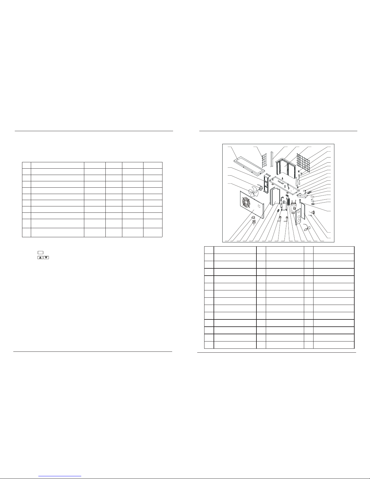
2.3 Discription of parts:
Compressor over-heat Compressor exhaust temp
is too high
Check signal cable of wire controller,
or change the w ire controller
Check refrigerant system.
1
2
3
4
5
6
7*
8
Turnround of defrosting
under heating mode
Defrost exit temp.
Temp. Of solenoid o valve switch on
Automatic restar ting
Mode(heating only/cooling & heating/
cooling only)
30~150min
5~45℃
3~15min
0/1/2
45min
25℃
3min
1
yes
time of exit defrost
under heating mode
yes
yes
yes
yes
yes
The unit's operation data can be set on the wire controller when the unit is on OFF
mode.
Please set according the below table:
Digit
0*
meaning
Max. setting water temp.
Range
0/1
(20~45/60℃)
default Adjust(yes/no)
yes
4. USAGE AND OPERATION
10
-7℃
1
0-1
0(no) 1(yes)
9
0/1 yes
Defrostin g start temp. -20~10℃
1
Water pump mode
*Remark:
All parameter can be set when the unit is OFF mode.
Press 3 seconds to enter in to settin g.
Press to change parameter.
All parameter can be revie w when the unit is ON mode,
but can not change.
Parameter 0:
0: temperature settin g range: 20~45 .
1: temperature settin g range: 20~60℃.
℃
0
3
Compressor protection exhaust temp. 70~110℃95℃
yes
0~25℃7℃
yes
M
Parameter 7:
0: alw ays open.
1: 30 seconds start before compressors start ing.
30 seconds stop aft er compressors stoppin g.
water pump stops when water temperature = settin g temperature.
fac tor y se tting
0
(20~45℃)
-7℃
15℃
F0 (150min)
3min
95℃
7℃
1
1
1
4.4 Operation data setting
2.SPECIFICATION
1 2 3 4 5 6 7 8 9 11 12 13 14 15 16
17
18
19
21
22
23
24
25
26
27
28
29
32
33
34353 6373839
40
41
42
30
10
20
31
1 Front panel 15 Power cord 29 Defrost sensor
2 Contr Right r d ol panel cover 16 ear boar 30 Filter
3 Wire controller 17 Refrigerant charge valve 31 One way valve
4 Verg Auxilliary capillary e board polyfoam 18 Pressure manometer 32
5 Verge board 19 Mouth of injecting gas 33 Capillary
6 Exhaust pipe 20 Terminal 34 Rear net
7 Solenoid valve 21 AC contactor 35 Condenser
8 Compressor 22 Cr Condenser top polyfoam eepage switch 36
9
High pressure interruptor (optional)
23 Electrical Box 37 Left carriage
10
Low pressure interruptor (optional)
24 Circuit Board 38 Left net
11 Four way valve 25 Motor Capacitor 39 Top cover
12 Gas returning pipe 26 Compre Motor bracket ssor capacitor 40
13 Titanium heat exchanger Frame Fan motor
27 41
14 Right size board 28 Feet 42 Fan
2.3 Explored view
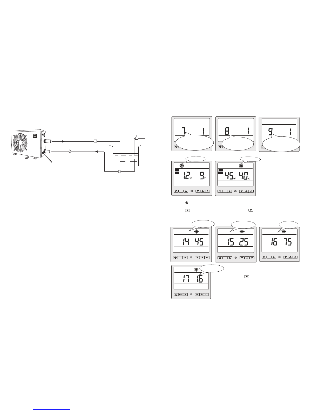
Installation items:
The factory only provides the main unit and the water unit; the other items in the illustration
are necessary spare parts for the water system ,that provided by users or the installer.
3.1 Installation illustration
Attention:
Please follow these steps when using for the first time
1.Open valve and charge water.
2.Make sure that the pump and the water-in pipe have been filled with water.
3.Close the valve and start the unit.
3.INSTALLATION AND CONNECTION
4
Chlori nato r cell
Wate r outle t
Pool
Valv e
Wate r
supply
Wate r inle t
Wate r pump
Sand fil te r
(or oth er ty pe fil te r)
4.3 How to choose Mode
Cooling mode Heating mode
M M
◎ Press “ M ” to choose mode(mode can be changed under running)
◎ Press “ ” to power on unit. Under running, the LCD displays the water setting temp,
water-out temp and current mode.
◎ Press ” to set temp. 1 degree higher, press ” to set temp. 1 degree lower.
4.4 How to know the current status?
Water outlet
temp. Ambient temp. compressor
exhaust temp.
M M M
Condenser temp.
◎Under running, press 3s to check the current status of the
unit. You can check water-out/ambient/compressor/condenser
temperature. If no buttons are depressed within 10 seconds,
the LCD will display water-setting/water-out temp.
When the unit is switched off, current water-out temperature
is displayed.
M
4. USAGE AND OPERATION
9
AUX
parame ter 9
Mode : 0(h eat ing onl y)
1(co oli ng an d heating)
2(he ati ng on ly)
fact ory s ett ing: 1
param eter 08
autom atic rest arting (0 /1)
facto ry settin g: 1
water p ump mode:
0: alre ady open
1: 30s st art befor e compres sor start
30s sto p after com pressor s top.
param eter 7
TEMP
SET
TEMP
SET
Con ne ct to po wer sup ply
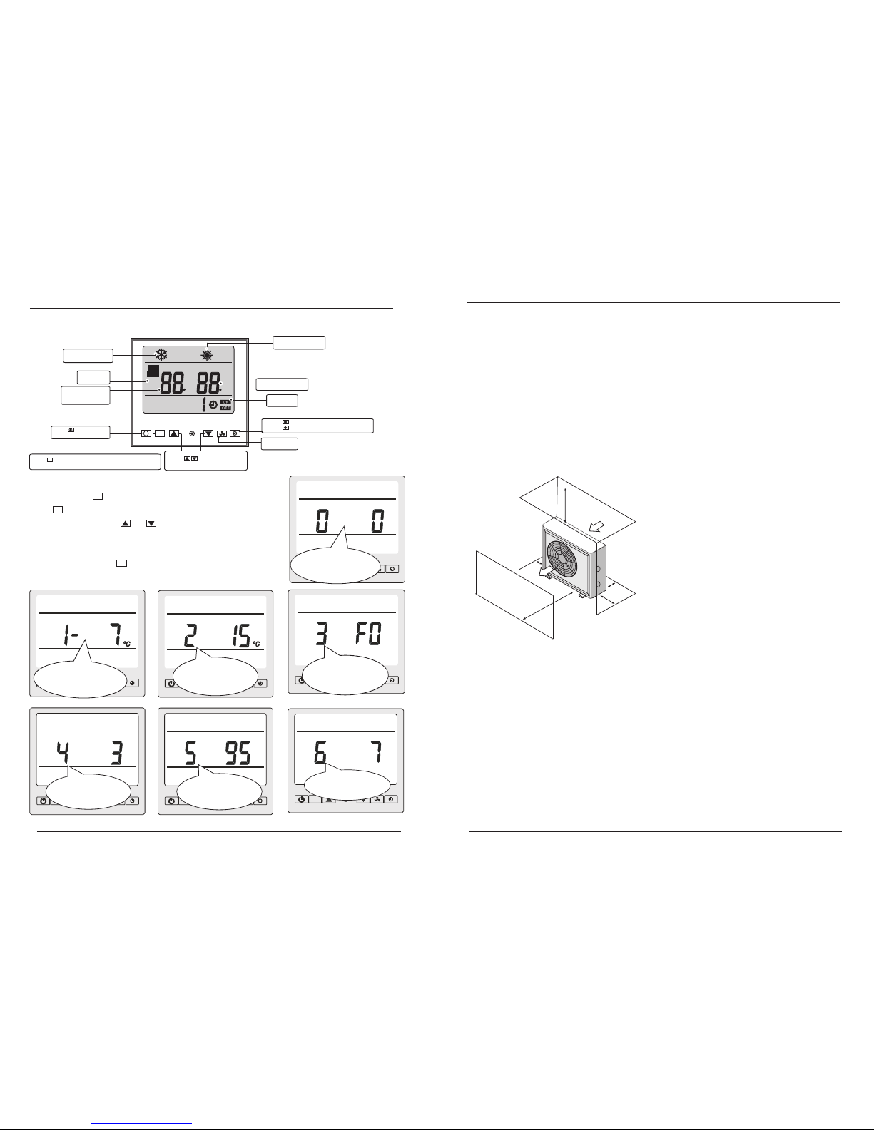
4.1 The Functions of the LCD Controller
Heati ng mo de
(‘SUN’sym bol )
M
TEMP
C
C
SET
Pres s to turn on an d
turn of f the u nits.
Press to set and ch eck
the operat ion d ata .
Press to start ti mer on / tim er off.
Press 3 seconds t o che ck te mpe rat ure.
LCD srceen
Press b utton to ch oose cool ing or heat ing mode
Press t his butto n 3 seconds t o set or revi ew data.
M
water o utl et temp.
Param ete r valve
Cooli ng mo de
(‘SNOW’sy mbo l)
4.2 How to set operation parameter
M
compressor protectio n
exhaust temperature
(70~110℃)
factory setting: 95℃
parameter 1
to set the defrosting sta rt
temp. under heating mod e
(-20~10℃) factory setti ng:-7℃
parameter 2
defrosting exit tempe rature
(5~45℃)
factory setting: 15℃
parameter 4
tim e of defrostin g
(3-15 min)
factory setting: 3 min .
parameter 5
◎ Standby status-press" "button 3s to enter operation parameter setting interface.
◎ Press" "again to start setting(parameter from 0-9, see Operation Parameter Table).
◎ Under parameter setting, press " " or " " to set data for parameter from 0-9.
◎ N
,
◎ running, you can press " " 3s to check current parameter, but data can t
be changed.
o press in 10s, the LCD will display water-setting/water temperature (under running)or
water temperature (unit stops).
Whilst
4. USAGE AND OPERATION
8
The unit will perform well in any outdoor location provided that the following three factors are present -
1. Fresh Air - 2. Electricity - 3. Pool filter piping
The unit may be installed virtually anywhere outdoors. For indoor pools consult
the supplier. Unlike a gas heater, it has no draft or pilot light problem in a windy area.
DO NOT place the unit in an enclosed area with a limited air volume, where the units
discharge air will be re-circulated. DO NOT place the unit to shrubs which can block air inlet. These
locations deny the unit of a continuous source of fresh air which reduces it efficiency and
may prevent adequate heat delivery.
3.2 Swimming Pool Heat Pumps Location
Normally, the pool heat pump is installed within 7.5 metres of the pool. The longer
the distance from the pool, the greater the heat loss from the piping. For the most part ,
the piping is buried. Therefore,the heat loss is minimal for runs of up to15 metres
(15 metres to and from the pump = 30 metres total), unless the ground is wet or the
water table is high. A very rough estimate of heat loss per 30 metres is 0.6 Kw-hour,
(2000BTU) for
ever y 5 difference in temperature between the pool water and the ground
surrounding the pipe, which translates to about 3% to 5% increase in run time.
3.3 How Close To Your Pool?
5
3.INSTALLATION AND CONNECTION
Air inlet
Air outlet
2 5 00mm
700mm
3 0 0mm
500mm
700 m m
coerc ive
defro sti ng
M
M
M
temperat ure o f so l enoid valve
switch on (0 ~25℃)
factory se tti ng: 7℃
M
paramet er 6
M
parameter 3
Turnro und of defrosting
(30 ~ 150m in.)
factor y setting: 150 min.
pa ram eter 0
to set the max setting wate r
temp. (20~45/60℃)
factory setting: 20~4 5℃.
water setting t emp .
Digit no. Timer o n
Timer o ff

3.5 Swimming Pool Heat Pumps Electrical Wiring
NOTE: Although the unit heat exchanger is electrically isolated from the rest of the unit, it simply
prevents the flow of electricity to or from the pool water. Grounding the unit is still required to protect
you against short circuits inside the unit. Bonding is also required.
3.INSTALLATION AND CONNECTION
3.6 Initial startup of the Unit
circulate water through the heat exchanger.
Start up Procedure - After installation is completed, you should follow these steps:
1. Turn on your filter pump. Check for water leaks and verify flow to and from the pool.
2. Turn on the electrical power supply to the unit, then press the key ON/OFF of wire
controller, It should start in several seconds.
3. After running a few minutes make sure the air leaving the top(side) of the unit is cooler
(Between 5-10 ℃)
4. With the unit operating turn the filter pump off. The unit should also turn off
automatically,
5. Allow the unit and pool pump to run 24 hours per day until desired pool water
temperature is reached. When the water-in temperature reach setting, The unit just
shuts off. The unit will now automatically restart (as long as your pool pump is running)
when the pool temperature drops more than 2℃below set temperature.
Water Flow Switch - the unit is equipped with a flow switch that turns it on when the pool
pump is running and shuts it off when the pump shuts off. This switch is the same type used
in all gas pool heaters and is factory adjusted for normal pool installations. If the pool
water level is more than a few feet above or below the thermostat knob of the unit, your
dealer may need to adjust it at initial startup.
Time Delay- The unit is equipped with a 3 minute built-in solid state restart delay included
to protect control circuit components and to eliminate restart cycling and contactor
chatter. This time delay will automatically restart the unit approximately 3 minutes after
each control circuit interruption. Even a brief power interruption will activate the solid
state 3 minute restart delay and prevent the unit from starting until the 5 minute countdown
is completed. Power interruptions during the delay period will have no effect on the 3
minute countdown.
NOTE- In order for the unit to heat the pool or spa, the filter pump must be running to
7
The unit has a separate molded-in junction box with a standard electrical conduit nipple already
in place. Just remove the screws and the front panel, feed your supply lines in through the conduit
nipple and wire-nut the electric supply wires to the three connections already in the junction box
(four connections if three phase). To complete electrical hookup, connect Heat Pump by electrical
conduit, UF cable or other suitable means as specified (as permitted by local electrical authorities)
to a dedicated AC power supply branch circuit equipped with the proper circuit breaker,
disconnect or time delay fuse protection.
Disconnect - A disconnect means (circuit breaker , fused or un-fused switch) should be located
within sight of and readily accessible from the uni, This is common practice on commercial and
residential air conditioners and heat pumps. It prevents remotely-energizing unattended equipment
and permits turning off power at the unit while the unit is being serviced.
3.4 Swimming Pool Heat Pumps Plumbing
The Swimming Pool Heat Pumps exclusive full flow titanium heat exchanger
requires no special plumbing arrangements or bypass. The water pressure drop is
less than 10kPa at max. Flow rate. Since there is no residual heat or flame
temperatures, The unit does not need copper heat sink piping. PVC pipe can be run
straight into the unit.
Location: Connect the unit in the pool pump discharge (return) line
downstream of all filter and pool pumps, and upstream of any chlorinators,
ozonators or chemical pumps.
Standard model have slip glue fittings which accept 40mm NB
PVC pipe for connection to the pool or spa filtration piping. By using a
50 NB to 40NB you can plumb 50NB PVC piping straight into the unit.
Give serious consideration to adding a quick coupler fitting at the unit inlet and outlet
to allow easy draining of unit for winterizing and to provide easier access should
servicing be required.
Condensation: Since the Heat pump cools down the air about 4 -5℃, water
may condense on the fins of the horseshoe shaped evaporator. If the relative
humidity is ver y high, this could be as much as several litres an hour. The water
will run down the fins into the basepan and drain out through the barbed plastic
condensation drain fitting on the side of the basepan. This fitting is designed to
accept 3/4" clear vinyl tubing which can be pushed on by hand and run to a suitable
drain. It is easy to mistake the condensation for a water leak inside the unit.
NB: A quick way to verify that the water is condensation is to shut off the
unit and keep the pool pump running. If the water stops running out of the
basepan, it is condensation. AN EVEN QUICKER WAY IS to TEST THE DRAIN
WATER FOR CHLORINE - if the is no chlorine present, then it's condensation.
3.INSTALLATION AND CONNECTION
6
To pool
From pump
PVC COUPLER
RECOMMENDED(Provided)
CONDENSATION
DRAIN
BARB FTG
Table of contents
Popular Swimming Pool Heater manuals by other brands

Raypak
Raypak VERSA 185B Replacement parts

Raypak
Raypak VERSA 155C Operating and installation instructions

aquatherm
aquatherm AT800 installation manual

Rheem
Rheem Raypak Professional Series Installation and operating instructions

Brilix
Brilix XHP 200 Installation and user guide

DLP
DLP 30HPRA-E-410 owner's manual

Raypak
Raypak 406A Installation and operation manual

Pahlen
Pahlen 141600 Installation instruction

emaux
emaux HP3.8B Installation instructions manual

infrasave
infrasave 4002-CB Installation & owner's manual

iGenix
iGenix IG9512 Instructions for use

Lochinvar
Lochinvar COPPER-FIN II CP 992 -2072 Replacement parts list


