FLARING FM 155E User manual

- 1 -
Operation Manual
FM155E MIG Welding Machine

- 2 -
Version
Due to product version upgrades or other reasons, the contents of this document are not regularly
updated. Unless otherwise agreed, this document is intended as a guide only and all statements,
information and recommendations in this document do not constitute any guarantee, expressed or
implied.
The pictures in this document are for reference only. If the picture is different from the real one, then
prevail in kind.
Contents
Contents......................................................................................................................................... - 2 -
1 Product brief introduction......................................................................................................... - 3 -
1.1 Summarize.............................................................................................................................................. - 3 -
1.2 Technical parameters.............................................................................................................................- 4 -
1.3 Accessories list.................................................................................................................................... - 5 -
2 Installation instruction............................................................................................................... - 6 -
2.1 Welding wire Installation steps:............................................................................................................- 6 -
2.2 MIG Torch explosive chart.................................................................................................................... - 7 -
2.3 Gas shielded welding Installation........................................................................................................ - 8 -
2.4 TIG Torch explosive chart ................................................................................................................... - 8 -
3 operating instructions............................................................................................................. - 10 -
3.1 Operation panel interface................................................................................................................... - 10 -
3.2 Welding operation instruction............................................................................................................. - 11 -
3.3 Polarity conversion joint...................................................................................................................... - 14 -
3.4 Welding environment and safety....................................................................................................... - 15 -
3.5 Welding problems and solution......................................................................................................... - 16 -
4 Trouble shooting and error checking.................................................................................- 17 -
5 Daily maintenance and checking....................................................................................... - 20 -
6 Attention................................................................................................................................. - 23 -
7 Appendix ⅠWelding parameter list.................................................................................. - 29 -
8 Service GUARANTEE......................................................................................................... - 31 -

- 3 -
1 Product brief introduction
1.1 Summarize
1IGBT Inverter
Technology
The principle is to use the single tube IGBT (the inverter frequency can reach
25-50KHz) to convert 50/60Hz to dc and then to high frequency and lower voltage
rectification,The pulse width modulation (PWM) output can be used for welding
high-power dc power supply ,due to switching power inverter technology is
adopted, the weight of the welder has dropped considerably, the conversion
efficiency of the whole machine is increased by more than 30%.
2SUPERIOR
PERFORMANCE
The machine can meet the requirement of gas protection welding. The gas
shielded welding machine is equipped with unique digital electronic reactor circuit.
The welding process of short circuit transition and mixed transition can be
controlled very precisely. It has excellent welding characteristics. Compared with
silicon controlled welder and tapped welder, it has the following advantages:
stable wire feeding speed, light energy, energy saving and no electromagnetic
noise。
It also has the characteristics of small splash,stable arc, deep pool and high
load.
3Wide Voltage
Our welding machine is equipped with power supply voltage compensation
device,The power supply voltage can continue to work when the rated voltage is
within 15% range.When using longer cables, in order to reduce voltage drop, use
a larger section of the cable is recommended or use the recommended
configuration length.
4Multifunction
The machine is a versatile product which include MIG gas, MIG gasless, Lift TIG ,
Stick welding and spool gun function. It has the advantages of high efficiency
and power saving, and it is suitable for welding of multi-metal and multi-process
requirements.
5Digital Control
The machine use full digital panel display ,Wire feeding speed and welding
voltage centralized regulation can be achieved. It is easier to adjust welding
parameters.Thanks to digital control, the machine comes with synergy software, it
match wire diameter, material and current. Excellent choice for freshman welder
and easier for welding professionals. Additional voltage and inductance setting for
professionals to find the precise welding performance for different project.
6Portability
The equipment applicable to family customers.Portable, light weight with only
12.8KG. 80% duty cycle on 116A, perfect for on-site job and DIY project.With
fluxed core wire, this welder can weld sufficiently without bringing heavy gas
cylinder. This is your ultimate welding stationary partner!

- 4 -
1.2 Technical parameters
Machine type FM 155E
Supply voltage (V) 1 phase AC 110V/ 220V±15%
Frequency (Hz) 50/60
Rated Max. input
current (A)
110
29 (MIG)
36.7 (STICK)
21.4 (TIG)
220
20 (MIG)
27.4 (STICK)
16.7 (TIG)
Output current
adjustment (A)
110V
30-100 (MIG)
30-100 (STICK)
30-100 (TIG)
220V
30-150 (MIG)
30-150 (STICK)
30-150 (TIG)
Output voltage (V)
110V
15.5-19 (MIG)
21.2-24(STICK)
11.2-14 (TIG)
220V
15.5-21.5 (MIG)
21.2-26(STICK)
11.2-16 (TIG)
No load voltage (V) 50±5
Duty cycle (%) 80
Power factor 0.7
Efficiency (%) 85
Wire feeder type All-in-one
Wire feed speed
(m / min) 2-15
Wire diameter (mm) 0.8/1.0
Insulation grade F
Enclosure protection
class IP21
Suitable plate
thickness (mm) 0.5-5
Net Weight (kg) 12.8
Overall dimension
(mm) 510×310×350

- 5 -
1.3 Accessories list
Order Number Pictures (Reference only) Name Qty
1FM 155E 1
2MIG Welding Gun Torch 1
3Welding Electrode Holder Set 1
4Earth Electrode Holder Set 1
5Gas hose 1
6Flux Cored Welding Wire 1
This equipment is mainly used in industry. In the indoor environment, the equipment may
produce radio interference. Please take precautions before use.

- 6 -
2 Installation instruction
2.1 Welding wire Installation steps:
The wire holder filled with wire installed on the wire feeder. The hole position of the wire plate
should be aligned with the fixed plug on the shaft.
The wire coil should be rotated and loosen the wire, to prevent the wire from loosening, the
new wire disk head is usually inserted into the fixed hole at the edge of the wire. In normal
use, to prevent the bending of the wire to be stuck, please cut this part of wire.
0.030”(0.8mm)/0.040”(1.0mm)diameter
4”(100mm 1kg)wire spool
According to the diameter of the wire, choose different wire feed roller.V roller for stainless
steel and carbon steel. Knurled roller for flux cored wire. Please match diameter notes on the
roller with the welding wire diameter.
Roller size: external diameter ∮25mm/ internal diameter ∮7mm/ height 7.5mm
- 7 -
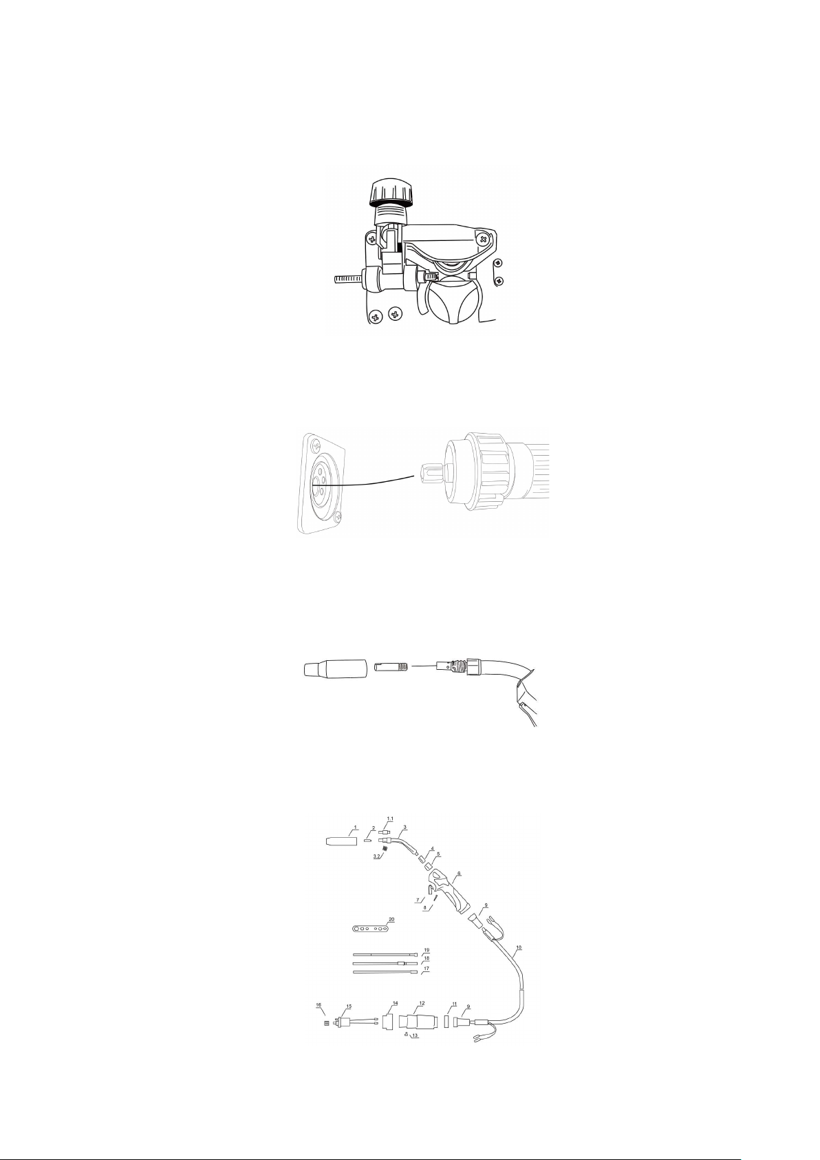
Loosen the pressure wheel nut, to pass through the guide wire tube into the wire feed wheel
groove, adjust the pressure wheel pressure welding wire, guarantee the welding wire is not
sliding, and not blocking while feeding the wire.
The welding gun is inserted into the output socket of the front panel and screwed
tightly.
And put the wire into the gun.
Unscrew the nozzle contact tip. And feed the wire through the torch. After the wire
successfully go through. Please install the contact tip. For fluxed core wire, please fasten
Ceramic nozzle, for solid wire please fasten copper nozzle.
2.2 MIG Torch explosive chart

- 8 -
Torch nozzel 1 and contact tip 2 are consumables. Please change when needed.
2.3 Gas shielded welding Installation.
MIG welding
The gas cylinder containing the carbon dioxide gas, mixture gas or argon gas decompression
flow meter is closely connected with the intake inlet of the machine.
Connect the machine rear gas fast plug and gas regulator with the gas hose in accessories.
LIFT TIG welding
The gas cylinder containing the argon gas decompression flow meter is closely connected
with the gas tube on torch.
2.4 TIG Torch explosive chart (Not included in standard accessories)

- 9 -

- 10 -
3 operating instructions
3.1 Operation panel interface
1Current display:Displays preset current and actual welding current.
2
MIG welding torch switch (Effective only in MIG 0.8/MAG 0.8/FLUX 1.0):The welding machine
only be operated with the Spool gun torch in the Spool gun torch mode; The MIG torch only be
used for welding in the MIG torch mode.Please check the switch status when using.
3This light is on in Stick mode
4This light is on in LIFT TIG mode
1
2
3
4
8
6
9
57
11
10

- 11 -
3.2 Welding operation instruction
On display
After open the power supply. 【Multifunctional data display window 】Flash 3 seconds (Or any
buttons and knobs on the front panel). Enter the welding mode saved last time.
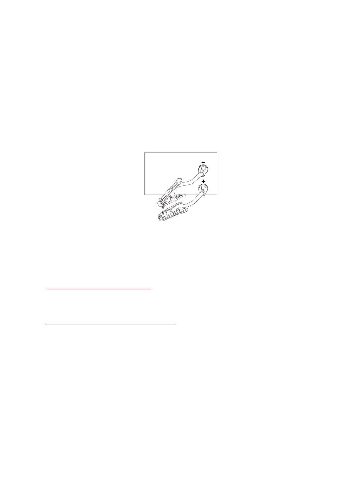
Stick Manual welding operation procedures
There are two ways to connect the dc welder normally:
Positive connection :Welding pliers connected to the negative pole, workpiece connected to
positive pole. Suitable for acid electrode.
negative connection: workpiece connected to the negative pole, Welding pliers connected to the
positive pole. Suitable for basic electrode.
The welding function is selected according to the welding process requirements of the workpiece,
5
Voltage minor adjust function. When the output current remains unchanged, the output
voltage can be adjusted in the range of - 3V to + 3V. Better welding effect can be obtained
according to personal habits and workpiece differences.
6Mode switch: , The function is cycled between STICK, LIFT TIG, MIG 0.8, MAG 0.8 and FLUX
1.0 with each click.
7
Current adjust function. Only the current is adjusted, but this machine is a digital machine.
The parameters of current, voltage and wire feeding speed have been matched. After
adjusting the current, other parameters follow the transformation and matching.
8
OC light :
When the welding load is overloaded and the output current of the machine is too large, the
internal temperature of the machine is too high, and the machine fault light will be on. This is
normal. The machine can recover after the heat dissipation becomes normal. Please restart
the power supply; When damaged, the fault light will be on, in this case, the machine is
abnormal and needs maintenance, please contact the supplier.
9AC 110V:This light is on when the input voltage is 110V
10 AC 220V:This light is on when the input voltage is 220V
11 MIG welding mode shift button:
MIG 0.8, MAG 0.8, FLUX 1.0.
- 12 -
incorrect data adjustment may cause arc instability, spatter and adhesion occur, we can change
the polarity joint for different workpiece as above.
Make sure the cable is connected to the soldering pliers and the quick plug,Connect the quick
plug to the corresponding fast socket ,And tighten it clockwise. The ground clamp clamps the
workpiece.
When the welding stop, operation [manual welding and gas protection welding switch key],
Manual welding indicator light, into manual welding mode.
In Manual welding mode, adjust【Multifunctional data adjusting knob】The welding current can be
changed, in【Multifunctional data display window】display. The welding current range is 30A to
maximum current 150A adjustment.
Operating procedures for MIG
gas protection welding
Welding wire Installation. (Refer to 3.1)
Please choose wire feed roller.V roller for stainless steel and carbon steel.
Connected with The gas cylinder. (Refer to 3.3)
insert the fast plug of the ground wire in the front panel on the fast socket.
Check wire operation:press torch switch, the wire feeder will feed the wire through the torch tip.
Select MIG mode on the front control panel(Make sure you are not in SPOOL GUN state). After
that, select the right material and diameter you are welding with. Adjust current according your
workpiece thickness.
To find the best welding performance and suitable for your welding habits. You may also adjust
voltage and inductance to build a perfect welding bead and penetration.

- 13 -
Solid wire
Gasless welding
Welding wire Installation. (Refer to 3.1)
Please choose wire feed roller. Knurled roller for flux cored wire.
insert the fast plug of the ground wire in the front panel on the fast socket.
Check wire operation:press torch switch, the wire feeder will feed the wire through the torch tip.
Select MIG mode on the front control panel(Make sure you are not in SPOOL GUN state). After
that, select the right material and diameter you are welding with. Adjust current according your
workpiece thickness.
To find the best welding performance and suitable for your welding habits. You may also adjust
voltage and inductance to build a perfect welding bead and penetration.
flux cored wire
Spool Gun torch welding
This machine can be connected to a Spool gun torch. (package does not include a spool gun).
The use of spool gun torch is similar to that of MIG gun, except that the wire is fed through the
wire feeding mechanism of the spool gun torch itself. In the spool gun mode, the feeding
mechanism of the original machine does not work.
Select spool gun mode on the front control panel or turn on the “Spool gun” switch at MIG mode.
(This toggle switch is in the wire feeding warehouse of the machine or near the “Mode” button).
Aluminum welding is supported in spool gun mode.
- 14 -
Solid Wire
flux cored wire
Operation of LIFT TIG function
Please follow installation draft to install the TIG torch and earth clamp. In Lift TIG welding mode,
adjust【Current adjusting knob】The welding current can be changed. The welding current range
is 30A to maximum current 150A adjustment.
TIG welding function are for thin workpiece welding or stainless steel welding. Usually choose Ar
gas as protecting gas.
Connect the gas hose with gas tube on torch.
Connect the TIG torch on negative plug.
Connect the Earth cable on positive plug.
Fault display:
OC light
When the welding load is overloaded and the output current of the machine is too large, the
internal temperature of the machine is too high, and the machine fault light will be on. This is
normal. The machine can recover after the heat dissipation becomes normal. Please restart the
power supply; When damaged, the fault light will be on, in this case, the machine is abnormal and
needs maintenance, please contact the supplier.
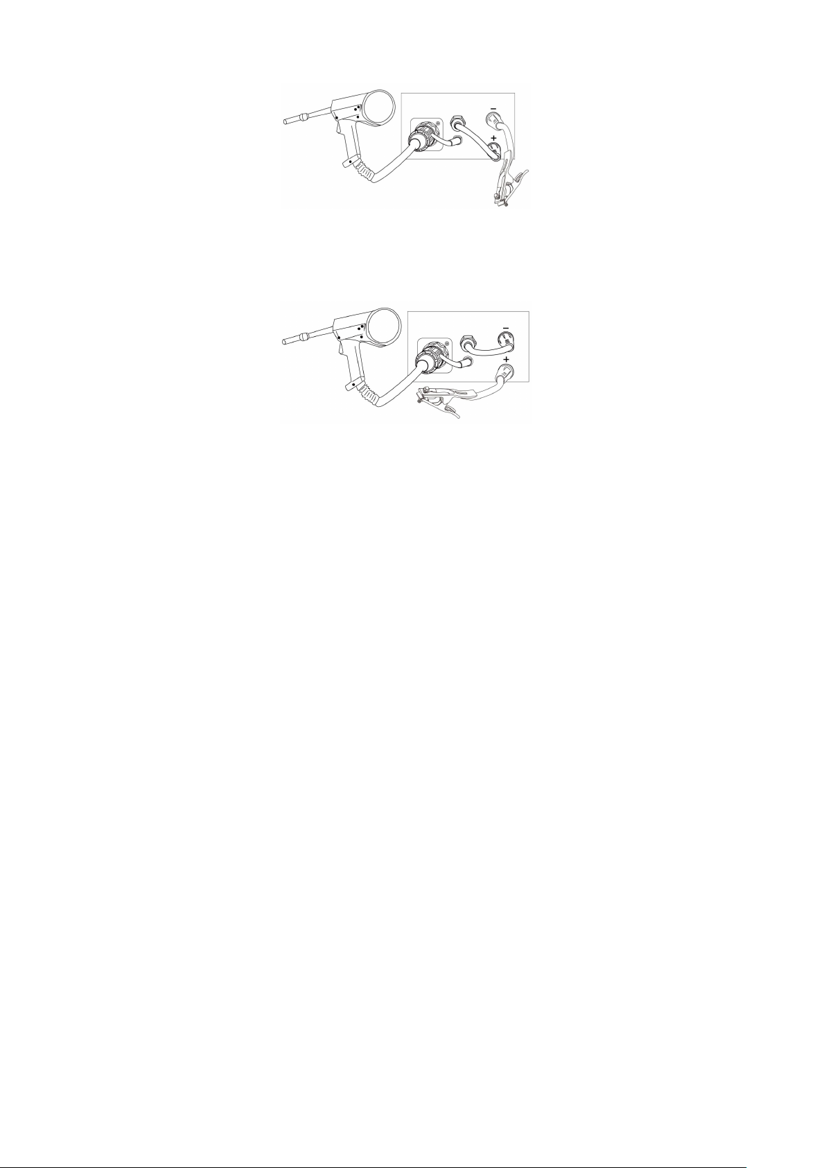
3.3 Polarity conversion joint
This machine has the polarity conversion; There are positive output terminal and negative output

- 15 -
terminal between wire feeder and wire spool; When use solid wire with gas protection, torch
socket should be connected to the positive output terminal, ground cable should be connected to
the negative output terminal; When use flux-cored wire, the ground cable should be connected to
positive terminal.
3.4 Welding environment and safety
Working surrounding
a) Welding should be carried out in dry surroundings. The air humidity level should not be higher
than 90%.
b) The temperature should be between -10C to 40C.
c) Don’t use the welding machines in sunshine or rain. Keep it off water.
d) Don't use the machines in the places of dust or corrosive air.
e) MIG welding should not be carried out in places with quick air flow.
Safety norms
Protection circuit of over-voltage, over-current and over-heat circuits are designed in the welding
machines. It will stop working automatically when the input voltage, output current or internal
temperature exceed the rated value. But if the machines are excessively used, such as with input
voltage higher than the rated, the machine might be damage. Please pay close attention to the
following matters.
a) Keep good ventilation!
The welding machines work with high welding current. Nature air flow can’t reach the requirement
of heat dissipation. So the fans are installed as cooling system to ensure stable performance.
Make sure the ventilation windows are not covered or blocked. The distance between the
machines and things around should not be less than 0.3m. Good ventilation is good for welding
performance and operational life.
b) Never over load!
Check the maximum rated current (according to the Duty Cycle chosen). Make sure the welding
current is never higher than the rated value. Over current running will obviously shorten the
operation life, even damage the machine.
c) Never over voltage!
The Input Voltage could be found in Technical data diagram. The auto-compensation function
will keep the welding current in the rated range. If the input voltage exceed the permissible value,
the machine would be damaged. Users should take protective measures in advance to avoid it.
d) Make sure earth connected before operation.

- 16 -
On the rear panel of welding machine, a screw for earth connecting would be found. It must be
ground connected with cable whose section is bigger than 6mm2before operation, to avoid accidents
caused by static or electricity leak.
3.5 Welding problems and solution
The phenomenon listed below may happen due to relevant accessories used, welding material,
surroundings and power supply. Pleas improve surroundings and avoid these problems..
Arc starting difficulty. Arc interruption happens easily:
a) Examine whether grounding wire clamp contacts with the work pieces well.
b) Examine whether each joint has improper contact.
The output current fails to reach rated value:
The deviation of power voltage from rated value may cause that the output current does no accord
with adjusted value. When the power voltage is lower than rated value, the maximum output
current may be lower than rated value.
The current can not keep stable during operation:
This situation may relate to the following factors:
a) The voltage of electric power network changes;
b) Serious interference from electric power network or other electric facilities.
Gas vent in welds:
a) Examine whether the gas supply circuit has leakage.
b) Examine whether there is sundries such as oil, dirt, rust, paint etc. on the surface.

- 17 -
4Trouble shooting and error checking
Notes: The following operations must be performed by qualified electricians with valid
certifications. Before maintenance, you are suggested to contact local distributor to verify
qualification.
Malfunctions Solution
The meter show nothing;
Fan does not rotate;
No welding output
Confirm the power switch is on.
Power supply available for input cable.
Check if the three phase commute bridge is damaged.
There is malfunction occurs in the supplementary power
source on control board (contact dealers).
The meter shows;
Fan works normally;
No welding output
Check if all the sockets in the machine are connected well.
There is open circuit or badness of connect at the joint of
output terminal.
The control cable on the torch is broken off or the switch is
damaged.
The control circuit is damaged.(contact to dealers)
the meter shows;
Fan works normally;
Abnormal indicator lights.
It might be over-current protection, please turn off the power
switch; restart the machine after the abnormal indicator light
winked.
It might be overheating protection, please wait for about 2-3
minutes until the machine renew without turn off the power
switch.
It might be multifunction of inverter circuit. (contact dealers)
Even the machine comes up with abnormal phenomenon such as welding unable, arc unstable or
bad welding effect, it is still early to judge that there is malfunction on the machine.
The above-mentioned abnormal phenomenon may be caused by some reasons. For example:
tight parts loosen, forgetting to switch on, wrong set up, cable broken and gas rubber pipe cracked,
etc. Therefore, please test and inspect these factors before deliver it back to the factory because
a large number of troubles may be easily solved probably.
For this reason, an initial diagnosis list for general welding troubles is shown below. A trouble
happened may be found in the column of “Abnormal items” on up-right of the list, please inspect
and maintain for the corresponding items which have “〇" mark in the column according to the
following list respectively.

- 18 -
Initial problems diagnose
Abnormal Items
Area and Item to be Inspected
and Maintained
No arc Starting
No Gas out
No Wire Feeding
Bad Arc Ignition
Unstable Arc
Dirt on Edge of Weld bead
Wire Stick to material
Wire
Stick
to
Conductive
Tip
Blowhole Formed
Distribution Boxes
(Input Protection
Devices)
Turn on power supply or not?
Fuse burnt out
Connection joint loose
〇 〇 〇 〇 〇 〇
Input Cable
Examine whether the cable
is cut off.
Connection joint loose
Over heat
〇 〇 〇 〇
Welding Power
Operation
Turn on power supply or not?
Phase Lacking 〇 〇 〇 〇 〇 〇 〇 〇
Gas Cylinder and
Gas Regulator
Turn on gas supply
Residual Amount of Gas in
the cylinder
Set value for flow
Connection joint loose
〇 〇
Gas supply hose
(the whole line
from the high
pressure cylinder
to the weld gun)
Connection joint loose
Gas hose damaged 〇
Wire Feeding
Device
Wire feeding wheel does not
match with the diameter of
wire in texturing tube
Crackle on wire feeding
wheel, groove blocked up or
defect
Too tight or loose of the
handle
Wire powder accumulated on
the inlet of SUS pipe
〇 〇 〇 〇 〇

- 19 -
Weld Gun and
Cable
1. Weld gun cable rolled up
or over curved
2. Adaptability of conductive
tip, wire feeding pipe and
cable diameter Worn,
blocked up or deformation,
etc.
〇 〇 〇 〇
Body of weld gun
Loose connection of
conductive tip, nozzle and
nozzle contactor
Contactor of weld gun body
is not plunged in or tightened
well
〇 〇
Power supply cable
of weld gun as well
as cable of switch
control
Break off (bending fatigue)
Damaged by weighted drop 〇 〇 〇 〇 〇
Surface Condition
of Parent material
and length that
wire stretches out
Oil, dirty, rust and paint
residues
Too long length of wire
stretched out
〇 〇 〇 〇 〇
Output Cable
Cross-section of cable that
connects to parent material
is not enough
Loose connection of (+),
(-)output cable
Bad electric conductivity of
parent material
〇 〇 〇
Lengthened Cable
Cross-section of cable is not
enough
It is rolled up or folded
〇 〇 〇 〇
Work Condition for
Welding
Welding current, voltage,
angle of weld gun, welding
rate and wire length
stretched out should be
confirmed once again
〇 〇 〇 〇 〇
- 20 -
5 Daily maintenance and checking
Daily maintenance
a) Remove dust regularly with dry compressed air. If the welding machine is used in
surroundings with heavy smoke and polluted air, it is necessary to remove dust at least one
time one month.
b) The pressure of compressed air shall fall to required level to prevent damage to small
components in the machine.
c) Examine inside electric joints and ensure perfect contact (Especially plugs and sockets).
Fasten the loosing joints. In case of oxidation, remove oxide film with sand paper and connect
again.
d) Prevent water from entering into the machine and prevent the machine from getting moist. If
any, blow and dry. Measure the insulation with megohmmeter to make sure it is qualified to
use.
e) If the welding machine is not used for a long time, pack the machine in original package and
store in dry surroundings.
f) Every time the wire feeder operates for 300hours, grind the electrical carbon brush and clear
up the armature commutator. Rinse speed reducer, apply 2# Molybdenum Disulfide lubricant
to the turbine, whirlpool rod and bearing.
All the maintenance and testing must be carried out when the power supply is totally cut
off. Please make sure the power is off before opening the closure.
Daily checking
WELDING POWER SUPPLY
Position Checking keys Remarks
Control panel
Operation, conversion and installation of the switch
Check the state of the power indicator light
Lead to unstable arc and
wire sending
Cooling fan Check if the fan state and the sound is normal or not
Clean the residue and
check the reason and
solve it
Power part
Check if there is abnormal liberation and sound
when the power is on
Check if there is smell when the power is on
Whether the outside color change or get warm
This manual suits for next models
1
Table of contents
Popular Welding System manuals by other brands


Weco
Weco POWER PULSE DIGITAL 405d instruction manual

Jefferson
Jefferson JEFTIG GT Series Operator's manual

Hypertherm
Hypertherm XPR300 instruction manual

Abicor Binzel
Abicor Binzel ABIMIG A155 operating instructions

Parweld
Parweld XTM 221Di Operator's manual

Miller Weldmaster
Miller Weldmaster 112 Extreme manual