FlashPoint Studio 400 Monolight User manual

Studio 300/400 Monolight
with Built-in R2 2.4GHz Radio Remote System
FPLFS300B/ FPLFS400B

2
Thank You for Choosing Flashpoint!
The new Flashpoint Studio300 R2 and Studio400 R2 are 300 and 400 watt second monolights,
designed to be compact AC studio members of the R2 Family of wireless radio controlled ashes.
The small units deliver GN 190 (ft) / 58 (m) - Studio300, and GN 213 (ft) / 65 (m) - Studio400, respec-
tively, with standard Bowens reectors and modiers. Add the pro quartz modeling light feature
and the picture is complete. The incredible amount of power and control in these compact and
lightweight ashes, make this design a rst choice of all photographers with an eye for exible mul-
tiple light set up in a studio or home environment. You can use them on household circuits without
blowing fuses. And the same R2 Wireless Remotes that command the Flashpoint XPLOR600,
Streaklights, Zooms, eVOLV200, Rapid and Mini’s, work in total harmony with the Studio Series to
bring the same R2 ease of control to the studio based world of photography. The Studio300 R2 and
Studio400 R2 have a max recycle times of 2.5 and 2 seconds, respectively, and reliability that only
AC can guarantee.
Please feel free to contact us at Brands@Adorama.com .
CAUTION
Overheating will occur if it is used for more than 30 continuous full power ashes.
Please allow the unit to cool down to prevent da mage.
Do not keep using the modeling lamp for a long time without supervision.
Flammable accessories attaching to the head, e.g. a softbox, may get toasty.
When using a snoot, do not keep the modeling lamp on for a long time or re too
frequently, not over six times per minute. Overheating may result in damage to the strobe
housing or light.
Do not touch the two terminals of the tube outlet as there is high voltage inside.
Wear insulated gloves before replacing the tube or modeling lamp.
Avoid sudden impacts as this can damage the ash tube and/or modeling lamp.
Do not ash directly in the face at close distances (especially those of babies),
as it may cause visual impairment.
Disconnect from the power supply when it will not be used for an extended period.

3
For Your Safety
To prevent damage to the product or injury to you or to others, read the following
safety precautions in their entirety before using this device. Keep these safety
instructions where users can read them for ready reference.
Do not disassemble or modify
There are high-voltage components inside the unit. Failure to observe this precaution could
result in electric shock or product malfunction. Should the product break open as the result of a
fall or other accident, send the defective back to the authorized service center for inspection and
maintenance.
Keep dry
Do not handle with wet hands, immerse in water, or expose to rain. Failure to observe this precau-
tion could result in re or electric shock.
Keep out of reach of children
This device contains small parts that may pose a choking hazard. Consult a physician immediately if
a child swallows any part of this device.
Do not expose to high temperature
Do not leave the device in a closed vehicle in the sun or in other areas subject to extremely high
temperature. Failure to observe this precaution could result in re or damage to the housing or
internal parts.
4
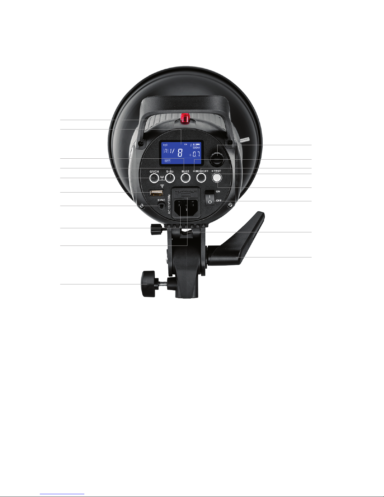
1. AC Power Cord Socket
2. Sync Cord Jack
3. Power Switch
4. Open Flash Test Button
5. Modeling Lamp Button (ON/OFF)
6. Slave Model Button (S1/S2)
7. Group/Channel Selection Button
8. BUZZ (Audio Signal) Button
9. R1 Wireless Control Port
10. LCD Display
11. Optical Slave Light Sensor
12. Modeling Lamp Indicator
13. Power Ready Indicator
14. Select Dial + SET Button
15. Fuse
16. Stand Mount Knob
17. Umbrella Shaft Input
18. Head Tilt Lock
NAMES OF PARTS
14
12
5
13
4
3
17
18
11
10
8
6
7
9
2
1
15
16
5
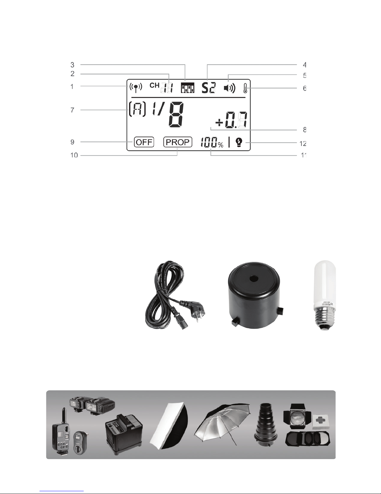
1. R2 2.4G Wireless Transmission
2. Wireless Channel Selection
3. Wireless Channel Switch Code
4. Slave Model Indicator
5. Audio Beep
6. Temperature Alarm Display
7. Wireless Group Designation
8. Flash Output
9. Modeling Lamp is OFF
10. Modeling Lamp is in the PROP mode
11. Modeling Lamp shows the power in
percentage
12. Modeling Lamp is OFF when the
ash is triggered, ON upon recycle
LCD Panel
1. Power Cord
2. Lamp Cover
3. Modeling Lamp
4. Instruction Manual
Separately Sold Accessories
The product can be used in combination with the following accessories sold separately, so as to
achieve best great lighting: R2T or R1 remote control, AC Power Inverter, Glow Softbox, Umbrella,
Light Stand, Barndoor, Snoot, etc.
LCD Panel

6
Operations
1. Remove the lamp cover. Install the modeling
lamp and attach a standard reector.
To detach the standard
reector, press the release button on the ash head
and turn the standard reector
counterclockwise.
2. Attach the ash unit onto an
appropriate light stand. Adjust the mounting
bracket (16) and make sure it is tightened.
Use the (18) to adjust the ash to a desired
direction. Umbrella shaft channel (17) Head
tilt lock accommodates most umbrella diameters.
Power Connection
Firmly insert the power cord and connect the ash to an AC power source. Turn on the power
switch (3).
Modeling Lamp
Short press the Modeling Lamp Button (5) to choose the modeling lamp’s mode (OFF/ON,
PROP and Percentage); and long press the Modeling Lamp Button (5) to set the lamp to INTER-
MITENT Mode, linking the modeling lamp to indicate the completion of recycle of the ash.
Modeling lamp will be turned o automatically after 4 hours, as a safety measure.
When there is ammable accessory mounted on the ash unit, do not keep
the modeling lamp on for an extended time, as there is no internal fan.
Without ventilation within the accessory, a cool down period is recom-
mended.
17
18

7
Power Output Control
The Select dial (14) varies the power output, setting the light requirements as needed. The power
is adjustable in thirds of a stop from 1/16 to 1/1, in increments of tenths of a stop, clearly shown
on the LCD display (10).“--”on the display indicates that the ash triggering function is turned
o. Press the Test button to discharge power quickly when the ash output is adjusted from high
to low. The red ready light (13) ashes to indicate energy bleed status until the power setting is
reached.
Test Button
To re the ash without taking a picture, press the test button (4). It can also help adjust the ash
brightness when combined with the select dial (14). Press the SET button and turn on the ash to
sample the power of the light.
Sync Triggering
The sync cord jack (2) accepts a Φ3.5mm plug. Insert a trigger cord plug to re in sync to an
attached camera’s PC socket.
GR/CH Button
A short press on the GR/CH button can adjust the monolight’s wireless group. When the group
indicator on the LCD panel is blinking, turn the select dial to change. A long press on the GR/CH
button adjusts the wireless channel. When the channel indicator on the LCD panel is blinking, turn
the SELECT dial to change. Press the SET button (14) to set the value. Make sure that the Transmit-
ter and Slave units have the same values.
Optical Slave Trigger Modes
Three optical slave triggering modes are available and can be set by pressing the slave mode
button (6).
• No optical slave control: S1 or S2 is not displayed on the LCD panel, indicating the slave trigger-
ing function is shut down.
• First Flash Trigger: S1 is displayed on the LCD panel, indicating the strobe will re immediately
when the sensor sees another ash re. In this mode, the ash can function as an slaved lamp,
oering various eects of light and shadow.
• Intelligent Slave/Second Flash Trigger: S2 is displayed on the LCD panel, indicating the optical
sensor will ignore the pre-ash sent by a TTL ash and re on the second ash of a TTL speedlite.
In this mode, the ash can function as an slaved light to a TTL based system. The light output is
always set manually on this Studio 300/400 R2 monolight.
8
Buzz Function
The sound button (8) is used for turning on the audible tone for signaling the ready status of the
ash after recycling. The sound symbol is displayed on the LCD panel when active. A brief tone is
heard indicating ready to re status.
Key Button Combinations
Pressing the the GR/CH button and the S1/S2 buttons simultaneously turns the built-in R2 wireless
receiver ON or OFF. If there are no wireless and channel indicators displayed on the LCD panel, the
built-in wireless receiver is o. The presence of a Channel indicates that the R2 wireless receiver is
on. Press the S1/S2 and BUZZ buttons simultaneously to recover factory settings.
Alarm Display
E0 The temperature sensor is not connected.
E1 A recycle error related to capacitance and voltage regulation.
E2 Components are over safe temperature limits.
E3 Discharged capacitance and voltage rating >+10%. Audible alarm sounds, ringing twice per
second. Press SET button to stop alarm signal.
Memory Function
The device is equipped with a memory function for retaining all the settings, 3 seconds after you
set it. When turning on the ash the next time, the panel setting will be set the same as the last use.
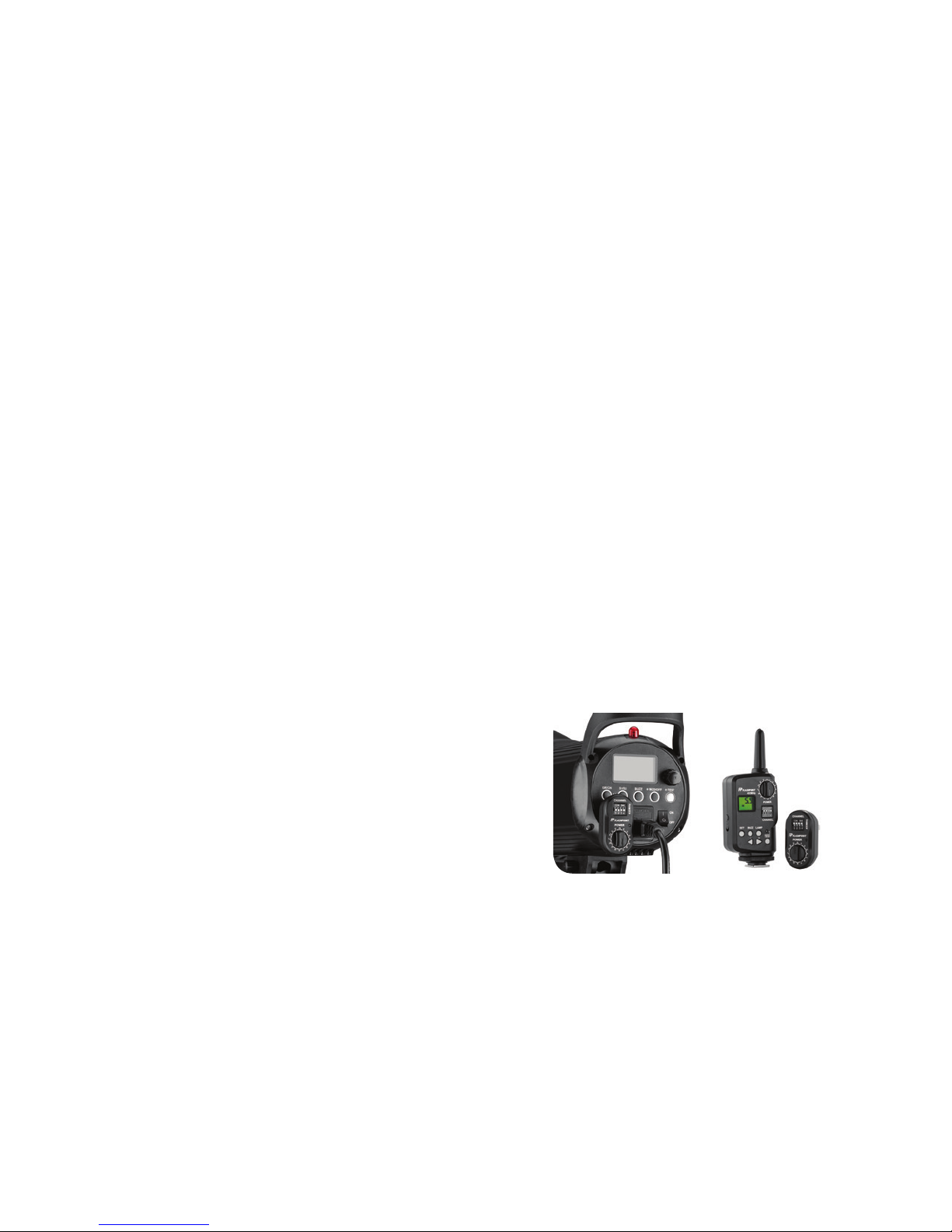
R1 Wireless Control Function
The ash unit has a built-in R2 2.4G wireless receiver, but R1 devices can be used with the Flash-
point R1 transmitter and receiver (FPRRSL) set.
• The ash unit has a Wireless Control Port (9) that can
accept R1 remote control of the ash, modeling lamp
and audio signal, as well as adjust the ash output
level, and other functions.
• To control the ash wirelessly, you need the Flashpoint R1 Transmitter and Receiver remote control
set (on-camera and on-ash). Insert the USB end into the Wireless Control Port (9) on the ash and
insert the transmitter device into the camera hot shoe. Settings made on the hotshoe-mounted
transmit and receive signals will be
wirelessly communicated to the ash. The camera shutter-release button transmits your com-
mands to trigger the ash.
• For full instructions on the use of R1 series remote control, see the The Flashpoint R1 Transmitter
and Receiver Set (FPRRSL) user manual.
9
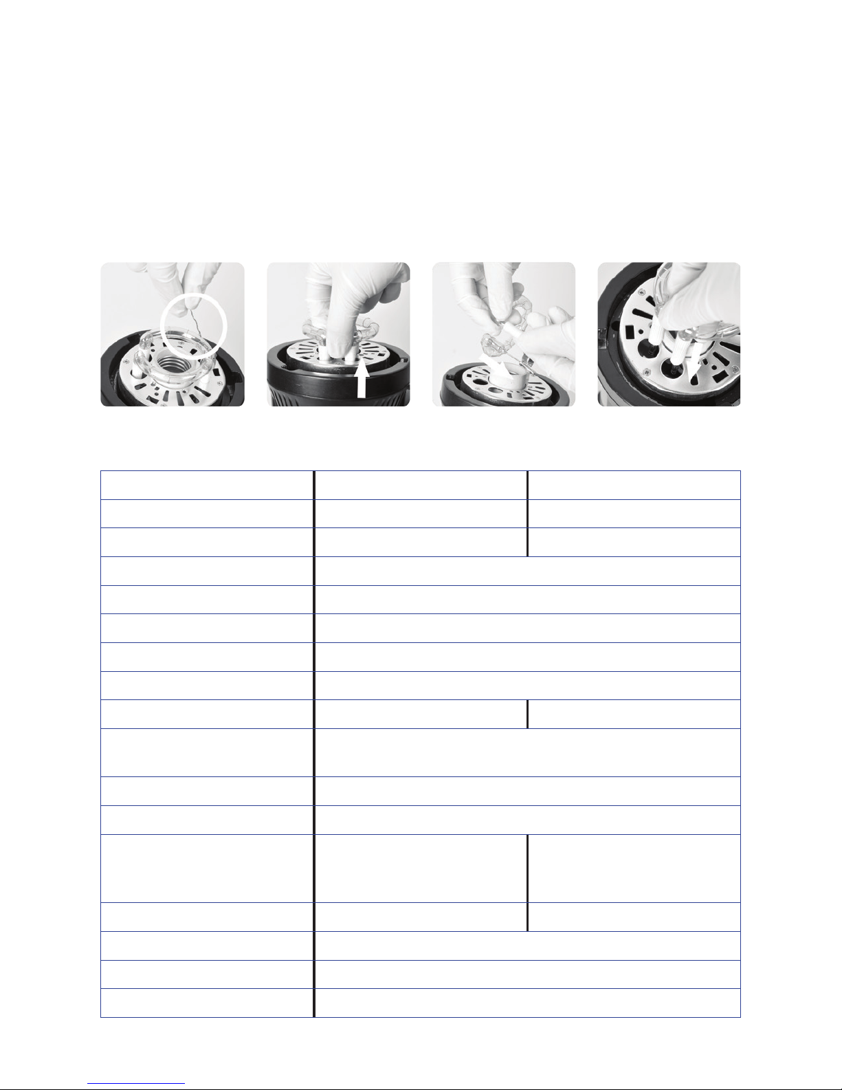
Flashtube Replacement
Turn o the power and remove the power cord before replacing the ash tube. Note the ground
wire wrapped on the ashtube. Wear gloves to loosen the metal wire on the tube. Keep a rm
hold on the two contact prongs of the ash tube and pull out the tube gently. Remove the contact
prong sleeves from the old tube and put them on the new one. Hold two prongs of the new tube,
and carefully directly towards the two copper socket outlets on the body, then push them carefully
and rmly into place. Replace the ground wire on the ash tube as on the original tube.
TECHNICAL DATA
Flashpoint Model Studio 300 Monolight Studio 400 Monolight
Max Power (Ws) 300Ws 400Ws
Guide Number( ISO 100) 190ft / 58m 213ft / 65m
Color Temperature 5600±200k
Operating Voltage AC200-240V/50Hz or AC100-120V/60Hz
Power Output Control From 1/16 (6.0) to 1/1 (10.0) full power in tenths of a stop increments
Modeling Lamp (W) 150W
Modeling Lamp Level 5%~100%
Recycle Time 0.4~2.5s 0.4~2s
Triggering Methods R2 Wireless built-in, Sync cord, Test button, Optical slave triggering,
R1 Wireless USB port
Flash Duration 1/2000~1/800s
Fuse 5A
Dimension Flash diameter Φ 5.0in/12.7cm.
8.1in/20.6cm
Length 13.4in/34cm
Flash diameter Φ 5.0in/12.7cm.
9.1in/23.2cm
Length 15in/38cm
Net Weight Approx. 4.1lb / 1.9kg Approx. 4.6 lb / 2.1 kg
Groups 16 [A-F and 0-9]
Channels 32
R2 2.4GHz Radio Range 328ft/100m

10
MAINTENANCE
Turn o the device and disconnect it from mains immediately when it works
abnormally and nd out the reason, for the malfunction.
Avoid sudden impacts.
The unit should be kept should be kept dust free.
It is normal for the lamp to be warm when in use. Avoid continuous
ashes if unnecessary.
Maintenance of the ash must be performed by our authorized maintenance department which
can provide original accessories. The ashtube and the modeling lamp are user-replaceable.
Replacement tubes and lamps can be obtained from the Adorama/Flashpoint.
This product, except consumables e.g. ash tube and modeling lamp, is supported with a one-year
warranty.
Unauthorized service will void the warranty.
If the product had failures or was exposed to moisture, do not use it until it is repaired by profes-
sional.
Disconnect the power when cleaning the ash or when changing the
ashtube / modeling lamp.
Changes made to the specications or designs may not be reected in this manual.
Question about our product line? Need Product Support?
We are proud of our products and celebrate our customers. We are with you,
from product selection to everyday use. Be secure with your purchase and reach
us as you need.
Call: 212-647-9300
Address: Adorama Brands, 42 West 18th Street, New York, NY 10011
Our web site contains a wide range of Support and FAQ pages with valuable
technical assistance.
Flashpoint is a registered trademark of ADORAMA CAMERA.
© 2017 Adorama Camera, Corp. All Rights Reserved.

11
ONE YEAR FLASHPOINT LIMITED WARRANTY
Flashpoint warrants to the original purchaser that your Flashpoint Studio 300/400 R2
Monolight shall be free from defects in material and workmanship for the period of
one (1) year from the date of purchase (or delivery as may be required in certain
jurisdictions), or thirty (30) days after replacement, whichever comes later.
Flashpoint’s entire liability and your exclusive remedy for any breach of warranty
shall be, at Flashpoint’s option, to repair or replace the hardware, provided that the
hardware is returned to the point of purchase or such other place as Flashpoint may
direct with a copy of the sales receipt or dated itemized receipt. Flashpoint may, at
its option, replace your product, oer to provide a functionally equivalent product,
or repair any product with new, refurbished or used parts as long as such parts are in
compliance with the product’s technical specications. Any replacement hardware
product will be warranted for the remainder of the original warranty period or thirty
(30) days, whichever is longer, or for any additional period of time that may be
applicable in your jurisdiction. If the product has been discontinued, the warranty
provider reserves the right to replace it with a model of equivalent quality and
function.
This warranty does not cover problems or damage resulting from accident, abuse,
misapplication, or any unauthorized repair, modication or disassembly, improper
operation or maintenance, normal wear and tear, or usage not in accordance with
product instructions or connection to improper voltage supply, use of consumables,
such as replacement batteries, not supplied by Flashpoint, except where such restric-
tion is prohibited by applicable law.
Except where prohibited by applicable law, this warranty is nontransferable and
is limited to the original purchaser and the country in which the product was
purchased. This warranty gives you specic legal rights, and you may also have other
rights, including a longer warranty duration that may vary under local laws.
To start a warranty claim contact the Flashpoint Customer Service Department to
obtain a return merchandise authorization (“RMA”) number, and return the defective
product to Flashpoint, along with the RMA number and proof of purchase.

This manual suits for next models
1
Table of contents
Other FlashPoint Lighting Equipment manuals


