FLATLIFT Pop-Up User manual

P.01
Operating Manual
Outperform. Outlast.
Operating Manuel
Operating Manual

P.02
Operating Manual
Outperform. Outlast.
CONTENTS
CONTENTS
C.01 INTRODUCTION
C.02 FEATURES
C.03 PRODUCT DIMENSIONS
C.04 INITIAL PRODUCT SET UP
Set-up P.06
Images P.07-08
K.05 PRODUCT INTEGRATION
C.07 TROUBLE SHOOTING
C.08 LEGAL NOTICE
C.06 RECOMMANDED INSTALLION
Example of console integration P.12
Example of back of sofa integration P.13
CONTENTS

P.03
Operating Manual
Outperform. Outlast.
CONTENTSCONTENTS
Intended Use
The product serves the lifting and lowering of LCD and plasma TV equipment.
All company names and product names are trademarks of the corresponding owner. All rights reserved.
The scope of supply can vary depending on the product and the range of xtures and ttings. Please
check that the product supplied is complete and inform us within seven days of delivery if the scope of
supply is not complete.
Safety and Hazards Recommendations
Please read this chapter carefully and follow all of the instructions provided. In this way you are able to
guarantee the reliable operation and a long lifespan for your lift system. Keep the operating manual in a
safe place.
In the event of damage which is the result of non compliance with this operating manual, all claims pertai-
ning to the guarantee are null and void. We generally accept no responsibility for secondary damage.
We accept no responsibility for damage to objects or persons which is caused by the inappropriate use of
the product or through ignoring the safety instructions. In such cases, all claims pertaining to the guaran-
tee are null and void.
Quality
In the choice of our components, our primary focus was on ensuring a high level of functionality,
straightforward use, safety and reliability.
We would like to thank you for the trust you have placed in our Flatlift brand products.
We can help you with your installation through providing individual customer care.
For safety reasons, the unauthorized conversion and/or changing of the product is not permitted. Do not
dismantle this product.
This product is not a toy and does not belong in the hands of children.
Do not allow the product to become damp or wet.
Do not leave the packaging material lying around as children may choke if they swallow it.
The product will be damaged if it is dropped, even from a low height.
Before using the product for the rst time, please check that the free raising and lowering of the Flatlift
including the mounted TV equipment is possible and ensure a collision-free run.
INTRODUCTION
INTRODUCTION
C.01:
For legal reasons and insurance purposes, your Flatlift is equipped with an ‘automatic safety
device’.
This means that the button which controls the raising and lowering must be pressed down all
the time.
The system stops and remains in the same position as soon as you let go of the button.
P.04
Operating Manual
Outperform. Outlast.
* not relevant
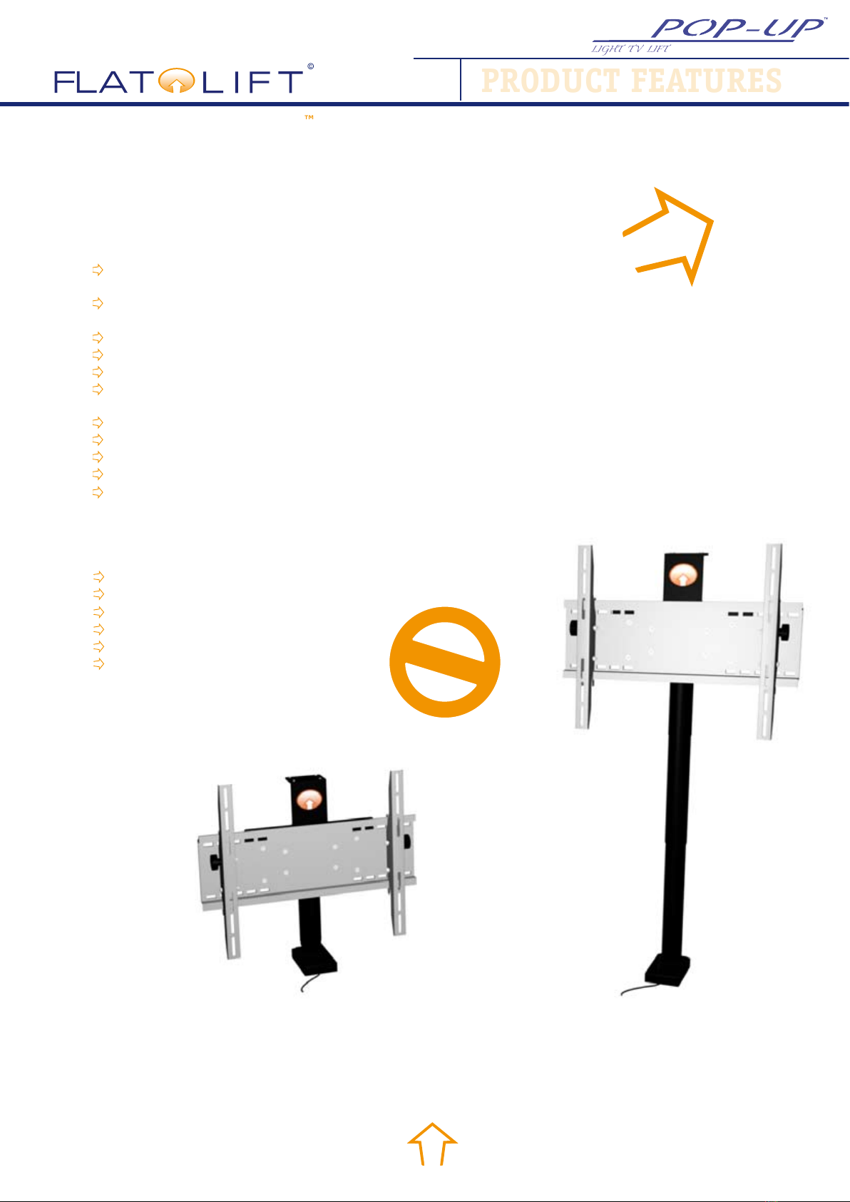
Features:
Installation base
W=177 mm D=97 mm
Installation dimensions, Flatlift
W=785 mm D=157 mm H=603 mm
Lift 635mm
Lifting speed 30 mm / sec
TV weight max. 35 kg / 350N / including cover (P.011)
TV size 26“-42“ (inches)
(max. TV size possible in mm: W = * , H = max. 586, D = *)
Power-on time 18%/h
Can be tilted (-15° manual).
Soft Start / Soft Stop
Low noise level < 45 dB
Environmental temperature from +5°C to 40°C
Flatlift Pop-Up Light TV Lift
Cableset
Universalretainer up to 42“
IR Remote Control
Touchpanel
IR eye
Scope of supply:
BUY NOW
L
I
F
E
T
I
M
E
R
e
p
a
i
r
c
o
s
t
l
i
m
i
t
5
y
e
a
r
s
f
u
l
l
s
e
r
v
i
c
e
GUARANTY
C.02:
PRODUCT FEATURES
PRODUCT FEATURES

P.06
Operating Manual
Outperform. Outlast.
Abb.1
2
3
5
4
1
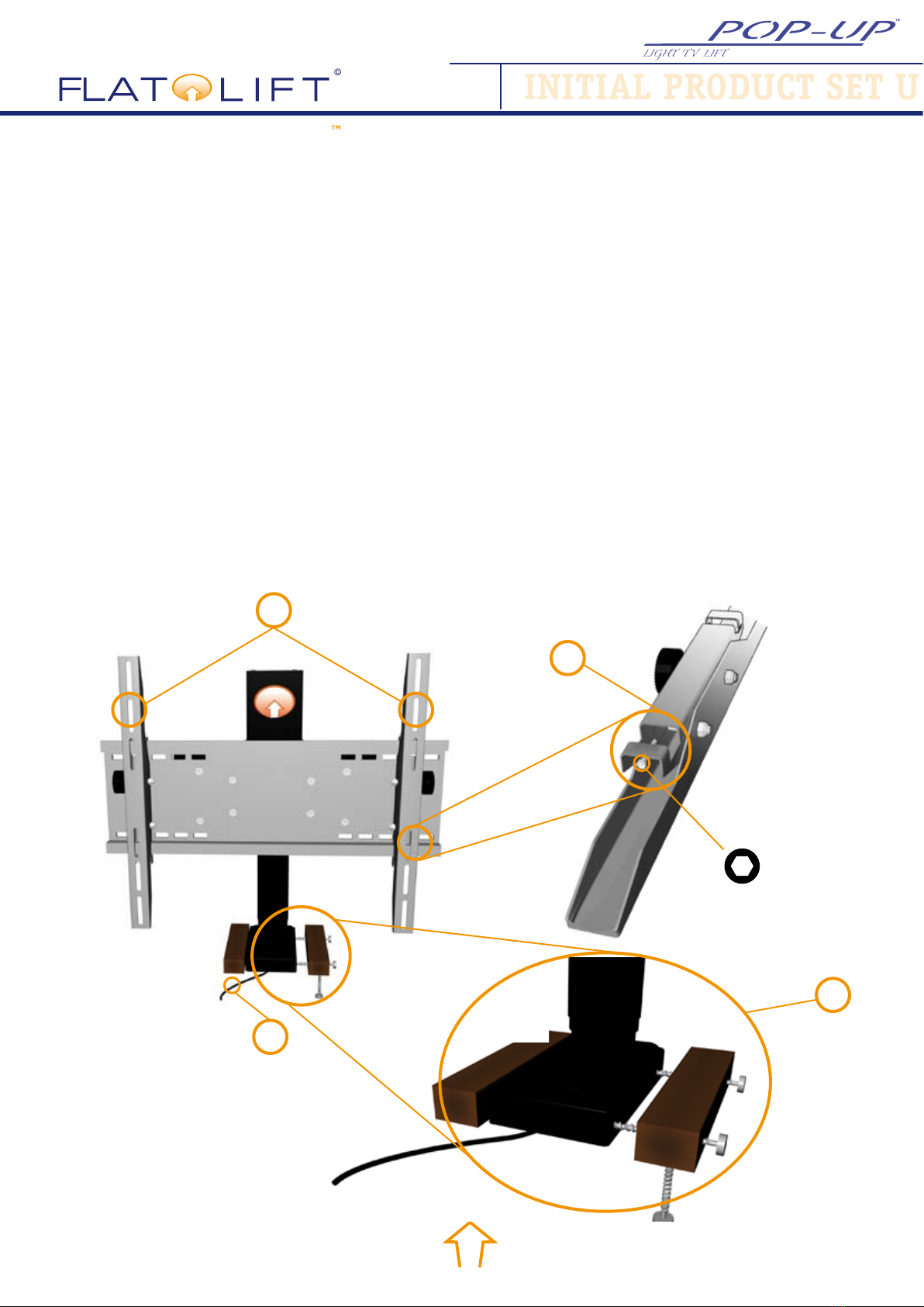
INITIAL PRODUCT SET U
INITIAL PRODUCT SET UP
C.04:
Initial set up:
1. First tting left and right an wooden beam on your Flatlift (image 1, no. 1) and screw the wooden
beams onto the subgrade, to t the Flatlift system.
2. Connect the Flatlift (image 1, no. 3) with the motor cable (P.07, image 3) and then the motor cable
with the conrol box (P.07, image 2, no. 5).
3. Now plug-in the RJ45 connector of the touchpanel (p.07, image 2, no. 6) into t the control box.
4. First connect the power cable (P.08, image 5) into the control box and then connect the power cable
in the power supply voltage.
5. Connect the IR eye (P.07, image 4b, no.9) with the touchpanel. Be sure, that the IR eye (p.07, image
4b, no. 9) is not hidden. Place the IR receiver well visibily, because it is very important for the connec-
tion between your IR remote control and IR eye.
6. Your Flatlift ist now ready.
7. Now you can assamble the TV onto the Flatlift system (image 1, no. 2)and save your TV with the
safty screw (image 1, no. 4).
8. And that´s it. Now you can use your IR remote control comfortable with the buttons „up“ and „down“
(P.08, image 10, no. 10 and no. 11) to control your Flatlift system.


P.09
Operating Manual
Outperform. Outlast.
C.05:
image 2
INITIAL PRODUCT SET U
PRODUCT INTEGRATION
PRODUCT INTEGRATION
Image 1
Lid variation 1:
A lid closing mechanism on the
rear section of the unit incor-
porating spring damped hinges
which opens automatically when
the Flatlift moves upwards.
Different lid closing solutions are
available depending on the reali-
sation of the project (image 1).
The A/V installer which is ins-
talling the Flatlift thus enjoys
exibility and can also change
the lid solution again at a later
time. When the Flatlift retracts,
the cover closes softly thanks to
the spring dampened hinges.
TV tilting:
The TV can naturally also be
tilted using the side hand wheels
by up to 15° (Image 2).
If you want the TV set to be
tilted, please remember to set up
the Flatlift system accordingly to
ensure that it doesn’t collide with
the case when moving.

P.010
Operating Manual
Outperform. Outlast.
C.05:
PRODUCT INTEGRATION
PRODUCT INTEGRATION
Image 3
Image 4
Lid variation 2:
In this version, the lid goes up
with the Flatlift and rests on the
top of the TV set. This variation
is known as the ‚oating top‘
version.
Depending on the customer
requirements, you can also at-
tach the lid to the Flatlift using
a U-bracket and/or attach it to
the TV holder with 2 L-rods, as
shown in image 4.

P.011
Operating Manual
Outperform. Outlast.
PRODUCT INTEGRATION
PRODUCT INTEGRATION
PRODUCT INTEGRATION
C.05:
Image 5
Lid variation 3:
With this solution a complete
enclosing of the TV is achieved,
which blocks out the back of
the TV set. This variant is often
used in divided rooms and/or on
yachts.
WARNING!
With the complete covering of
the TV set, the weight of the TV
and the weight of the covering
must not be too much for the
lifting power of Flatlift.
On image 5 (cross section), you
can see how the case has been
attached to the Flatlift. This
variant is similar to lid version 2
(refer to P.10, image 3). When
the Flatlift is fully retracted, the
lid is ush with the rest of the
top of the unit.
P.012
Operating Manual
Outperform. Outlast.
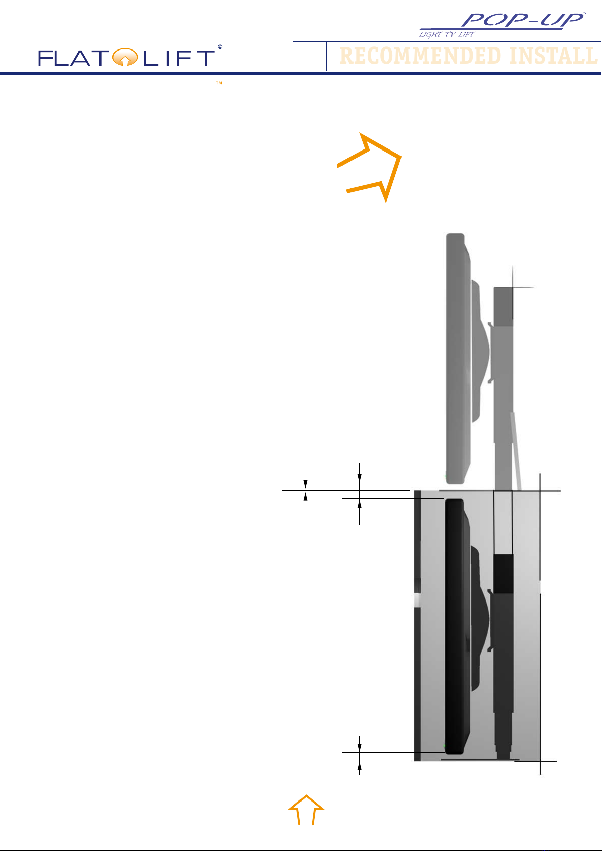
RECOMMENDED INSTALL
RECOMMENDED INSTALLATION
C.06:
Recommended installation
for integration with furnitu-
re:
The Flatlift Pop-Up Light has a
lift height of 635 mm. As dif-
ferent installation options are
possible for the system, we will
now explain how the system is
to be best arranged with instal-
lation on a cabinet.
The following rule applies
with cabinet and/or furnitu-
re installation:
There must be at least 10 mm
clearance underneath the TV
which is attached to the Flatlift.
This clearance is always requi-
red for the initialisation run.
Clearance of at least 10 mm
must also be provided above
the TV. When the Flatlift is fully
extended, we also recommend
a minimum clearance of 10 mm
between the bottom edge of the
TV set and the top surface of
the furniture.
The following calculation formu-
la therefore results with concern
to the height of the TV set:
min. 10
min. 10
min. 10
min. 12 - 19
Lift height, Flatlift = 635 mm - 3 x 10 mm min. clearance -
(12 to 19 mm) thickness of the cover, = 586 mm
586 mm = max. height of TV
If your TV is bigger of heavier,
we recommend you to change
over to the next Flatlift in the
range, the 30/42” or 43/50“ Flat-
lift Pop-Up Silver.
BUY NOW
P.013
Operating Manual
Outperform. Outlast.
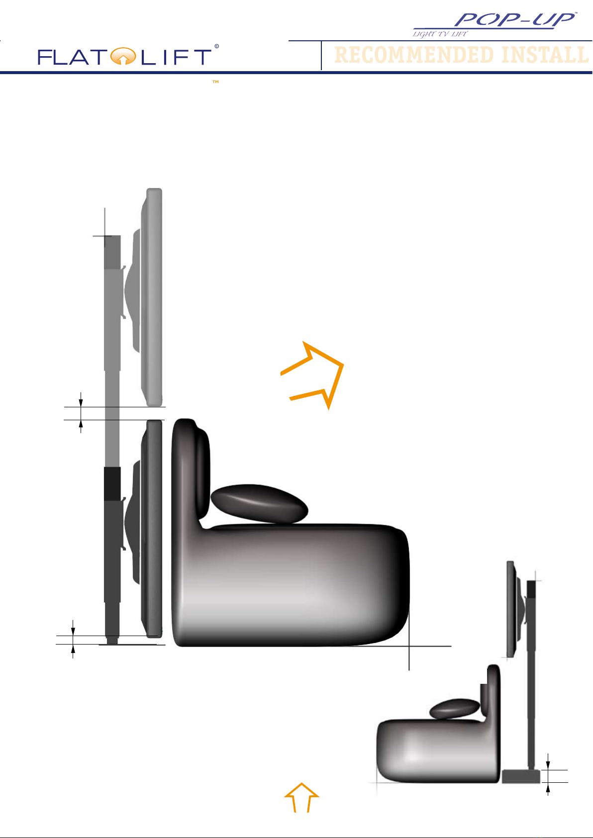
RECOMMENDED INSTALL
RECOMMENDED INSTALL
RECOMMENDED INSTALLATION
C.06:
Set up at
sofa or couch:
For installation behind a couch
or sofa, the following calculation
formula results:
With this TV set, the sofa must
not be higher than 610 mm.
The same thing applies to the
TV. If the TV height is less than
940 mm, then you can also
place the Flatlift on a platform
which is the same height as
the resulting height difference
to the upper edge of the sofa
(image 1).
If your TV is bigger of heavier,
we recommend you to change
over to the next Flatlift in the
range, the 30/42” or 43/50“
Flatlift Pop-Up Silver.
min. 10
min. 15
Height difference
Example:
Height of sofa = lift height of 635 mm - 10 mm min. clearance
from oor - 15 mm projection = 610 mm
610 mm = max. height of TV
Image 1
BUY NOW
P.014
Operating Manual
Outperform. Outlast.
Trouble shooting:
If your Flatlift is not working properly, please make sure you check the following things:
The Flatlift won’t move up or down
Is the power cord attached to the control box?
SCheck the mains connection
Are all of the plugs properly connected to the control box? (NOTE: plugs which are not connected properly
can damage the system)
SCheck all of the connections
SThe motor cables must be connected starting at port 1 and going up
Is there any evidence of damage to the cables, the control box, the remote control or the Flatlift?
S Damaged components must be exchanged. Please contact us. .
The Flatlift has stopped and will only move in the wrong direction.
SIs your Flatlift fully extended already?
SIs the TV too heavy?
SRemote control command possibly deleted!
SProgramming or initialisation error!
SStopping point incorrectly programmed
Have you, in error, attached a TV to your Flatlift which is too heavy?
STake the TV off the Flatlift and now see if the Flatlift works.
Is the IR remote control working?
SChange the battery in the remote control if necessary.
SMake sure, that the IR receiver is not hidden.
SCheck the cable connection of the IR receiver.
Please contact us if this particular point is relevant to you.
TROUBLE SHOOTING
TROUBLE SHOOTING
C.07:
If you experience any problems setting your system up or you experience an error, you can also contact
us over the telephone or via Email:
Customer Service:
Via email: info@atlift.de
Our telephone service time is 7.30 am - 5.30 pm. The telephone number is +49 (0) 62 41 - 97 20 10.
Please have the following information at hand / or include it in any email that you sent to us:
Your customer number
Your invoice number or delivery receipt number
The purchase date of your Flatlift
The name/model of your Flatlift system

P.015
Operating Manual
Outperform. Outlast.
TROUBLE SHOOTING
C.08:
Legal Notice
FLATLIFT TV Lift Systeme GmbH
Gewerbegebiet Südwest
Niedesheimer Str. 15
67547 Worms, GERMANY
Tel.: +49 (0) 62 41 97 20 10
Fax.: +49 (0) 62 41 97 20 12
info@atlift.de
www.atlift.de
Hours of business: Mon-Fri. 7:30 am- 5:30 pm
Managing Director: Sascha Rissel
HRA Mainz: HRB 40436
USt. (VAT) ID: On request
Status of document: JULY 2008
FLATLIFT References
© 2008 FLATLIFT TV LIFT SYSTEME GMBH
LEGAL NOTICE
LEGAL NOTICE
Table of contents
Other FLATLIFT TV Mount manuals


