manuals.online logo
Brands
  1. Home
  2. •
  3. Brands
  4. •
  5. Invision
  6. •
  7. TV Mount
  8. •
  9. Invision FX100 User manual

Invision FX100 User manual

English
www.InvisionTechnology.co.uk
Invision FX100
1 v20221025
Ergonomic Gas Assisted Monitor/
TV Wall Mount
Instruction Manual
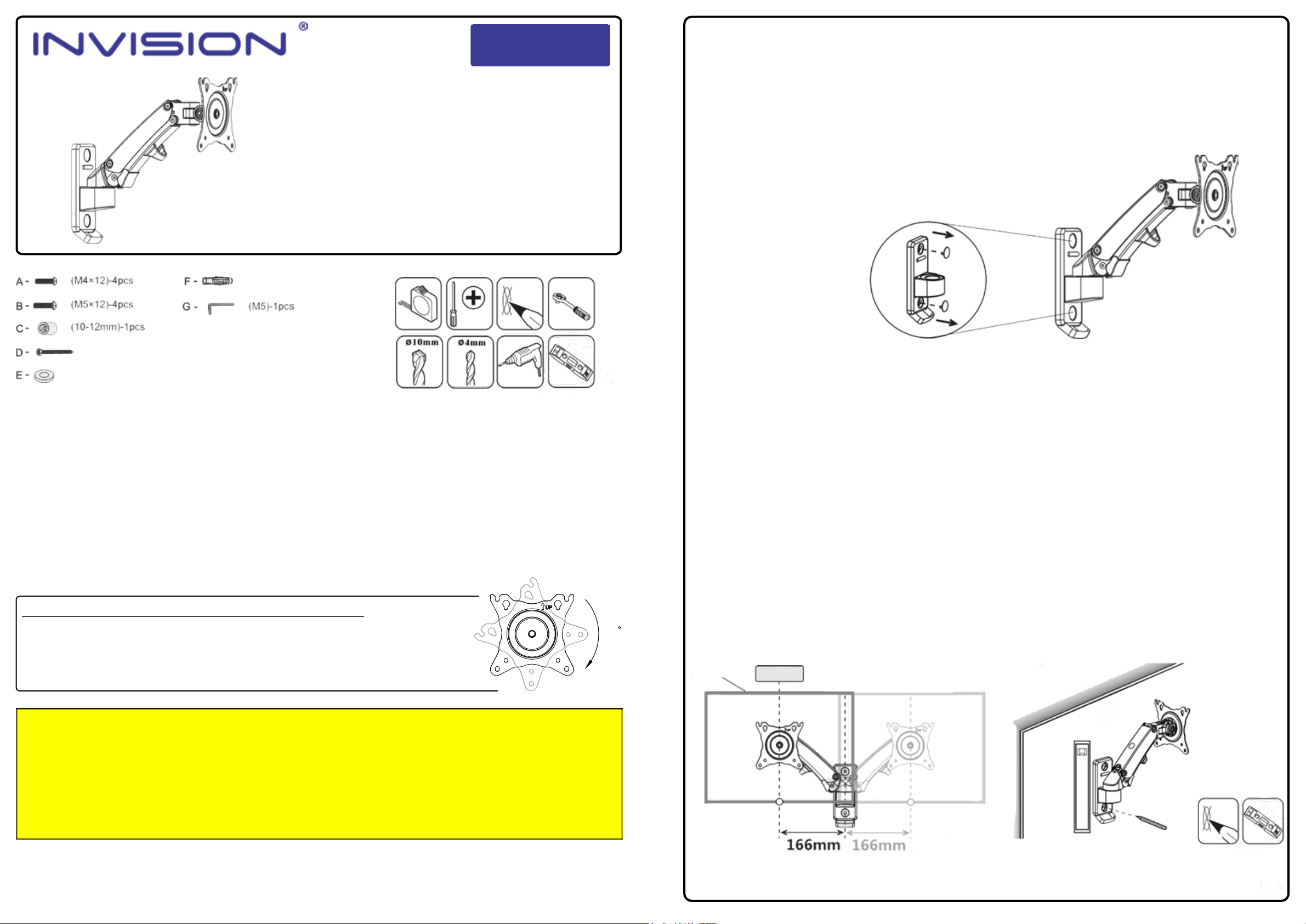
VESA Compliance 75x75mm & 100x100mm
Recommended Screen Sizes 17” - 27”
Integrated Cable Management
Load Capacity 2 - 7 kg (4.4 - 15.4lbs)
To receive large format PDF instructions please e-mail
help@InvisionTechnology.co.uk
Parts List:
(16x8.2x1.5)-2pcs
(10x60)-2pcs
(7x80)-2pcs
Tools List:
First things first: Check the box contains all the items in the parts list above.
Check VESA Compatibility: Please check the VESA measurements before drilling any holes (to check your
TV/Monitor VESA, measure distance between mounting holes on back of the TV/Monitor).
Check the weight of your TV/Monitor: You may need an extra person on hand to help!
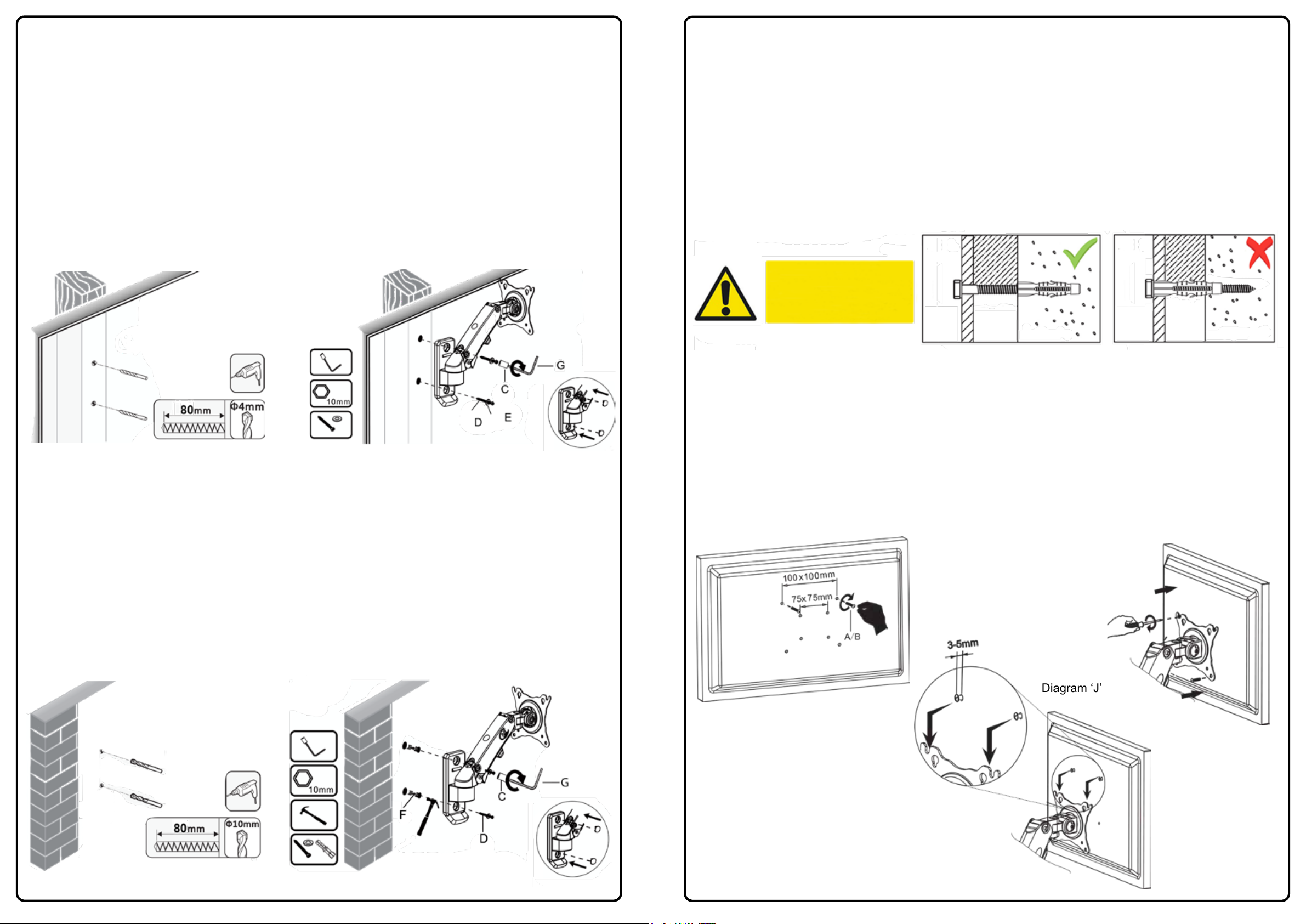
You will need a few additional tools: A drill and 10mm masonry drill bit or 4mm wood drill bit, depending on
the fixing surface, a large Phillips screwdriver, a pencil, a spirit level and a 12mm socket and ratchet
(a 12mm socket can be used with the Allen key which are supplied – Parts C & G).
Please wear safety glasses before using your drill – if in any doubt, consult your retailer or an experienced
installer.
Now please read the instructions fully and plan how to install your wall mount!
45
UNBOXING - PLEASE NOTE: NOT FAULTY OR BROKEN
This product is packed with the faceplate at a 45° angle to fit smaller packaging and reduce environmental waste.
Please rotate the faceplate 45° clockwise before mounting your monitor.
PLEASE NOTE: Faceplate rotation has high resistance by design and may need a little force to move. This is
normal and ensures that your screen will be held steady for many years to come without any unwanted
movement.
WARNING!
Severe personal injury and property damage can result from improper installation or assembly. Please read the following warning carefully before beginning.
• If you do not understand the instructions or have any concerns or questions please contact us or a competent installer.
• Do not install or assemble if the product or hardware is damaged or missing. If you require replacement parts, please contact us at Invision for assistance.
• This product fits most VESA compliant 17”- 27” TV/monitors to a maximum weight of 7kg (15.4lb).
• This product has been designed for use on vertical walls constructed of wood studs (minimum 2” x 4”/ 51mm x 102mm) or masonry (solid concrete 2000 PSI density minimum).
• For safe installation, the wall you are mounting must support minimum 3 times the weight of the total load (the TV bracket, the TV and all accessories).
• Do not use this product for any other application than the original design purpose.
• This product contains moving parts, please use with caution.
• When installing flat panel display, take care not to damage electrical wiring or power source.
• The manufacturer will bear no responsibility for mounting to the vertical wall, or incidental or consequential damages arising there from.
• The manufacturer disclaims any liability for the modifications, improper installation or installation over the specified weight range.
• The manufacturer will not be liable for any damages arising from the use of, or inability to use the product.
• This product contains a high pressure gas spring. This mechanism is not user serviceable and any interference could result in injury or damage. Please dispose of with caution.
• In order to ensure the performance of the gas spring it is recommended to fully extend the arm several times per month.
Lets Get Started!
If you require assistance please contact us at: help@InvisionTechnology.co.uk
2
Step 1 - Preparing your Wall Mount
1. Open the box and take out the wall mount. Remove 2x wall plate cover caps as shown in Diagram ‘A’ and
put them to one side.
(Important: DO NOT attempt to adjust the tension of the wall mount before mounting on the wall).
Tip: Use one of the fixing
screws and push through
the hole on the back of the
wall plate to release the
cover caps
Diagram ‘A’
Step 2 - Positioning and Marking Out
1. Before marking out note the centre line of the TV will be 166mm offset to the wall fixing centre line when
the wall mount is pushed back to the wall - see diagram ‘B’.
Also take into consideration the length of cables you are using with your equipment leaving an
adequate amount of slack so the wall mount can function properly.
2. Position the mount on the wall using the wall fixing plate as a template and mark out the 2 holes using a
spirit level and pencil. (Ensure your markings are clearly marked level both horizontally and vertically on the
wall) - see diagram ‘C’
Centre
Display
Diagram ‘B’ Diagram ‘C’
3
Step 3 - Securing Wall Mount to your Wall
This wall mount is designed to be attached to either fixed wooden studs within traditional plasterboard
(drywall) walls or into solid masonry (brick or concrete) walls.
Step 3a - Wood Stud Installation
1. For mounting to wooden studs – carefully locate the wooden stud and mark the position of the holes level
vertically and drill into the wood using a 4mm drill to a depth of 80mm - see diagram ‘D’.
2. Hold your wall mount in position and insert the supplied screws and washers, check the wall mount is level
and fully tighten into the wood using a 12mm socket set or parts ‘C/G’ socket and Allen key (plastic plugs are
not required when fixing into wood) - see diagram ‘E’. Replace wall plate cover caps once the wall mount is
secure.
Diagram ‘D’ Diagram ‘E’
Step 3b - Masonry Installation (Brick & Concrete)
1. For mounting to masonry walls, please mark the wall carefully and drill using a 10mm masonry drill bit to
full depth of 80mm minimum ensuring the holes drilled are free from debris - see Step 3c diagram ‘H’.
2. Fully insert the plastic plugs ‘F’ into the solid wall (pushed beyond any plaster) closely following diagram
‘F’. Please ensure they fit securely and are not visible in the holes.
3. Insert screws ‘D’ and fully tighten into the plastic plugs using a ratchet and 12mm socket set or parts ‘C/G’
socket and Allen key until secure - see diagram ‘G’.
Diagram ‘F’ Diagram ‘G’
4
Step 3c - Please Note
Many modern houses have an air-gap behind plasterboard or drywall. Our fixings are only designed to work
with the plastic plug fully inserted into the masonry that lies behind any plaster or drywall air gap. To use our
fixings in this way YOU MUST inserted into the plug past any plaster/drywall and fully into the underlying
masonry to gain a secure fixing. (The drill depth may have to be increased to make sure the plug can be fully
inserted to the masonry).
When fitting, the screw must be at least 3/4 of the way into the plug, and the plug must be fully inserted into
the masonry to be effective - see diagram ‘H’.
Depending on the plasterboard/dry wall air gap you may need to purchase longer fixings to ensure a secure
fix (plasterboard wall fixings are NOT supplied).
Diagram ‘H’
WARNING
Please see diagram right
for correct installation of
screws & plugs Plaster
board/
drywall
Dot dab/
Air gap Solid wall
Plaster
board/
drywall
Dot dab/
Air gap Solid wall
Step 4 - Mounting your Monitor/TV
1. Check TV/monitor VESA by measuring the distance between the mounting holes on the back of the
screen - this is where bolts A/B will fit.
2. Screw 2 bolts into the top two holes on the back of the TV/monitor using bolts A or B and tighten in 3 turns
leaving 5mm of room between the bolt head and rear of screen for hanging - see diagram ‘I’.
3. Carefully lift TV/monitor and hang onto the VESA plate - see diagram ‘J’.
4. Fit the bottom 2 bolts into the VESA plate and tighten all the bolts - see diagram ‘K’.
Please Note: Set the torque of arm if screen moves down too easily (see Step 5)
Diagram ‘I’
Diagram ‘J’
Diagram ‘K’
5
Step 5 - Using Your Invision FX100 Wall Mount
Setting the tension of the wall mount to balance the weight of the TV/monitor
Once fitted the screen may rise or lower depending on the TV/monitors weight. From minimum
tension to maximum tension there are 19x full rotations. When making adjustments make one full turn
of the Allen key and check by depressing the upper arm to see if the TV/monitor is balanced evenly.
1. If the screen moves upwards of its own accord then adjust the tension using the 5mm Allen key ‘G’ and
wind the set screw in the minus direction (clockwise) - see diagram ‘L’.
2. If the screen moves downwards of its own accord then adjust the tension using the 5mm Allen key ‘G’ and
wind the set screw in the plus direction (anti-clockwise).
Continue to make adjustments until the TV/monitor weight feels equal to the tension of the wall mount.
It should hold in place when positioning the TV/monitor and not raise or lower of its own accord.
Diagram ‘L’
Step 6 - Cable Management
Please leave adequate slack while routing cables
1. Remove the upper cable management clip by removing the screw - see diagram ‘M’.
2. Route all cables up through the base cable management clip.
3. Feed the cables into the upper cable management clip and re-attach the screw.
Diagram ‘M’ 1.
2.
3.
6
Step 7 - Adjusting the Tilt Angle
The tilt can be set to your desired viewing angle by simply moving the screen backwards and forwards by
hand. If you find the screen moves forward of its own accord, the tilt adjustment can be tightened using
Allen key ‘G’ - see diagram ‘N’.
Diagram ‘N’
Step 8 - Rotational Features
Your monitor arm allows you to rotate your screen through 360 degrees to view in portrait mode or landscape
mode providing the VESA mount on your screen is central.
Please Note:
Beware of trapping or breaking cables when rotating TV/Monitor. DO NOT ROTATE MORE THAN 90
DEGREES IN EACH MOTION
Diagram ‘O’
Troubleshooting:
Don’t panic! In case of any issues with compatibility or for any advice on fitting, please contact our team at
help@InvisionTechnology.co.uk and we will help you overcome any problems. All our products carry our
Compatibility Promise.
Your installation is now complete - Sit back & enjoy!
To activate your 3 year warranty please email your name and
product ref FX100 to warranty@InvisionTechnology.com.uk

Other Invision TV Mount manuals

Invision ScreenStation GT1200 User manual

Invision

Invision ScreenStation GT1200 User manual

Invision MX200 User manual

Invision

Invision MX200 User manual

Invision HDTV-M User manual

Invision

Invision HDTV-M User manual

Popular TV Mount manuals by other brands

AVF 1040700 Leaflet

AVF

AVF 1040700 Leaflet

ERARD FITUP L 035300 manual

ERARD

ERARD FITUP L 035300 manual

Echogear EGAV-RTVSS1 instruction manual

Echogear

Echogear EGAV-RTVSS1 instruction manual

Speaka Professional SuperFlex 629565 operating instructions

Speaka Professional

Speaka Professional SuperFlex 629565 operating instructions

Kanto M200 user manual

Kanto

Kanto M200 user manual

Kimex 013-2053 Installation instruction

Kimex

Kimex 013-2053 Installation instruction

Vivo STAND-V032T instruction manual

Vivo

Vivo STAND-V032T instruction manual

Behringer POWERPLAY 16 P16-MB quick start guide

Behringer

Behringer POWERPLAY 16 P16-MB quick start guide

Kogan KAWLMCRVLA user guide

Kogan

Kogan KAWLMCRVLA user guide

Bell'O 7610 instruction manual

Bell'O

Bell'O 7610 instruction manual

Dynex DX-TVM102 user manual

Dynex

Dynex DX-TVM102 user manual

KSL UKR2EN228 quick start guide

KSL

KSL UKR2EN228 quick start guide

AVF CNL665K-F manual

AVF

AVF CNL665K-F manual

Technibel K 60 U 026 Z installation instructions

Technibel

Technibel K 60 U 026 Z installation instructions

Reer 73010 Instructions for use

Reer

Reer 73010 Instructions for use

LDI Spaces SAFCO Impromptu 8926 Assembly instructions

LDI Spaces

LDI Spaces SAFCO Impromptu 8926 Assembly instructions

Gembird WM-37T-01 user manual

Gembird

Gembird WM-37T-01 user manual

Gembird WM-55F-03 user manual

Gembird

Gembird WM-55F-03 user manual

manuals.online logo
manuals.online logoBrands
  • About & Mission
  • Contact us
  • Privacy Policy
  • Terms and Conditions

Copyright 2025 Manuals.Online. All Rights Reserved.