Bauhn ACTVB-0721 User manual

Installation Guide
MODEL: ACTVB-0721
Corner TV
Wall Mount
MODEL: ACTVB-0721 PRODUCT CODE: 704085 07/2021
AUS
AFTER SALES SUPPORT
1300 002 534

2
Welcome
Congratulations on your purchase!
This installation guide tells you all you need to know about using your new BAUHN®product.
Please take special note of any important safety and usage information presented with the symbol.
All products brought to you by BAUHN®are manufactured to the highest standards of performance and safety and,
as part of our philosophy of customer service and satisfaction, are backed by our comprehensive 1 Year Warranty.
Domestic use only: This product is intended for indoor domestic use only. It is not suitable for commercial, industrial
or outdoor use. Do not use this product for anything other that its intended purpose, and only use it as described in
this guide.
We hope you will enjoy using your purchase for many years to come.
Fixing a TV to a wall mount requires specialist knowledge. We assume no liability for any injury or
material damage incurred due to incorrect assembly or use. Make sure to follow all instructions and if
you require professional advice, please consult a relevant tradesperson.
WARNING
This wall mount is for indoor home use only.
NOTE

3
Specications 19
Compliance and
Responsible Disposal 20
Warranty Information 21
Contents
Welcome 2
Unpack and Prepare 4
What's in the box 4
Parts List 5
Product Overview 5
Installation Pack (Assembly Hardware) 6
Installation 7
Corner Installation for a Brick or Concrete Wall 8
Corner Installation for a Wood Stud Wall 10
Flat Wall Installation for a Brick or Concrete Wall 12
Flat Wall Installation for a Wood Stud Wall 14
Attaching the Wall Mount to the TV 16
Securing the TV 17
Adjusting the Viewing Angle 18
Repair and Refurbished
Goods or Parts Notice 22

4 | UNPACK AND PREPARE
Before setting up your new product,
check you have everything:
Unpack and Prepare
What's in the box
A. Corner TV Wall Mount
B. Installation Pack (see page 6 for information)
C. Installation Guide
D. Warranty Certificate
E. General Safety Warnings
A
B
C D E

PARTS LIST| 5
Parts List
Product Overview
Wall Base Plates TV Mounting Plate
Spirit Level
Right Monitor Bracket
Lock Nuts
Left Monitor Bracket

6 | PARTS LIST
Installation Pack (Assembly Hardware)
The illustration below shows the contents of the installation pack. These are the parts that
you will need to assemble this wall mount. Some parts are not shown at the same scale.
(G)
Self-Tapping Screw
ST8 x 50mm
(8pcs)
(H)
Masonry Plug
10 x 50mm
(8pcs)
(I)
Flat Washer
M5-M6-M8
(4pcs)
(K)
Plastic Spacer
D8 x 5mm
(8pcs)
(J)
Washer
ø 18 x ø 8.5 x 1.5mm
(8pcs)
(A)
Bolt
M5 x 16mm
(4pcs)
(B)
Bolt
M5 x 25mm
(4pcs)
(C)
Bolt
M6 x 16mm
(4pcs)
(D)
Bolt
M6 x 25mm
(4pcs)
(E)
Bolt
M8 x 16mm
(4pcs)
(F)
Bolt
M8 x 25mm
(4pcs)
A B C D E F G H I J K

INSTALLATION | 7
Installation
Make sure you read and understand all instructions. Handle and use all materials strictly according to the
instructions. If you do not understand these directions, or have any questions in relation to the safety of the
installation,werecommendyoucontactaqualiedprofessional.
Note: This wall mount is for indoor home use only.
Installation steps:
1Preparation
2Drilling the holes
3Attaching to the wall
4Attaching the wall mount to the TV
5Securing the TV
6Adjusting the Viewing Angle
TIP: Installation of the Wall Mount will be easier with two people.
WARNING: Be sure to choose a structurally sound wall area that is strong enough to hold the weight of the TV as
well as the wall mount. Mount the wall plate far away from any water source and direct sunlight.
WARNING: DO NOT attach the wall mount to a hollow wall or decorative cardboard.
Tools Required: To complete the following steps you will need:
A. Pencil
B. Phillips head Screwdriver
C. Power Drill
D. Hammer
E. Stud Detector
F. Adjustable Wrench
A
DE F
BC

8 | INSTALLATION
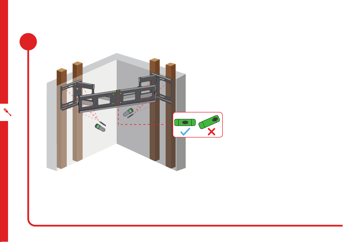
Using the wall base plates as a template, mark eight holes in the locations as shown above.
The distance (d) from the corner to each wall base plate can be freely adjusted if required.
NOTE:Ensurethatyoualignthewallmountsothatthespiritlevelisatandeven.
Preparation
Corner Installation for Brick or Concrete Wall
[d] [d]
1A

INSTALLATION | 9
On the marked holes, pre-drill holes of
10mm diameter and 60mm depth into the
concrete or brick wall. Then wedge the
masonry plugs (H) into the holes, gently
tap each plug with a hammer until they are
ushwiththewallasillustratedontheleft.
WARNING: Do not drill into mortar joints.
Please pay attention to the electrical lines
and also the location of gas and water
lines when drilling holes.
Attaching to the Wall
Drilling the Holes
Hold the wall plates against the wall and align the holes in
the plate to the holes drilled into the wall.
Screw the wall plates to the wall with the self-tapping
screws (G): insert them through the washers (J) into each
masonry plug (H) in the wall and then tighten the screws.
2A
3A
(J)
(G)
[H]
10 | INSTALLATION
NOTE: If you are installing the wall mount to a wood stud wall,
consult a builder for advice. The wall must be strong enough for
the weight of the wall mount and the TV.
WARNING: You must spread the
wall plate across two studs.
Use a stud detector to locate the centre of the framing studs.
Mark eight holes in the locations as shown above. Use the wall base plates as a template.
1B Preparation
Corner Installation for a Wood Stud Wall
Table of contents
Other Bauhn TV Mount manuals

Bauhn
Bauhn ASWM65-0921 User manual

Bauhn
Bauhn ALPB80-0421 User manual

Bauhn
Bauhn ALPB80-0319 User manual

Bauhn
Bauhn AWMW1-315 User manual

Bauhn
Bauhn AMAB-0621-D User manual

Bauhn
Bauhn ASWM65-0920 User manual

Bauhn
Bauhn ASWM65-0519 User manual

Bauhn
Bauhn ASWM65-0320 User manual

Bauhn
Bauhn AWBS-0818-W User manual

Bauhn
Bauhn ACTVB-1120 User manual

Bauhn
Bauhn AMAB-0621-S User manual

Bauhn
Bauhn ASWM65-0919 User manual

Bauhn
Bauhn ALPB80-0718 User manual

Bauhn
Bauhn AMAB-0222-D User manual

Bauhn
Bauhn ASWM65-0922 User manual

Bauhn
Bauhn AMAB-0620-S User manual

Bauhn
Bauhn ALPB80-0719 User manual

Bauhn
Bauhn ALPB80-1021 User manual

Bauhn
Bauhn ALPB80-1020 User manual

Bauhn
Bauhn AMAB-0620-D User manual


