Flatworks plyfly User manual

For Ages 12+
PlyFly Go‑Kart Instruction Guide • 2015 Release
HOW TO BUILD
YOUR
PLYFLY GO-KART!

150718 PLYFLY rev A_Cover |August7,20155:06PM
II
Thank you for supporting
the FLATWORKS Kickstarter campaign.
Your contribution is a great help, and your
support is much appreciated.
We hope you’re as excited to get
started on your new adventure as we are to
be working on the FLATWORKS.
Enjoy your new Plyfly Go‑Kart!
Check back soon and see what else we make!
Thank you
the Flatworks Crew,
&

150718 PLYFLY rev A_Cover |August7,20155:06PM
III
Steven Hynes
Cam McCulloch
Alan Miyasaki
Stephan Schnitker
Chris Patton
Joe Barton
Liam Newman
No Regrets
Ray Colwell
Henry E.
Carl Moulton
Mark ChengIan
Drummond
CJBCN
James “Udub” Underwood
Jesse Cannone
Luke
Jim Mahoney
Tim Baker
Karl Eberhardt
Tomas Petru
David Moore
David Geisinger
Ken Short
Andrew B. Bartels
Brian Kaleida
Matthew & Keri
Zee
Jim
K Brotman
Dennis Cox
Chris DePerro
Family Woo
Marcus Leef
Tyra Hammett
Nathan Pelsor
Douglas Dayton
Sam Bowling
Lindsey Zimmerman
Anthony
Joshua Marcus
Joe W.
Greg Brncick
Grandpa Rex
Alex Gomes
Lindsay Lauber
Joseph Asti
Nick Vines
Herk
Brian Jepson
Steve Baker
Louis Tovar
Mark Tracy
Anonymous
Michael Lindahl
JouleLee
Tiegen
Mohit
Sam Bell
Emily H.
Andrew Marc
Tim Owens
Chris Porter
Matthew Clark
Ryan Bradley
Michael Lindahl
Adam “Hock” Hocherman
Michael McGrath
Dave Krugman
Daniel Cianci
Scott Newman
Russ Kadooka
Mitch
Bob

1 5 0 7 1 8 P LY F LY r e v A _ T O C |August7,20155:06PM
IV
What's Inside?
1 Exploring the kit 1
Warnings and safety 2
Handling and storage 2
Why Wood? 3
Good to know 3
What’s in the kit? 3
Unpacking the boxes 4
2 Getting Started 6
Getting started 7
Recommended tools 7
Chisel & hammer method 7
Reciprocating saw method 7
3 Seat Assembly 8
Plywood sheet reference 9
Recommended tools 9
Required hardware 9
Required wooden parts 10
Assembling the seat 11
4 Steering Column Assembly 12
Plywood sheet reference 13
Recommended tools 13
Required hardware 13
Required wooden parts 13
Assembling the steering shaft 14
5 Steering Rack Assembly 15
Plywood sheet reference 16
Recommended tools 16
Required hardware 16
Required wooden parts 17
Assembling the steering rack 17
6 Fixed Steering Column Assembly 18
Plywood sheet reference 19
Recommended tools 19
Required hardware 19
Required wooden parts 20
Assembling the steering column 20
7 Steering Spindle Assemblies 21
Plywood sheet reference 22
Recommended tools 22
Required hardware 22
Required wooden parts 23
Assembling the left & right steering spindles 24
8 Pedal Assemblies 25
Plywood sheet reference 26
Recommended tools 26
Required hardware 26
Required wooden parts 27
Assembling the gas & the brake pedals 27
9 Frame Assembly 28
Plywood sheet reference 29
Recommended tools 30
Required hardware 30
Required assemblies 30
Required wooden parts 31
Assembling the frame 32
10 Putting the go‑kart together 37
Overview of the recommended tools 38
Overview of the required hardware 38
Overview of the required but not provided 41
Overview of the required wooden parts 41
Overview of the required assemblies 41
Part 1 Install the rear axle 43
Part 2 Install the brake caliper 44
Part 3 Install the steering column assembly 45
Part 4 Install the steering spindles 46
Part 5 Install the gas & brake pedals 47
Part 6 Install the gas & brake cables 49
Part 7 Install the engine and drive train 52
Part 8 Install the wheel assemblies 57
Part 9 Install the seat assembly 58
Part 10 Install the fairings 59
11 Master List 60
Visual reference of the plywood sheets 61
List of the wooden parts 62
List of the wooden assemblies 66
List of the tools needed 67
List of loose contents 68
List of the packaged contents 70
12 Legal 72
Legal 73
13 Terms & Conditions 74
Terms & Conditions of Purchase and Use 75

1 5 0 7 1 8 P LY F LY r e v A _ C H 1 |August7,20155:08PM
Introduction
Each Plyy Go-Kart kit arrives in 3 boxes.
Review the contents of each box to ensure you have all the
necessary parts to begin building your next adventure!
1
1 Exploring the kit

1 5 0 7 1 8 P LY F LY r e v A _ C H 1 |August7,20155:08PM
Warnings and safety
Riding karts can be dangerous.
Please use caution and prudence and follow the
guidelines below.
• Avoid operating your kart in crowded or conned areas.
• Any children that use the kart are of an appropriate
age and do so under proper supervision.
The recommended age for this kart is 12+.
• Avoid using your kart near any other vehicular trac or
on public roads.
• Never try to t more than one person in the kart.
• Always wear a DOT‑rated helmet and gloves while
operating the kart.
• Never aim the kart at other people, objects or animals.
• Prior to riding, every rider should familiarize
themselves with:
‒Their environment
‒Any obstacles or dangers.
‒The location and function of the
emergency shuto switch.
• Inspect the kart prior to each run to make sure that each
element is properly functioning. Test:
‒Brakes lock the rear wheel.
‒Shut o switch kills engine.
‒Clutch, chain, sprocket and sprocket guard are
properly tightened and functioning.
‒The wheels are all on and tightened.
‒The steering system is functioning properly.
‒There are no areas of brake discs, wheels, chain or
other moving elements rubbing on the wood.
‒That all shaft keys (clutch, sprocket, brake disc, wheels)
are installed and secured in place by a tight set screw.
‒Ensure all fasteners are tight and properly torqued.
‒The safety ag is installed.
‒The seat is properly installed and adjusted.
• Do not attempt to leave the ground with the kart.
It is not designed or intended for jumping.
• Ensure the rider has no articles of loose clothing
or hair that could get caught in the spinning
mechanisms of the kart.
Handling and storage
• The kart is heavy.
• Use at least two people to lift or move it.
• Some surfaces may be hot after use, handle with
caution. These may be from friction in bearings and
brakes or from the engine.
• If gasoline is spilled on the wood, leave the kart
outside in a well ventilated area to dry before use
or storage. Be very careful about exposure to potential
ignition sources until it dries.
• Do not tip the kart. Fuel may spill from the carburetor if
inclined too much. If you need to stand up the kart, start
the engine and turn o the fuel valve. Let the engine run the
carburetor dry.
• Store the kart in a dry, clean area and coat the wood with
a paint or coating for the longest life.
21 Exploring the kit

1 5 0 7 1 8 P LY F LY r e v A _ C H 1 |August7,20155:08PM
Why Wood?
Sure, steel karts are fun and strong, but they require a large
number of specialized tools to build, repair or modify. Tools
that most people don’t have. Wood, on the other hand, can
be crafted with tools available in most homes and all home
improvement stores. We want to provide kits that people
can make their very own, by painting, xing or modifying and
wood is a natural t for this.
The wood used in this kit is a 3/4 inch Baltic Birch plywood.
It is a natural t for the go-kart due to it’s strength and
appearance. The 13 plies make it incredibly strong and
give the end grain a beautiful contrast. Best of all, it can be
modied, repaired or reworked with common household
tools.
Good to know
It is vitally important that anyone riding a go‑kart wear the
proper protective gear. The rider should wear, at a minimum,
a full‑face DOT‑rated engine cycle helmet, gloves and a
helmet supporting neck brace. These items and other safety
equipment are not supplied with the kits but can be found
through many online or retail sellers.
We aim to provide the best assembly documentation in
the industry and will include written instructions and online
videos for all of the crucial steps. We will be available to
help you through the process, so if you need assistance,
please ask. However, this is a kit and the ultimate
build quality is up to you.
What’s in the kit?
Each Plyy Go-Kart kit arrives in 3 boxes. Box 1 is a at box
with the wooden structural parts. Box 2 is the engine and
box 3 is the hardware.
1.2.3. That’s it!
Packaging reference
Description Reference
Box 1 – wood
Dimension: 30” x 60” x 3”
Box 2 –engine
Dimension: 14” x 14” x 16”
Box 3 – hardware & wheels
Dimensions: 24” x 12” x 12”
For more the complete list of hardware, see Visual reference of the plywood sheets, on page 61.
3
PlyFly Go‑Kart Instruction Guide • 2015 Release

1 5 0 7 1 8 P LY F LY r e v A _ C H 1 |August7,20155:08PM
Unpacking the boxes
Each box should have the following components.
Box 1 contents
2.5 HP 4.0 HP 4.0 HP 4.0 HP 4.0 HP
№DESCRIPTION SINGLE WHEEL
10” WHEELS
SINGLE WHEEL
10” WHEELS
SINGLE WHEEL
12” WHEELS
LIVE AXLE
10” WHEELS
LIVE AXLE
12” WHEELS
3Plywood Sheet
3/4” depth •••••
1
Plywood Sheet
1/4” depth •••••
1Flag •••••
1Drive Shaft
Steel, Keyed, 5/8” D 18” L 18” L 18” L 33” L 36” L
Box 2 contents
2.5 HP 4.0 HP 4.0 HP 4.0 HP 4.0 HP
№DESCRIPTION SINGLE WHEEL
10” WHEELS
SINGLE WHEEL
10” WHEELS
SINGLE WHEEL
12” WHEELS
LIVE AXLE
10” WHEELS
LIVE AXLE
12” WHEELS
1Gas Powered Engine
2.5 HP MODEL •――――
1Gas Powered Engine
4.0 HP MODEL ―••••
41 Exploring the kit

1 5 0 7 1 8 P LY F LY r e v A _ C H 1 |August7,20155:08PM
Box 3 Contents
2.5 HP 4.0 HP 4.0 HP 4.0 HP 4.0 HP
SINGLE WHEEL
10” WHEELS
SINGLE WHEEL
10” WHEELS
SINGLE WHEEL
12” WHEELS
LIVE AXLE
10” WHEELS
LIVE AXLE
12” WHEELS
DESCRIPTION
Plyy Packaged Hardware Kit Sealed kit of go‑kart hardware 1 1 1 1 1
Clutch #35 Chain, 11 Tooth Pulley for 5/8” shaft 2.5 HP Model 1― ― ― ―
Clutch #35 Chain, 12 Tooth Pulley for 3/4” shaft 4.0 HP Model ―1 1 1 1
Clutch Guard Side Engine Mounting Plate 1 1 1 1 1
Clutch Guard Top Top C over 1 1 1 1 1
Clutch Guard Cover Outside Cover 1 1 1 1 1
Sprocket 60 Tooth, #35 Chain, 5/8” D bore 1 1 1 1 1
Roller Chain #35 Chain, 29‑5/8” L 1 1 1 1 1
Chain Link For connecting #35 Roller Chain 1 1 1 1 1
Control Cable 1/16” D, throttle & brake control cable 2 2 2 2 2
Red Throttle Cable Brake conduit, 5’ L 1 1 1 1 1
Green Throttle Cable Gas conduit, 6’ L 1 1 1 1 1
VXB Mounted Bearing 5/8” ID 3 3 3 3 3
Brake Caliper 1 1 1 1 1
Brake Disc 1 1 1 1 1
Brake Hub 1 1 1 1 1
Long Hex Bolt Grade 5, 5/8”‑11, 11” L Single Wheel Kit Only 1 1 1 ― ―
Short Hex Bolt Grade 5, 5/8”‑11, 6.5” L 4 4 4 4 4
Precision Rod 1/4” D, 18” L 1 1 1 1 1
Drawer Slide Hardware included, 10” L 1 1 1 1 1
Green Elastic Cord 3/16” OD, 18” 1 1 1 1 1
Spax Screw 1 Box,#8 1‑1/2” L 1 1 1 1 1
10” D Wheels Rear driven wheel 1 1 ―2―
10” D Wheels Undriven wheel 3 3 ―2―
12” D Wheels Rear driven wheel ― ― 1―2
12” D Wheels Undriven wheel ― ― 3―2
PlyFly Flag 1 1 1 1 1
For more the complete list of hardware, see List of the packaged contents, on page 70.
5
PlyFly Go‑Kart Instruction Guide • 2015 Release

1 5 0 7 1 8 P LY F LY r e v A _ C H 2 |August7,20155:08PM
Introduction
Preparing for a Plyy Go-Kart build, you will need to cut out
each structural wooden part from the plywood sheets.
The more time spent trimming tabs cleanly will save
a lot of sanding time.
6
2 Getting Started

1 5 0 7 1 8 P LY F LY r e v A _ C H 2 |August7,20155:08PM
Getting started
INSTRUCTIONS
1. Open the provided boxes to ensure all the parts are
included.
2. To release the structural wooden parts from the
plywood sheets, use the recommended tools and follow
one of the suggested methods:
‒A chisel and hammer method
‒The reciprocating saw method
Recommended tools
DESCRIPTION REFERENCE
Chisel
Hammer
Orbital sander
Sandpaper
Jigsaw or
Reciprocating saw
(optional)
Chisel & hammer method
INSTRUCTIONS
1. To free a part from the plywood sheet, place the at side
of chisel against the keeper side of the part.
2. Strike the top of the chisel sharply with a hammer to
remove wood from the notches.
3. Repeat this procedure until all the parts are free.
4. To nish the edges of all the wood parts that become
spalled or rough from the cutting process using an orbital
sander, or sheet of sandpaper.
Reciprocating saw method
INSTRUCTIONS
1. Select the correct blade for the cutting wood
2. Place the plywood sheet on saw horses or a workbench,
or clamp it in a vice, depending on which is best suited for
your purpose.
Note Make sure you have sucient light to see your cutting
marks easily
3. To free a part from the plywood sheet, position the blade
close to the edge of the wood tab (where you will begin
your cut)
Note Complete the cut by continuing through the material,
being careful to support any piece that may drop when the cut is
nished until the blade is free of it.
4. Repeat this procedure until all the parts are free.
5. To nish the edges of all the wood parts that become
spalled or rough from the cutting process using an orbital
sander, or sheet of sandpaper.
For more information on What’s in the kit?, see page 3.
7
PlyFly Go‑Kart Instruction Guide • 2015 Release

1 5 0 7 1 8 P LY F LY r e v A _ S e a t |August7,20155:06PM
Introduction
Before beginning this assembly, be sure to chisel out and sand
parts 22 ‑ 33. These 12 components are required to fully assemble
the go‑kart seat
8
3 Assembly
3 Seat Assembly

1 5 0 7 1 8 P LY F LY r e v A _ S e a t |August7,20155:06PM
Plywood sheet reference
DESCRIPTION REFERENCE
Sheet 1
3/4” Plywood Sheet ‒Parts 24
24
Sheet 3
3/4” Plywood Sheet
‒Parts 22‑23
‒Parts 25‑27
22
23
252726
Sheet 4
1/4” Plywood Sheet ‒Parts 28‑31
31
302829
Recommended tools
DESCRIPTION REFERENCE
Dead blow hammer
or mallet
Electric driver
Required hardware
№DESCRIPTION REFERENCE
32
Spax Screw
#8, 1‑1/2” L
P N 12519
9
PlyFly Go‑Kart Instruction Guide • 2015 Release

1 5 0 7 1 8 P LY F LY r e v A _ S e a t |August7,20155:06PM
Required wooden parts
DESCRIPTION REFERENCE
Part 22
Seat Side Left
PLYWOOD SHEET 3
Part 23
Seat Side Right
‒Gas tank side
PLYWOOD SHEET 3
Part 24
Seat Crossbar
PLYWOOD SHEET 1
Part 25
Seat Crossbar
PLYWOOD SHEET 3
Part 26
Seat Crossbar
PLYWOOD SHEET 3
Part 27
Seat Crossbar Bracket
PLYWOOD SHEET 3
DESCRIPTION REFERENCE
Part 28
Seat Bolster Left
PLYWOOD SHEET 4
Part 29
Seat Bolster Right
PLYWOOD SHEET 4
Part 30
Seat Thigh Bolster Left
PLYWOOD SHEET 4
Part 31
Seat Thigh Bolster Right
PLYWOOD SHEET 4
Part 32
Seat Back
PLYWOOD SHEET 4
Part 33
Seat Bottom
PLYWOOD SHEET 4
Note If you received a 1/4” plywood sheet that is nished on one side and
you intend to paint the Plyy go-kart seat; reverse the wooden parts 28-33
(so the unnished side is outward facing and
ready to receive paint).
10 3 Seat Assembly

1 5 0 7 1 8 P LY F LY r e v A _ S e a t |August7,20155:06PM
Note If you received a 1/4” plywood sheet that is nished on one side and
you intend to paint the Plyy go-kart seat; reverse the wooden parts 28-33
(so the unnished side is outward facing and
ready to receive paint).
Assembling the seat
INSTRUCTIONS
1. Align parts 22 & 23 with the slots facing outwards.
2. Using a mallet, tap part 27 into the slots on parts 22 &23.
Note the part orientation and location.
3. Secure part 27 using 2 screws.
‒Use 1 screw per side.
‒Total of 2 locations, 2 screws.
Note secure part 27, by screwing the part in from the outside of part 22 & 23.
4. Using a mallet, tap parts 24, 25, & 26 into the
remaining slots.
Note the location and orientation of the parts 24-26.
5. Secure parts 24, 25, & 26 by using screws.
‒Use 2 screws per part, 1 screw per side.
‒Total of 6 locations, 6 screws.
6. Using a mallet, tap part 32 into the tab connections of
parts 24 & 25.
Note the location and orientation of the part 32.
7. Secure part 32 to the seat frame using screws.
‒Use 8 screws.
‒Total of 8 locations.
8. Using a mallet, tap part 29 into seat frame.
Note location and orientation of part 29.
9. Repeat step 8 with part 28 on the opposite side.
10. Secure parts 28 & 29 to seat frame using screws.
‒Use 4 screws.
‒Total of 4 locations.
11. Using a mallet, tap part 33 into the tab connections of
parts 26 &27.
Note location and orientation of part 33.
12. Secure part 33 using screws.
‒Use 8 screws.
‒Total of 8 locations.
13. Using a mallet, tap part 31 into place using a mallet.
Note location and orientation of part 31.
14. Repeat step 13 with part 30 on the opposite side.
15. Secure parts 30‑31 to seat frame using screws.
‒Use 4 screws.
‒Total of 4 locations.
22
23
27
21
26
24
25
32
29
33
31
11
PlyFly Go‑Kart Instruction Guide • 2015 Release

150718 PLYFLY rev A_Steer column |August7,20155:06PM
Introduction
Before beginning this assembly, be sure to chisel out and
sand parts 19‑20. These 3 components are required to
fully assemble the steering shaft.
12
4 Steering Column
Assembly

150718 PLYFLY rev A_Steer column |August7,20155:06PM
Plywood sheet reference
DESCRIPTION REFERENCE
Sheet 1
3/4” Plywood Sheet ‒Part 20
20
Sheet 2
3/4” Plywood Sheet
‒Part 19
‒Part 21
521 19
Recommended tools
DESCRIPTION REFERENCE
Dead blow hammer
or mallet
Hammer
Electric driver
Required hardware
№DESCRIPTION REFERENCE
4Small Metal Bushing
Flanged 3/8” ID, 1/4” L
P N 125 3 8
4Spax Screw
#8, 1‑1/2” L
P N 12519
Required wooden parts
DESCRIPTION REFERENCE
Part 19
Steering Column Shaft
PLYWOOD SHEET 2
Part 20
Steering Pinion
PLYWOOD SHEET 1
Part 21
Steering Wheel
PLYWOOD SHEET 2
13
PlyFly Go‑Kart Instruction Guide • 2015 Release

150718 PLYFLY rev A_Steer column |August7,20155:06PM
Assembling the steering shaft
INSTRUCTIONS
1. Press bushings into each side of part 20.
Note there are 2 bushings, 1 bushing per side.
2. Hammer securely until the top of each bushing is ush.
3. Press bushings into each side of part 21.
Note there are 2 bushings, 1 bushing per side..
4. Hammer securely until the top of each bushing is ush
5. Using a mallet, tap part 19 to part 20.
Note The orientation of the parts.
6. Secure the parts using screws.
‒Use 2 screws on part 20
‒Total of 2 locations.
7. Using a mallet, tap part 21 to the assembly.
Note the location and orientation of part 21.
The bushings should point in the same direction.
8. Secure the parts using screws.
‒Use 2 screws on part 21.
‒Total of 2 locations.
20
19
20
19
21
14 4 Steering Column Assembly

150718 PLYFLY rev A_Steer rack |August5,201510:38PM
Introduction
Before beginning this assembly, be sure to pre‑cut and sand
parts 9 ‑ 12. These 4 components are required to fully assemble
the go‑kart steering rack.
15
5 Steering Rack
Assembly

150718 PLYFLY rev A_Steer rack |August5,201510:38PM
Plywood sheet reference
DESCRIPTION REFERENCE
Sheet 1
3/4” Plywood Sheet ‒Parts 9‑10
109
Sheet 2
3/4” Plywood Sheet ‒Parts 11‑12
12 11
Recommended tools
DESCRIPTION REFERENCE
Dead blow hammer
or mallet
Hammer
Screwdriver
Electric driver
Required hardware
№DESCRIPTION REFERENCE
4 Spax Screw
#8, 1‑1/2” L
P N 12 519
16 5 Steering Rack Assembly
Table of contents
Popular Utility Vehicle manuals by other brands

HOMCOM
HOMCOM 370-256V00 Assembly instruction
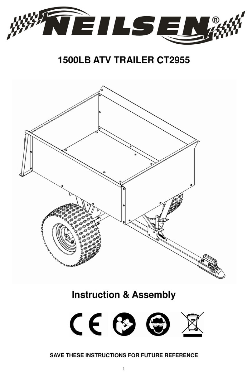
Neilsen
Neilsen CT2955 Instructions & assembly

Second Wind Trailers
Second Wind Trailers FREEDOM Faq

Club Car
Club Car Carryall 1 2001 owner's manual
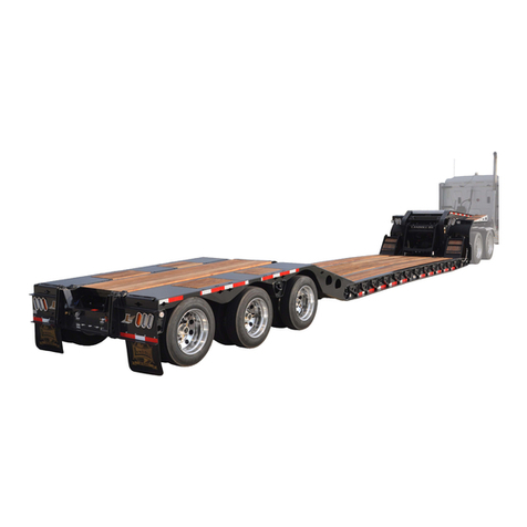
Landoll
Landoll 325C Operator's manual
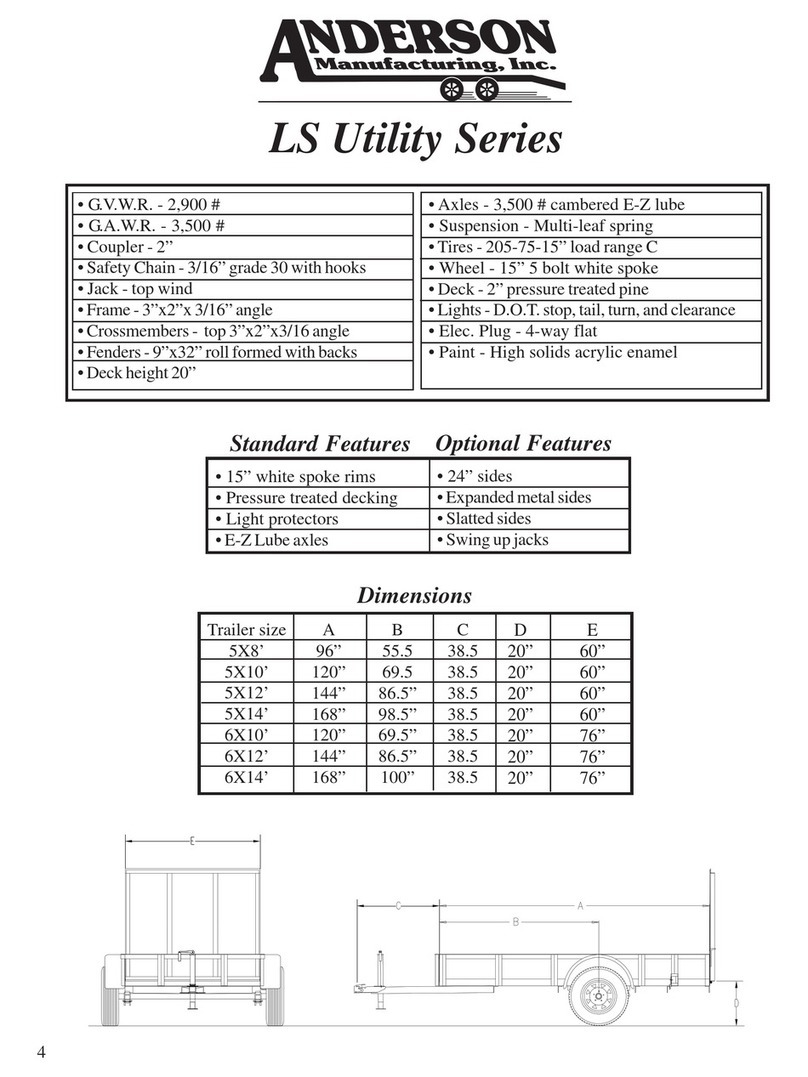
Anderson Manufacturing
Anderson Manufacturing LS Utility Series Specification sheet
