Fleetwood PAD-350 User manual

26043.6 -Fev./2009
INSTRUCTION MANUAL
MODEL PAD-350
POWER DRIVE UNIT
Persons under age 18 are not permitted to operate
or have accessibility to operate this equipment per
U.S. Dept. of Labor Employment Standards
Administration Fact Sheet N° ESA91-3.
ONE YEAR LIMITED WARRANTY
The original registered owner of this product
should contact SKYFOOD EQUIPMENT LLC at 305-868-1603 for any
warranty problems or service. SKYFOOD EQUIPMENT LLC will repair
or replace parts at our option for period of one year if unit fails to perform due
to defects in material or workmanship. Freight if required is at owner's
expense. Warranty does not include misuse or damage due to abuse as
determined by SKYFOOD EQUIPMENT LLC inspection. Units that are
70 lbs., or less are considered carry in and should be taken to an authorized
service facility.
Please read all safety instructions.
SERIAL #______________MODEL_______________
DETACH AND KEEP TOP PORTION
-------------------------------------------------------------------------------------
LIMITED WARRANTY REGISTRATION
OWNERS NAME
BUSINESS
ADDRESS
MODEL # SERIAL #
PURCHASED FROM
FILL OUT ABOVE INFORMATION AND MAIL OR FAX TO
SKYFOOD EQUIPMENT LLC:
Office: PO BOX 416702, Miami Beach, FL 33141-3230 –
Phone: 305 868 1603– Fax: 305 866 2704
Sales & Warehouse: 71 Bloomfield Ave, Newark, NJ 07104 –
Phone: 973 482 5070 – Fax: 973 482 0725
–
TOLL FREE 800 445 6601
[email protected] www.skyfood.us


INDEX
1
INSTRUCTION MANUAL
2. TECHNICAL CHARACTERISTICS
3. INSPECTION
5. CIRCUIT BREAKER
1. INTRODUCTION
2
2
2
4. SAFETY
3
4
6. OPERATION INSTRUCTIONS
7. LOADING PLATE UNITS INTO THE ATTACHMENT HOUSING
8. MOUNTING THE ATTACHMENT TO POWER SOURCE
9. PROCESSING PRODUCT
10. DISMOUNTING AND DISASSEMBLY FOR CLEANING AND
MAINTENANCE
11. LUBRICATION INSTRUCTIONS
12. PLATE USAGE
13. OPTIONAL: SHREDDER PLATES AND TYPICAL USAGE
14. MACHANICS MAINTENANCE
15. TROUBLE SHOOTING GUIDE
16. PROPER ASSEMBLY OF THE SLICER PLATE ASSEMBLY
4
6
6
7
8
9
10
10
11
11
9

1. INTRODUCTION
The PAD-350 drive assembly has been inspected and tested at the
factory, however, it should be externally inspected and electrically checked prior to use.
The electrical data listed on the nameplate should be the same as the user's electrical
supply. Any damage should be reported to the carrier immediately, and any shortage
or deviation of parts to Fleetwood Food Service Equipment 71 Bloomfield Avenue
Newark N.J. 07104 Phone 973-482-5070 / 800-445-6601 Fax 973-482-0725.
This manual contains instruction for the inspection, installation,
safe, operation, care, and maintenance of the PAD-350 Vegetable Slicer/Shredder.
Disassembly, repair, replacement and reassembly instructions are included. A trouble
shooting guide is provide. A complete replacement parts list with identifying figure
diagrams is included to aid in idenfication.
Please review this manual carefully particularly all safety precautions before trying to
put the PAD-350 into service.
2
The PAD-350 is a 1,5 HP portable electric unit consisting of a 12
drive hub operating at 350 rpm. It is designed to support and power a attachment
Vegetable Slicer and attachment Shredder and Grater food processing attachments
(Not included).
2. TECHNICAL CHARACTERISTICS
(*) Frequency will be in accordance with the supplied electric motor .
Table -01
Voltage
Motor rating
[V]
[Hz]
[HP]
[kW/h]
[inch]
[Lbs]
[Lbs]
Frequency
Consumption
Height
Width
Depth
Net weight
Gross weight
Characteristics Unit PAD-350
110
50 or 60 (*)
0,73
25,59
11,42
25,20
63,9
79,4
1,5
3. INSPECTION
11
15. TROUBLE SHOOTING GUIDE
Caution: Review all safety notes and disconnect electricity to
power source equipment before attempting corrective measures.
16. PROPER ASSEMBLY OF THE SLICER PLATE ASSEMBLY
CAUTION: The thrust bearing must be securely tightened before the
slicer plate assembly is loaded into the housing. Failure to tighten will damage the
attachment the power source equipment. NOTE: The thrust bearing requires a left hand
twist to tighten.
Figure 10
[inch]
[inch]

3
4. SAFETY
"It is a violation of United States Department of Labor regulations to
per operation of this unit by any person under the age of 18 years."
The user should read and understand the PAD-350 and the attachment
instructions prior to operation. First time operators should be properly trained in safety
precautions and in the proper use and servicing of this equipment and attachments.
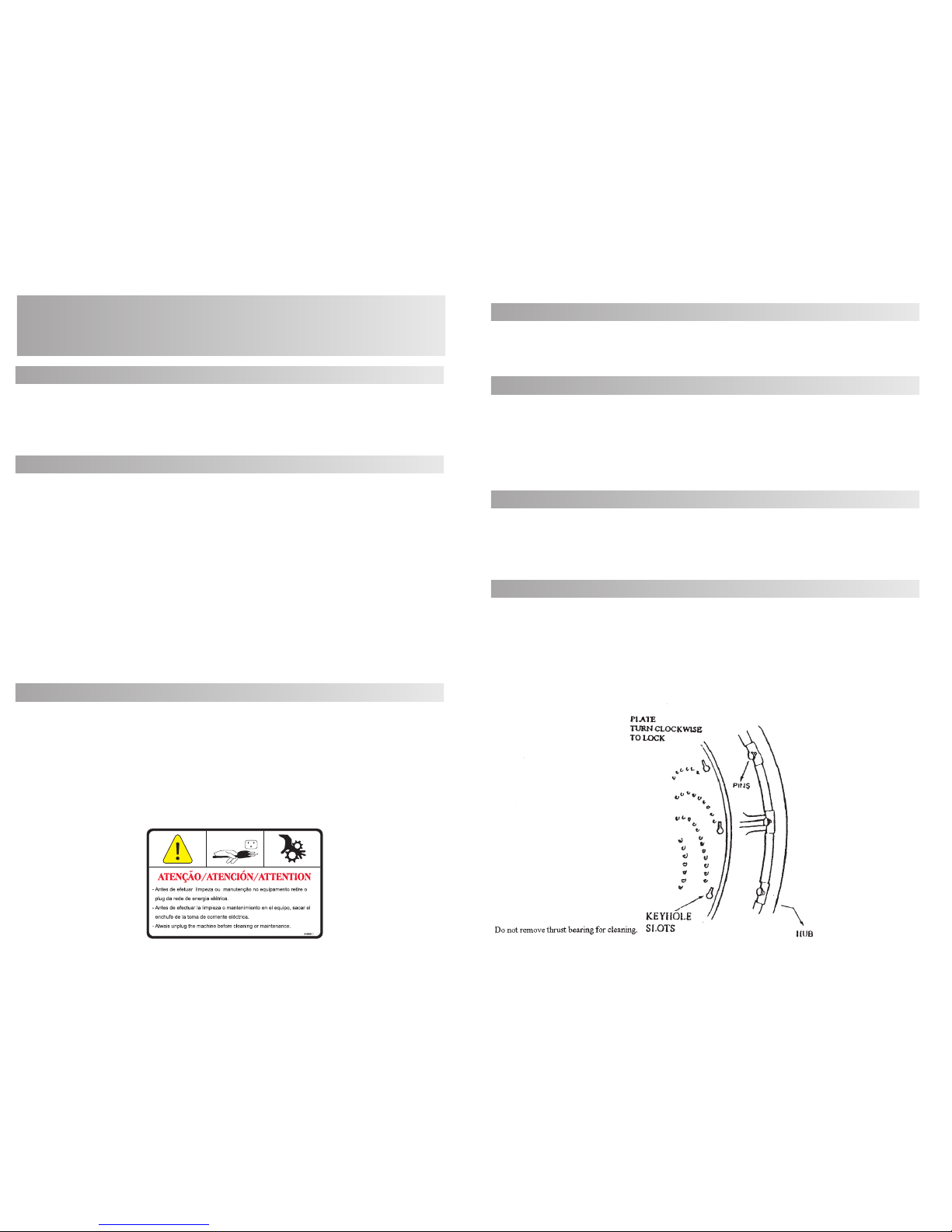
Switch the power "OFF" and disconnect the electrical suply before
mounting or disengaging an attachment, or for cleaning and servicing the equipment.
Before, connecting unit to power source it should also be in the "OFF"
position.
-Never insert hands into the hopper.
-Never insert any utensil into the hopper.
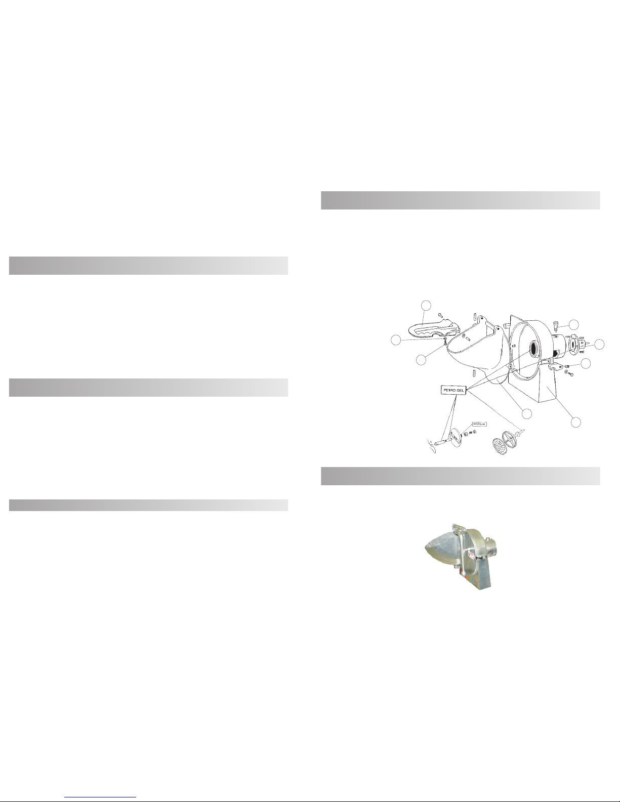
4.1. Note that the front housing of the attachment has a feed hopper. It
is also equipped witha a feed plate. Food to be processed must always be fed to cutting
surfaces by way of the hopper, and compressed against cutting sufaces with the feed
plate. Never try to feed product to cutting surfaces with your hands or any other way!
4.2. If during operation of a product jam occurs, immediately turn off
and disconnect the electrical supply to the power source equipment. Make sure rotation
has stopped. Unlatch the attachment's front housing, swing it toward you and then clear
the obstruction. Do not try to clear obstructions while the attachment is under power, and
again, never insert fingers or utensils into the hopper!
4.3. Wear protective gloves whenever handling the attachment's
knives, cutting plates, or cutting assemblies. They are very sharp and can cut you. For
safety, wash knives and cutting plates with a long handled scrub brush.
4.4. When assembling or disassembling the attachment, make sure it
rests on a stable working surface. Never rest knives, cutting plates or cutting assemblies
on surfaces that could be marred.
4.5. Before assembling the attachment and mounting it to power
source equipment, make sure that a comfortable working clearance has been
provided around the machinery. Always install the machinery where it will save the
operator steps.
4.6. Before assembling the attachment and mounting t to power
source equipment or dismounting the attachment after use, disconnect or lockout the
electrical supply to the power source equipment. This will prevent any chance of
accidental startup.
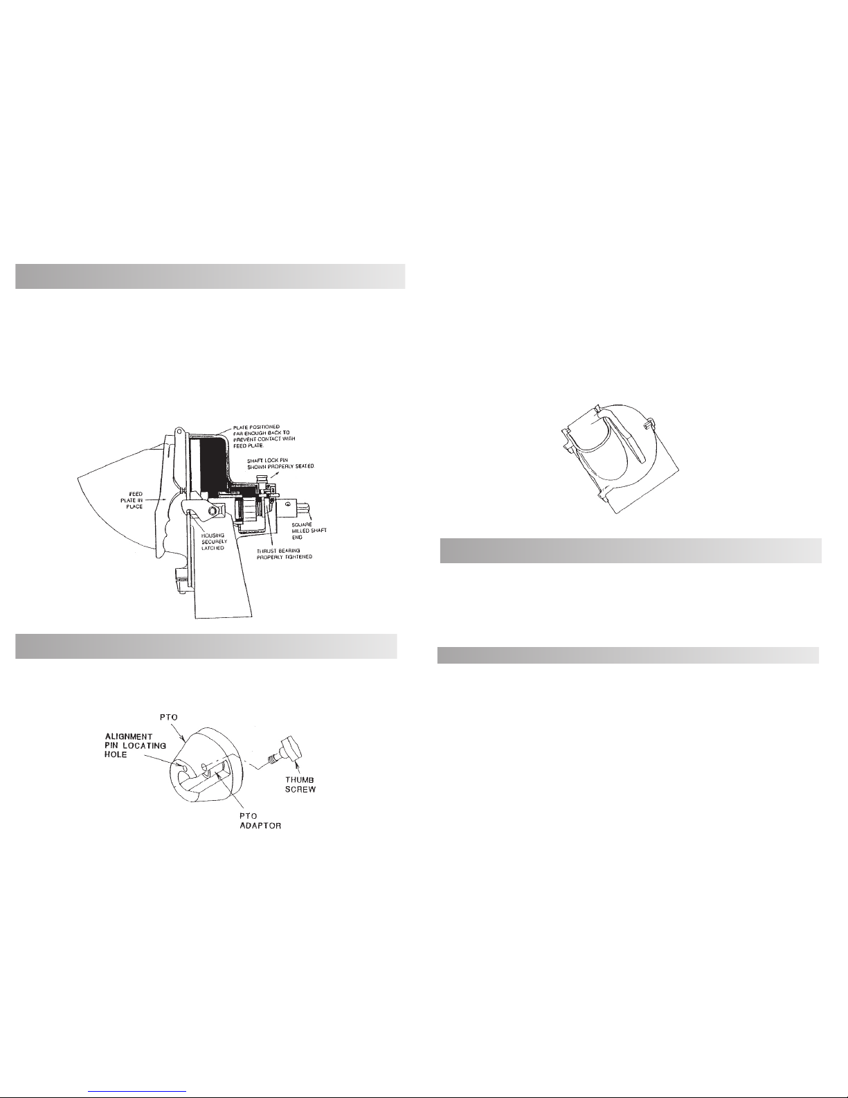
4.7. Before mounting the attachment to power source equipment,
make sure the front housing is securely latched to the rear housing.
10
Slicing Adjustable "S" knife assembly with stainless steel knife. Typical
usage:
LETTUCE - CUCUMBERS - CARROTS - CELERY - RADISHES - CABBAGE - PEPPERS - POTATOES -
CHINESE VEGETABLES - ONION - ZUCCHINI
Shredding assembly, with 5/16 Shredder Plate.
13. OPTIONAL: SHREDDER PLATES AND TYPICAL USAGE
Before trying to maintenance the attachment, review the safety
precautions paragraph carefully, and read all assembly-disassembly instructions on
Pages 2-6. Wear gloves when handling plate units.
Since the attachment contains no internal power source, most problems
can be immediately traced to improper assembly, improper adjustment or worn parts.
The Trouble Shooting Guide on Page 11 lists the most common problems and corrective
measures.
14. MECHANICS MAINTENANCE
Figure 7
Figure 8
(Not included)
(Not included)

4
4.8.The thumb screw shoub be firmly snugged immediately after
mounting the attachment to secure the attachment in place. Do not operate the
attachment if there is no securing device present on the power takeoff hub.
4.9.Never hose down a attachment mounted to power source
equipment. Hosing down a mounted attachment invites electrical shock.
5. CIRCUIT BREAKER
If the circuit breaker HAS TRIPPED, turn the power switch to "OFF" and
disconnect the electrical supply, determine and then correct the fault before resetting.
To prevent unauthorized use, remove the switch key.
Be sure the attachment is properly cleaned, assembled and installed,
tighten thumb screw before connecting to power source. Do not attempt to service the
drive assembly. Please contact Fleetwood Food Service Equipment for the number of
the nearest authorized service agent in your area.
6. OPERATION INSTRUCTIONS
The PAD-350 should be setup in an area that is convenient for operation
and has sufficient clearance for safety. Before installing the attachment, make sure the
PTO adapter is properly installed on the drive shaft. The vegetable slicer should be
attached with a twisting motion and in an upright position. Make sure to tighten the
thumb screw. When processing foods please observe operating and safety instructions.
When processing is completed, turn "OFF" and disconnect power source. Remove the
attachment, disassemble, clean, dry and sanitize before storing in a clean, dry
environment.
6.1. CAUTION
The PAD-350 should not be used for any of the applications listed
below. Failure to observe these guidelines may result in damage to PAD-350 and will
void the manufacturer's warranty.
-Do not use the PAD-350 to drive a meat grinder acessory!
9
LUBRICATION
After every cleaning, apply a thin coating of sterile petroleum jelly to all bearing
surfaces. Do not use vegetable oil. It becomes gummy. If adjusting nuts and screw stiff
to work with, apply a drop of sterile mineral oil.
11. LUBRICATION INSTRUCTIONS
12. PLATE USAGE (OPTIONAL)
STANDARD EQUIPMENT Satin finish Aluminum Housing with hinged chute
door, latch and feed pusher, n° 12 rear hub and locking pin.
(NOT INCLUDED)
Figure 5
Figure 6
1. FRONT HOUSING
2. REAR HOUSING
3. SHAFT LOCK PIN
4. REAR HUB
5. FEED PLATE
6. STOP NUT
7. SCREW
8. SET SCREW
1
2
4
8
5
6
7
3
(NOT INCLUDED)

5
CAUTION: Again, wear hand protection when working with these units.
6.2. PLATE ASSEMBLY
To assemble the slicer plate, see Figure 10 component assembly
order and fit as shown. The plate, when assembled, can be adjusted to slice product to
different thickness by turning the "adjusting nut" per the directions accompanying
Figure 10.
6.3. ADJUSTABLE SLICER PLATE ASSEMBLY (OPTIONAL)
Adjustments for thickness must never be attempted while the
attachment is under power or severe personal injury can occur. See safety precautions.
6.4. WARNING
To fit the plate of your choice to the hub and shaft (FIG. 01), line up the
key hole slots on the plate with the locating pins on the hub as shown below. Slip the
plate over the pins and secure it by turning the plate in a clockwise direction until it
shoulders up firmly on the pins. This can be done most safely by resting the plate face
down on a butcher's block and turning the hub home from above.
6.5. SHREDDER PLATE ASSEMBLY (OPTIONAL)
Figure 1
SLOT AND PIN ALIGNMENT
8
To dismount the attachment, simply follow the mounting instructions on
Page 6 and 7 in reverse order. Set the attachment on a stable working surface.
10. DISMOUNTING AND DISASSEMBLY
FOR CLEANING AND MAINTENANCE
10.1.DISMOUNTING
To disassemble the attachment for cleaning or maintenance:
10.2.1. Unlatch the front housing and swing it toward you.
10.2.2. Lift the feed plate up and urge it to the left until it pivots off the
front housing and set it aside.
10.2.3. Lift the front housing from its pivot holes and set it aside.
10.2.4. To disassemble the plate units, follow the assembly instructions
on Page 5 and 6 in reverse order. Set the components aside.
10.2. DISASSEMBLY
To avoid damaging the attachment's highly polished finish, never put
any attachment component through a dishwahing machine. Wearing hand
protection, wash all components by hand with a mild soap and water solution. Use a
long handled scrub brush on all plate units to avoid finger cuts. Again, do not rest knives
or shredding plates on any surface which will mar. Do not remove thrust bearings from
Shredder plate shafts. Dry component parts with a soft dry rag.
For the best and most sanitary product, clean the attachment
immediately after use of before switching food products.
10.3. CLEANING

6
With the attachment resting on a stable working surface, unlatch the
front housing (FIG. 5 Nº 1) and swing it toward you. Lift the assembled plate unit and
insert it into the rear housing (FIG. 5 Nº 2). Lift the shaft lock pin (FIG. 5 Nº 3) and seat the
plate unit with a gentle twist. Make sure that the thrust bearing on the shaft has carried
fully into place, and that the square milled end of the shaft has fully cleared the rear hub
(FIG. 5 Nº 4). Release the shaft lock pin, then close and securely latch the front housing.
The attachment is now ready to mount to power source equipment.
7. LOADING PLATE UNITS INTO THE ATTACHMENT HOUSING
Figure 2
PROPERLY LOADED VSA9/VSAG
Again, before mounting the attachment, make sure that the power
source equipment is turned off and its electrical supply disconnected or locked out.
8. MOUNTING THE ATTACHMENT TO POWER SOURCE
Figure 3
TYPICAL POWER TAKEOFF HUB
7
Carefully lift the attachment and insert the square milled shaft end into
the hub intake port (See figure above), while the attachment at the angle pictured
below.
Slide the attachment forward until the square milled shaft end firmly
seats in the PTO adapter (Fig. 3) Gently twist the attachment to a fully upright position,
slide locating pin into PTO locating hole and snug the thumb screw (Fig. 3). NOTE: Only
the #12 tapered hub is fitted with a locating pin. The attachment is now ready to
process product.
Figure 4
MOUNTING ANGLE
(NOT OPERATING ANGLE)
Before processing product, please review the plate usage chart on
Page 10 and please note that the feed plate (FIG. 5 Nº 1) is equipped with an adjusting
nut and screw (FIG. 5 Nº 6 and 7). This assembly should be adjusted until there is no
chance plate being compressed against cutting surfaces. If the feed plate meets a
rotating cutting surface, both components will be damaged.
9. PROCESSING PRODUCT
Reconnect the electrical supply to the power source equipment, turn
the PAD-350, on.
Lift the feed plate to expose the plate unit, and drop product into the
feed hopper. Keep hands clear. With you hand holding the feed plate grip, gently
compress product against the rotating plate unit.
If you experience problems in processing, shut down the power source
equipment and refer to the Trouble Shooting Guide on Page 11 and the safety
precautions paragraph.
9.1. TO PROCESS:
(Not included)
Table of contents