FLEMING ST1100N User manual

EU CERTIFICATE OF CONFORMITY
CONFORMING TO EC Machinery Directive 98/37 EC
We:
Fleming Agri-Products Ltd
Newbuildings Industrial Estate
Newbuildings
Northern Ireland
BT47 2SX
declare in sole responsibility, that the products
Type: ST1300N,ST1600N,ST1600,ST2000 Slurry Tankers
to which this certificate applies, conforms to the basic safety
and health requirements of the EC Machinery Directive 98/37 EC,
and the Transposed Harmonised Standards:
BS EN 4254-1 (2009)
ST1100N,ST1300N,ST1600N,
ST1600,ST2000,ST2400
Slurry Tankers
Fleming Agri-Products Ltd
Newbuildings Industrial Estate
Newbuildings
Northern Ireland
BT47 2SX
Tel: (028) 7134 2637
Fax: (028) 7134 4735
Email:info@fleming-agri.co.uk
www.fleming-agri.co.uk
‘Quality, Strength & Personal Service’

This manual is provided to assist you in getting the best results from your
Slurry Tanker and ensure that you do so safely. If you have any queries
about the use of the Slurry Tanker contact your dealer before use. Please
keep this manual for future reference.
The Fleming range of Slurry Tankers are robustly designed and manufac-
tured to cater for all size of operations. The full length drawbar attached to
the axle reduces stress on the tank. The tank is coated internally with a pro-
tective coating for extended life. All Fleming Slurry Tankers are fitted with
the new series Battioni MEC/M vacuum pump which allows for longer con-
tinuous working periods than that recommended for traditional agricultural
pumps.
Currently there are four models within the Fleming Slurry Tanker range.
The table below specifies the standard equipment which is supplied with the
Slurry Tanker range. (See Table 2. for respective capacities).
1.1 FUNDAMENTAL PRECAUTIONS
On delivery, your dealer gave you an explanation of the operation and
maintenance of this Fleming Slurry Tanker. Please read and understand
these operating instructions before operating the machine for the first time.
It is essential that you observe all safety instructions.
Incorrect use or mishandling of the Slurry Tanker can endanger:
Life and Limb of the operator, other persons or animals within the vicinity
of the machine.
The machine and other material assets of the owner or third persons.
The performance of the Slurry Tanker
Anyone who is involved in the commissioning, operation or maintenance of
the Slurry Tanker must read and understand these instructions very careful-
ly and observe them at all times.
Table 1. Standard Equipment
Model
Capacity
Gallons
Wheels
Rec‟d
MEC
Pump
Hyd
Brakes Lights
Standard
Tyres
ST1300N 1300 No 8000M Yes Yes 550/65/22.5
ST1600N 1600 No 8000M Yes Yes 550/65/22.5
ST1600 1600 Yes 8000M Yes Yes 28.1 R26
ST2000 2000 Yes 11000M Yes Yes 28.1 R26

Never enter the area directly under the tanker and stand clear of the
danger zone when the wheel is removed
Prop axle with heavy duty axle stands as close as possible to the wheel
that is to be removed. Make sure the placing of the axle stand is the very
first part of the procedure and make sure the axle stand pins are of
correct specification.
Do not exceed the rated capacity of the axle stand. The weight that will
need to be jacked up will not exceed 2000kgs provided the slurry tanker
has been emptied properly.
Do not lift tanker off the ground by top crane hook when changing a
wheel.
Do not use a trolley jack or bottle jack when changing a wheel as they will
not have sufficient travel height.
AXLE STAND
1.2 AUTHORISED OPERATORS
Youths under the age of 16 must not operate the Slurry Tanker. The owner of
the machine must provide the operator with the operating instructions and
make sure they have read and understood them. Only then may the Slurry
Tanker be put into operation.
The owner must ensure that only authorised persons operate/work on this Slur-
ry Tanker. He is responsible for keeping any third persons or animals out of the
working area of the Slurry Tanker.
A SAFE DISTANCE OF AT LEAST 10M MUST BE OBSERVED BY ANYONE
WITHIN THE VICINITY OF THE SLURRY TANKER.
1.3 GENERAL SAFETY AND ACCIDENT PREVENTION REGULATIONS
Before operation make yourself familiar with all elements and controls of the
Slurry Tanker as well as their functions.
Ensure the Slurry Tanker is correctly and securely attached to the operating
vehicle. The recommended method of attachment is to use the tractor hook
hitch.
Always check that the hydraulic brake line is connected and functioning.
NEVER attach to a tractor which would be rendered unstable when the Slurry
Tanker is operated at its full capacity. Take note of the maximum load permissi-
ble on tractor draw bar.
The attaching and detaching of the Slurry Tanker to a tractor must be carried
out by only one operator. There should not be any other people in the vicinity
of the implement or in the tractor.
When detaching the Slurry Tanker from the tractor always ensure that it is safe-
ly positioned on a level surface and that blocks are positioned below each
wheel.
Table 2. Slurry Tanker Capacities
Model Unladen Weight (kg)
Approximate
Laden Weight (kg)
Capacity
(Litres)
ST1300N 2100 8012 5910
ST1600N 2280 9433 7274
ST1600 3340 10020 7274
ST2000 3500 12250 9092

NEVER allow children to play on or around tractors and machinery.
NEVER operate the Slurry Tanker unless all safety guards are fitted and are
firmly in position. ALWAYS ensure that all guards and covers are replaced
after carrying out maintenance or adjustments.
Do not make any sharp turns with PTO shaft in motion.
ALWAYS disengage the PTO before dismounting from the tractor.
Operators should not wear loose fitting clothing when working close to PTO
driven equipment. Keep long hair tied back. NEVER be in the vicinity of a
rotating PTO shaft.
ALWAYS disengage the PTO shaft, apply the hand brake, stop the tractor
and remove the key before carrying out any maintenance or adjustments to
the Slurry Tanker.
Before operation inspect the area around you. Keep children away. All visi-
tors and unauthorised persons should be kept well away from work area.
NEVER operate the Slurry Tanker with persons standing in the spreading
path. There is a danger of serious injury to both livestock and persons with-
in this area. A safe distance of at least 10m must be observed by anyone
within the vicinity of the Slurry Tanker.
Take extra care when operating the Slurry Tanker on sloping ground. .
Exercise extreme caution when turning on sloping ground. Especially with a
partially filled tanker as the inertia will cause the weight of the contents of
the tank to be thrown to one side of the tank. NEVER operate on ground
where there is a risk of the tractor becoming unstable
NEVER park the tractor and Slurry Tanker on a slope.
NEVER attempt to move the Slurry Tanker manually.
To avoid personal injury keep hands and limbs well away from the moving
parts.
Under NO circumstances should anyone, authorised or otherwise attempt
to use the Slurry Tanker as a means of personal transport. It is designed as
a special purpose farm implement and is unsuitable for the safe transporta-
tion of passengers. NEVER allow anyone especially children to travel any-
where between the tractor and an implement.
Where local laws permit ensure that a flashing amber beacon is mounted on
the cab of the tractor and is always used when transporting the Slurry Tank-
er on the road.
Always ensure that the rear view mirrors on the tractor are adjusted properly
and are kept in good order.
Fill pipe with identical ends connected to fill
points of separate tankers, used to empty tanker
that needs wheel changed.
Locations of jacking points are clearly labelled at the back of the tanker.

2.0 WHEEL CHANGING PROCEDURE
It is compulsory to employ a professional tyre fitter to carry out any
wheel changing maintenance. The tyre fitter must follow these
instructions carefully.
The slurry tanker must be connected securely to the tractor with
wheels chocked to minimise movement before wheel changing pro-
cesses can begin.
The slurry tanker must be emptied before any wheel changing
maintenance can begin. The tanker can be emptied into another va-
cant slurry tanker by means of one fill pipe with 2 identical connection
ends. Each end of the fill pipe can be connected to the fill points of the
2 separate tankers. When emptying the tanker, it is important to suck
into the empty tanker rather than blow from the full tanker.
When changing a wheel, always position the tanker on a hard, level
surface and if carrying out the procedure on a public highway,
consider the gradient of the camber before jacking or propping.
Jacking mechanism should have an extension of approximately
400mm to allow enough clearance for tyre to come off and to be put
on again when fully inflated. It is also highly recommended to use an
air actuated jack so that the tyre fitter can stand well clear of the slurry
tanker while Jacking.
Consult with your professional tyre fitter to determine if the tyre can be
fixed without removing it from the slurry tanker.
If the wheel must be removed, ensure that an axle stand prop is
appropriately positioned before the wheel is removed.
DO NOT PROP WITH DECAYED, UNEVEN TIMBER OR CEMENT
BLOCKS. Use appropriate timber as shown below.
Never enter the danger zone when the wheel is removed.
Jacking points must be
checked at regular intervals
and if damaged contact your
local dealer immediately.
SLURRY GASES CAN KILL. Vacate slatted houses of animals and people
when mixing is in progress. Do not stand near tank openings or stoop to floor
level when mixing. Secure suction hoses to prevent them from falling into the
tank. Do not enter a below ground level tank. If unavoidable attach a lifeline
held by two persons.
SLURRY GASES CAN BE FLAMMABLE. Never allow naked flames near the
tanker or tank openings.
NEVER open the rear door to enter the tanker without first decompressing the
tanker and venting all gases. If entering the tanker always have another person
standing by.
Before attempting to clear any blockages in the spread plate, ensure the pump
lever is in neutral, the tank is depressurised and the rear discharge valve is
closed.
NEVER DISTRACT PERSONS WHO ARE USING THIS MACHINE.
1.4 PTO SHAFT LENGTH
The PTO shaft length may be altered to suit individual tractors. During opera-
tion when the PTO is at its maximum extended length there must be a mini-
mum overlap of 1/3 PTO shaft length as shown in the minimum PTO overlap
diagram.
The Slurry Tanker should be hitched to the tractor and be checked in various
positions to ensure that the PTO drive line is the correct length. Remember
that undulating ground can also affect the length of the PTO shaft.
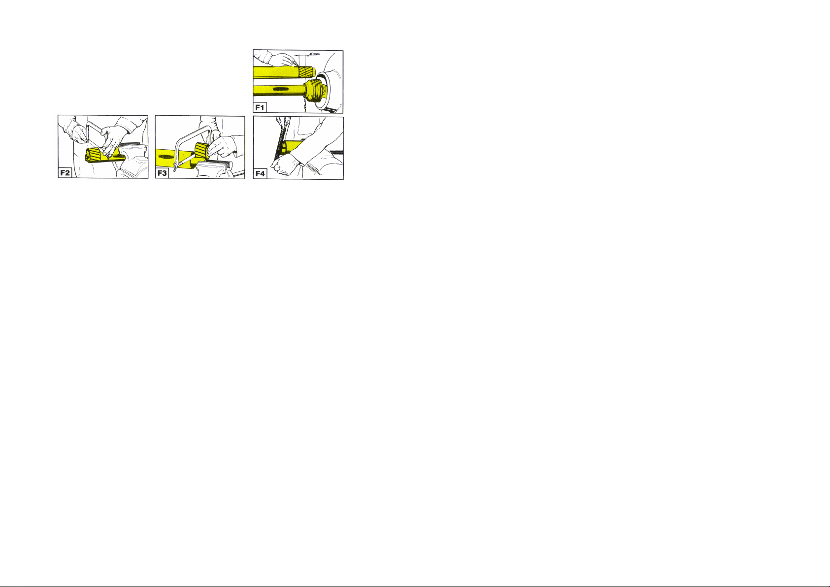
SHORTENING THE PTO SHAFT.
Set the tanker at its minimum distance from the tractor. Brake the tractor
and switch off the engine.
Separate the PTO. Attach the female part to the tractor PTO and the male
part to the tanker pump PTO. Ensure that the fixing pins have “clicked” into
position and are engaged.
Keeping the two halves of the PTO parallel line them up side by side. Fig 1.
Match mark where the two halves are to be shortened. Fig 1.
Taking one half of the PTO cut the shield at the mark. Fig 2.
Using the cut off piece as a guide (fig 3) cut the shaft.
Proceed in the same way with the other half of the PTO.
Trim and de-burr the two cut ends of the PTO and clean off all swarf. Fig 4.
Grease the two profiles and join the two halves of the PTO together.
Fit the PTO shaft to the tractor and tanker and check as before that its
length is correct ensuring that minimum overlap advice is observed and
that the PTO does not bottom when turning.
If the PTO is too short with a tendency
to separate, then it must be replaced
with a longer one.
If the PTO is too long, it should be
shortened using the following method.
1.9 HYDRAULIC SAFETY
The Slurry Tanker discharge valve and brakes are hydraulically operated. These
safety considerations should therefore be adhered to.
CAUTION The hydraulic system is under high pressure.
Ensure that only high-pressure hoses are used to connect supply to the Slurry
Tankers hydraulic cylinder(s). Check hoses regularly and renew any that are
damaged or worn.
Before working on the hydraulics release the pressure from the hydraulic sys-
tem and stop the tractor engine.
When connecting hydraulic rams make sure that the hydraulic hoses are cou-
pled correctly. Pressure should be released from the system both on the tractor
and on the implement side prior to coupling the hoses to the tractor hydraulics.
CAUTION Hydraulic oil forced out under pressure can break the skin and cause
severe injury. In the event of a hydraulic oil leak stop the tractor flow immedi-
ately. DO NOT PUT HANDS NEAR A LEAKING PIPE.
1.9 HYDRAULIC SAFETY
The Slurry Tanker discharge valve and brakes are hydraulically operated. These
safety considerations should therefore be adhered to.
CAUTION The hydraulic system is under high pressure.
Ensure that only high-pressure hoses are used to connect supply to the Slurry
Tankers hydraulic cylinder(s). Check hoses regularly and renew any that are
damaged or worn.
Before working on the hydraulics release the pressure from the hydraulic
system and stop the tractor engine.
When connecting hydraulic rams make sure that the hydraulic hoses are cou-
pled correctly. Pressure should be released from the system both on the tractor
and on the implement side prior to coupling the hoses to the tractor hydraulics.
CAUTION Hydraulic oil forced out under pressure can break the skin and cause
severe injury. In the event of a hydraulic oil leak stop the tractor flow
immediately.
DO NOT PUT HANDS NEAR A LEAKING PIPE.

1.8 OVERALL DIMENSIONS
Model Overall Length
(including
Sprinkler)
Width over
tyres
Height
ST1300N 6.275 metres 2.56 metres 2.65 metres
ST1600N 6.990 metres 2.56 metres 2.65 metres
ST1600 6.990 metres 2.49 metres 2.79 metres
ST2000 7 .00 metres 2.49 metres 2.99 metres
1.5 GENERAL OPERATING INSTRUCTIONS
Observe all maintenance requirements (See Section 1.7) and ensure operator
is competent with machine before commencing operations.
Before using the vacuum pump ensure that the PTO shaft is turning freely and
the direction of rotation is the same as indicated by the arrow on the pump.
Never turn the vacuum pump shaft in the opposite direction to that indicated
as this could damage internal components of the pump.
The Battioni MEC/M new series pump with long life blades may be continu-
ously operated for 15 minutes. However, prolonged uninterrupted working
times may cause excessive heating of the pump and damage to the vanes. If
it is expected that the pump will be used for a longer period because of the
density of the slurry to be processed then dilute or mix the slurry.
Operating pressure should be kept within the range of 0.5 – 0.9 bar to avoid
overheating the pump or breaking the vanes. Do not exceed 0.9 bar.
Ensure that oil drip feed is at the correct setting.
Regularly check the pump oil level.
Check the wheel nuts and wheel bearings daily for tightness.
Check daily that the discharge valve tongue fully opens. If it does not then re-
move the top of the valve complete with the ram by loosening the six socket
head screws securing the top valve housing to the main body. Clean out any
debris in the housing. The valve rod will break if this procedure is not carried
out.
The emergency breakaway handbrake should be connected to the tractor
every time the Slurry Tanker is used. The connection should be via a rope
attached to a solid part of the tractor such as the top link and not to a panel.
The rope should be tight enough for the handbrake to be operated if the tank-
er becomes detached from the tractor but loose enough so that the handbrake
is not applied during normal operation.

1.6 SLURRY TANKER OPERATION
Filling Procedure.
Read the sections in this manual regarding safety and maintenance.
Attach the suction filling hose to the quick attach fitting located at the rear of
the tanker.
Open the manual rear fill inlet valve with the operating handle.
Ensure that the end of the fill pipe is completely submerged before opera-
tion.
Ensure the vacuum pump oil drip feed is set to 1 drop every 3 seconds
Set the vacuum pump operating lever in the Suction position.
Engage the PTO at low rpm and increase to 350 rpm.
When slurry appears in the sight glass at the rear of the tanker, shut the in-
let valve with the operating handle.
Move the vacuum pump operating lever to the Neutral position.
Remove the suction fill pipe.
Spreading Procedure.
On arrival at the spreading site set the pump operating lever to the Pres-
sure position.
Engage the PTO at approximately 350 rpm while driving forward. Using the
hydraulic control, open the gate valve to the discharge unit at the rear of the
tanker.
TYRE PRESSURES
RECOMMENDED LUBRICANTS
GREASE
OIL
Brake Adjustment
It is highly recommended that brake adjustment is only carried out by
qualified service engineers.
For the safe operation of the tanker it is imperative that a routine mainte-
nance schedule is developed for cleaning, inspection, adjustment and
lubrication of brake components.
Adjustment of brakes should be carried out as frequently as required to
maintain safe operation. When resetting brakes. The hydraulic brake ram
should be 38mm – 50mm from the end of its stroke when the brake shoes
engage the hub.
At regular intervals remove the brake drums and check linings for wear and
the drums for cracks, scoring or any other form of deteriation.
Tyre BAR PSI
550/65-22.5 229
28.1 R26 229
Manufacturer Recommended Alternative
Shell Shell Retinax LX2 Shell Retinax LX
Mobil Mobil Grease H.P .222 Mobil Grease H.P.
Castrol Castrol LMX Spheerol A.P.T.Z.
Texaco Hytex EP2
Esso Unirex EP2
BP Energrease LC2
Manufacturer Application Recommended Alternative
BATTIONI
PAGANI POMPE Vacuum Pump oil
reservoir
Vacuum Pump Oil
VPO005BP
SAE20 (SAE30
in summer)
Any of the
above
Vacuum Pump
gearbox
EP90 Hypoid

MAINTENANCE SCHEDULE:
Grease the following Initially 8
hours
40 hours 160 hours
PTO shaft universal joints ··
PTO Shaft Male profile ··
Brake Cams ··
Wheel Hub Bearings ··
Check Initially 6 hours 40
hours
160
hours
Oil Drip Feed ··
Vacuum Pump Oil Reser-
voir level
··
Vacuum Pump Gearbox
Oil Level.
··
Gate Valves for blockages ··
Rear Door for leaks ··
Regular Tasks Initially 6 hours 40 hours 160 hours
Tighten nuts ··
Flush 1 litre of diesel
through Vacuum Pump
air intake with handle set
in the pressure position
··
Hydraulic hose
& 12v cable
Vacuum Pump Drawbar Springs
Road Lights
Site Glass
Rear Fill Port Quick
Attach Fitting.
Rear Fill Inlet Valve
Operating Handle
Rear Discharge Hy-
draulically Operated
Rear Discharge
Unit
Backdoor
Primary Float
Secondary
Float Valve
Front Side Fill Port
PTO INPUT
1.7 MAINTENANCE
As a rule, disengage the driving system and stop the engine prior to carrying
out maintenance, servicing, cleaning or repair work. ALWAYS remove the
ignition key.
Chock the machine with appropriate wheel chocks before carrying out any
maintenance work.
The manufacturer will not be responsible for any damages or injuries caused
by unauthorised repair, alterations or mishandling of the product.
Maintain the product with care. Check periodically for damage that would
affect the safe operation of the Slurry Tanker.
Regularly check all bolts and tighten if necessary.
Regularly lubricate the hydraulic cylinder, bearings and drawbar hinge bush-
es using clean grease.
Only use clean grease complying to Din 51502.
ALWAYS ensure all warning stickers are kept clean and in good condition.
CAUTION paintwork may be damaged if high-powered washers are used
when cleaning the Slurry Tanker.
Do not carry out any welding of the tank without opening the back door.
Check tyre pressures daily. An under inflated tyre on one side will cause se-
vere stability problems on undulating ground.
VACUUM PUMP MAINTENANCE.
Periodically check the oil level in the gearbox at the front of the pump. The
oil level should be at the top of the see through plug.
Change the gearbox oil after the first 50 working hours and then every 300
working hours. Use EP90 hypoid gear oil.
Check daily that the level of the cooling oil is always above the bottom mark
on the dip stick. Top up using Battioni Vacuum Pump oil or engine oil SAE20
(SAE30 summer).
Check that the cut out valves (Primary & Secondary Float Valves) are in full
working order and that the rubber balls are not soft and spongy. These
should be replaced every 12 months.
After every working day flush out the pump with diesel oil. This will prolong
the life of the vanes in the pump. To do this set the pump to Pressure and
suck 1 litre of diesel in through the air intake. As a further precaution suck a
small amount of oil into the pump to lubricate it and minimise corrosion.
If the tanker is to be stored unused for a period of time then disconnect the
hose that connects the pump to the tank. This will avoid the transfer of corro-
sive gases from the tank to the pump.
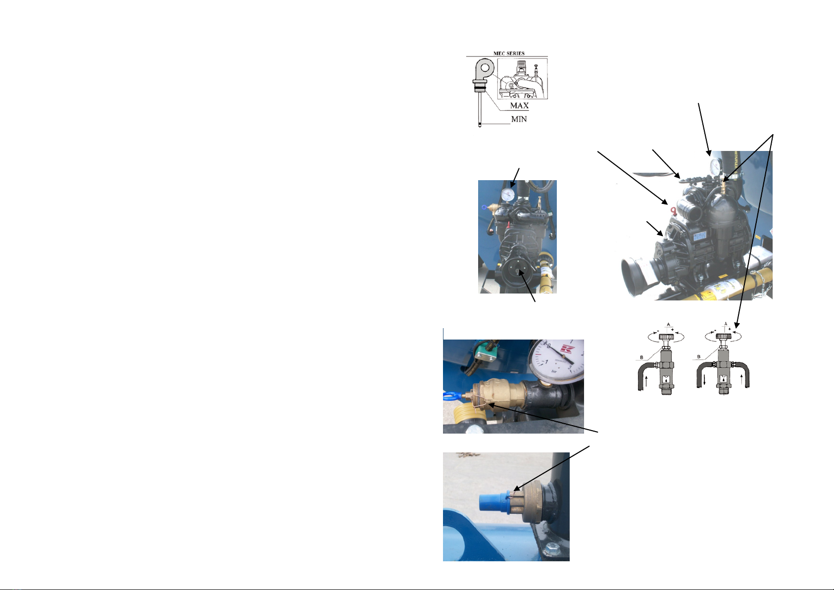
Vacuum Pump
Pressure Gauge
PTO Input
The minimum oil level is
indicated by the groove
at the bottom end of the
dipstick. Maximum is at
Oil Fill & Oil Level
Pressure Gauge
Oil Drip Feed
Pump handle.
P - Pressure
N - Neutral
V - Vacuum
Gearbox Oil Fill
Oil Drip Feed Adjustment
Loosen locknut „B‟ and turn the regu-
lator screw „A‟ until a flow rate of
one drop every three seconds is
obtained. Re-tighten locknut „B‟ after
adjustment.
WARNING
Pressure release valve comes preset at 0.9 bar and should
only be adjusted by a fully qualified service
engineer.
The decompression valve is preset at –0.7 bar and this also
should only be adjusted by qualified service engineers.
DO NOT USE THE TANKER IF THE SAFETY RELEASE
VALVES ARE NOT TIED WITH WIRE AS SHOWN IN THE
PICTURES.
SAFETY RELEASE VALVE
DECOMPRESSION VALVE
WIRE TIE
This manual suits for next models
5
Table of contents
Other FLEMING Utility Vehicle manuals

Popular Utility Vehicle manuals by other brands


Woodland Mills
Woodland Mills BUSHLANDER Operator's manual

Kendon
Kendon Stand-Up TRIKE/SPYDER/SIDECAR Ride-Up SRL owner's manual

Primo Water
Primo Water UT5x8-26HSS Assembly instructions

Joyner
Joyner JNSZ800MV owner's manual

Ammann
Ammann AP 240 operating manual

Carry-On Trailer Corporation
Carry-On Trailer Corporation 7x16CG User's manual - safety guide


