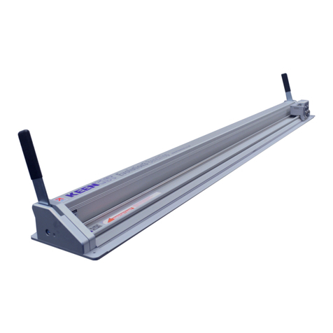
FLETCHER F-60 User manual

OWNER’S MANUAL
Fletcher F-60 Cutter
The Fletcher-Terry Company
91 Clark Drive • East Berlin, CT USA 06023
Tel 860.677.7331 • Toll-Free (U.S. only) 888.888.5165 • Fax 860.828.3400
Form ENG - 052212

TABLE OF CONTENTS
INTRODUCTION…………………………………………………………………………….. i
PRODUCT WARRANTY……………………………………………………………………. i
SAFTEY FIRST………………………………………………………………………………. ii
I. OPERATION OF THE F-60 CUTTER
a. Unpacking materials………………………………………………...………….. 1.
b. Operating Rail Clamp Mechanism……………………………………………. 2.
c. Plastic Knife Blade Cartridge………………………………………………….. 2.
d. Inserting Plastic Knife Blade…………………………………………………... 3.
II. Trimming Green Sight-Line Strip to Size………………………………………... 3.
III. F-60 Cutting Head – Operating Lock and Cut Feature………………………... 4.
IV. General Maintenance Tips…………………………………………………………. 4.
V. F-60 Cutting Head – Field Adjustment…………………………………………... 4.
VI. Troubling Shooting Guide…………………………………………………………. 5.
VII. Common Consumables and Accessories………………………………………. 5.
VIII. Parts List – Main Table Assembly….…………….………………………………. 5.
IX. Parts List – Cutting Head Assembly….………….………………………………. 7.

INTRODUCTION
Congratulations on purchasing a Fletcher F-60 Cutter. You have a tool that will perform
consistently and made of a long-lasting durable material. The F-60 is perfect for all your cutting
needs—cutting corrugated plastic, Gatorboard, foamboard up to ½” (13mm) and PVC up to
3mm.
Please read the operating instructions and the SAFETY FIRST! section carefully BEFORE you
operate your Fletcher Cutter to make sure you get the best performance from your purchase. If
you have any questions, you can find more information at Fletcher’s website at www.fletcher-
terry.com or contact our Customer Service Department toll-free at 800.843.3826 in the United
States. Outside the United States, call ++860.828.3400.
Product Warranty
The Fletcher-Terry Company warrants the machine purchased to be free from defects in parts
and workmanship for five (5) years from the date of purchase. The Fletcher-Terry Company
warrants that it will repair or replace any such defective machine or replace parts, providing the
machine has been under normal use and service and the defective part or machine is returned
to The Fletcher-Terry Company at the purchaser’s expense. The Fletcher-Terry Company must
authorize the return in writing. Proof of purchase must be submitted to validate warranty
coverage. The warranty is in lieu of all other agreements and warranties expressed or implied.
THE FLETCHER-TERRY COMPANY DOES HEREBY EXPRESSLY DISCLAIM ANY
WARRANTIES OF MERCHANT ABILITY OR FITNESS FOR A PARTICULAR PURPOSE. The
Fletcher-Terry Company does not authorize any company employee or representative to
assume for it any other liability than that set forth in this Product Warranty. The Fletcher-Terry
Company shall not be liable for any damages or losses, whether incidental or consequential, or
direct or indirect, arising out of the use or abuse of this machine. This Warranty is valid only
when machine is used with Fletcher consumables and replacement parts. In any event, THE
PURCHASER’S SOLE AND EXCLUSIVE REMEDY UNDER THIS OR ANY OTHER
WARRANTY IS LIMITED TO RETURN OF THE PURCHASE PRICE PAID FOR THIS
MACHINE.
i.

SAFETY FIRST!
Please read through this manual before operating the Fletcher F-60. If after reviewing these
pages you still have questions about using the machine, contact our Customer Service
Department toll-free at 800.843.3826 in the United States. Outside the United States, call
¾It is the employer’s responsibility to enforce compliance with these safety warnings
and procedures by all who use the F-60. Keep this manual available so all
employees have access to it and have the opportunity to review procedures
periodically.
¾The intended purpose of the F-60 is for cutting Gatorboard, foamboard, PVC, and
corrugated plastic materials. It must not be modified or used for any other
application or purpose.
¾Keep fingers away from the blade when cutting and cleaning the machine.
¾Make sure your cutters are used on flat, level surfaces. An uneven tabletop or
workbench will result in a bowed cut.
¾If there is any damage to the cutting head or cutter bar assembly, DO NOT USE
THE CUTTER.
¾Remove the blade before cleaning your cutter.
¾Always use safety glasses. The operator of this machine, and others in the work
area, must wear safety glasses with rigid side shields.
¾Only use the parts, supplies and accessories that are recommended by Fletcher-
Terry.
¾Make sure that the work area is well lit, free from clutter and set-up in a way that
promotes proper ergonomics.
ii.

I. OPERATION OF THE F-60
a. Unpacking Materials
Check the exterior of the packing box to make sure there is no visible damage. After unpacking
the unit, check to make sure you have all the parts and there is no damage to the machine. All
components and major assemblies have already been factory installed on the F-60 Cutter.
•Rail with Cutting Head
•Three (3) Plastic Knife Blade Cartridges
•One (1) Sight-Line Guide Strip already installed
Note: Customer will have to trim the slight line strip to size which is covered in step II.
1.

b. Operating Rail Clamping Mechanism
The F-60 Cutter is equipped with a single lever clamping mechanism to firmly secure the
material in place during the cutting process.
The clamping mechanism will securely hold material up to ½” (13mm) thick.
To raise the clamping mechanism (UP ↑)for placing the material to be cut, grip the black handle
lever and raise up to almost a 90° angle for clamp to lock in place.
Place the material to be cut under and through the clamping rail, position material and again
using the black handle, lower clamp (DOWN ↓)to secure material in place.
Utilize the built-in square bar to securely hold the material straight during the cutting process.
c. Plastic Knife Blade Cartridge
The F-60 cutter uses a plastic knife blade cartridge for cutting a wide range of semi-rigid and
flexible materials. The cutting blade is permanently molded in place and CANNOT be removed
and replaced with a new blade in the plastic cartridge holder.
Once the knife blade becomes no longer effective in cutting, you will need to replace the
complete knife blade jacket.
To re-order replacement blades use P/N# 05-235. Order online by going to www.fletcher-
terry.com, click on Online Buying and search under the part number.
The plastic cartridge is equipped with four different cutting depth indicators aiding the operator
for setting the proper depth based on the thickness of the material to be cut. NOTE: the depth
measurement is the line BELOW the measurement number.
Pre-determined cutting depths:
•.125 inches (3.17mm)
•.250 inches (6.35mm)
•.375 inches (9.52mm)
•.500 inches (12.7mm)
2.

d. Inserting the Plastic Knife Blade Cartridge into Cutting Head
1. Remove from three (3) piece package included with the F-60 unit and hold the back
end of the plastic cartridge so the blade is pointing away from the operator.
2. Loosen the “black” blade locking knob located on the lower left side of the cutting
head by turning it counter-clockwise
3. Slide the plastic cartridge knife blade, blade end in first, gently against the silver plate
to the .125 cutting depth. Turn the Blade Locking Knob clockwise to secure. The .125
cutting depth will be used to trim sight-line cutting strip explained in step II.
Blade Locking Knob
II. Trimming Green Sight-Line Strip to Size
The F-60 Cutter is equipped with a sight-line strip that indicates the cut line when cutting pre-
printed graphics. Prior to its use, you must FIRST trim the strip for correct alignment to the
cutting blade.
1. Make sure you set the cutting depth of the plastic knife blade cartridge to .125 inches
(3.17mm)
2. First place a firm cutting board surface onto the full length of the cutting table and
clamp (for example, scrap piece of foamboard)
3. Place the cutting head all the way to the left of the table – opposite end from the
built-in squaring bars
4. Slightly rotate the Cutting Head forward, lightly scribe a cut line with the blade on the
Sight Line Guide over the entire cut length – do not cut all the way through.
Repeat the cut again, this time cutting completely through the Sight Line Guide. Do
not lift the cutting head until the cut is complete
5. Note: There will be a portion on either end of the Green Strip that will not be cut
6. Using a utility knife, continue the cut made by the F-60 on either end and remove the
excess Green Strip material.
EndofCut
3.

III. F-60 Cutting Head – “Lock and Cut” Feature
The F-60 Cutter offers a unique “lock and cut” feature as part of its cutting head assembly.
When the operator lowers the cutting head, it locks into the down position during the cutting
process. At the end, simply PUSH in the SILVER button to reset and release the locking
feature.
This feature is useful for cutting thicker, denser rigid substrates.
Showing the head lock down Push silver button to reset
IV. General Maintenance Tips
With care and frequent cleaning, the F-60 will remain in proper adjustment and will perform as
expected indefinitely.
The most important maintenance requirement is wiping the machine frequently with a dry cloth.
No oil or synthetic lubricants should be used, or the plastic components could be damaged.
Silicone lubricant spray can be used on the Cutting Head Track, if necessary.
CAUTION: Remove the blade before cleaning the machine.
a. F-60 Cutting Head – Bearing Adjustment
From time to time, depending on overall usage wear, field adjustments are needed to reduce
cutting head “wobbling” or right to left movement in the head caused by wear.
Tool needed: 2mm Hex Key Wrench
Adjustment Procedure: Rotate CLOCKWISE to tighten - COUNTER CLOCKWISE to loosen
Set Screw Port
4.

V. Troubleshooting Guide
Check the guide below to troubleshoot some common issues during the use of your F-60 Cutter.
If the Troubleshooting Guide or the Frequently Asked Questions section listed below does not
answer your questions, please contact our Customer Service Department at 800.843.3826, or
Symptom Probable Cause Correction
Ragged Edge Blade is dull Replace Plastic Knife
Blade Cartridge
Head drags too much Bearing is too tight Re-adjust bearing
VII. Common Consumables and Accessories
Part Part Number
Plastic Knife Blade Cartridge
(Box of 10) 05-235
Wall-mount Accessory Kit 04-723
Sight Line Replacement Kit 17-811
VIII. Parts List – Main Table Assembly
Item Part
No.
Description QTY Item Part
No.
Description QTY
1 17-830 Table Assembly 1 14 17-866 Pivot Arm Bushing 2
2 17-864 Clamp Extrusion 1 15 17-832 Upper/Left Pivot Arm
Assembly 1
3 17-800 Yellow Grip Strip 66.5” 16 17-834 Hex Flanged Nut 2
4 17-811 Sight Line Strip 1 17 17-867 Clamp Extrusion
Bushing 2
5 17-836 Cam Shaft 1
18 17-840 Cutting Head
Assembly 1
6 17-837 Handle 1
19 17-881 M4x8mm HFMS 2
7 17-208 Handle Sleeve 1
20 17-882 M4 Lock Washer 2
8 17-863 Handle Spring Pin 1 21 17-835 Squaring Bar-Short 1
9 17-861 Shim Washer 2
22 17-832 Lower/Right Pivot
Arm Assembly 1
10 17-857 Cam Wheel
Assembly 2 23 17-883 Tension Spring 2
11 17-880 M4x12mm SHCS 2 24 17-884 M4x10mm BHCS 10
12 17-871 M10 Shoulder Screw 2 25 17-885 Bumper 10
13 17-873 Curved Spring
Washer 4 26 36-063 Guide Button 2
5.

6.
Table Exploded View – Left Side
Table Exploded View – Right Side

IX. Parts List – Cutting Head Assembly
Item Part
No.
Description QTY Item Part
No.
Description QTY
1 17-841 Cutter Housing 1 11 17-849 Detent Pin 1
2 17-886 .187 Pin w/Groove 1 12 17-841 Cutter Head 1
3 17-887 .157 Pin 1 13 17-892 E-Clip 1
4 17-888 Tension Spring 1 14 17-845 Blade Clamp Plate 1
5 17-889 Trunion Pin 1 15 17-893 M3x12mm FHS 3
6 17-890 Teflon Bar 1 16 17-550 Blade Clamp Knob 1
7 17-891 Compression
Spring 1 17 17-894 M4x16mm Set
Screw 3
8 17-850 Detent Pin Slider 1 18 12-538 Cutter Housing
Bushing 2
9 17-842 Pivot Plate
Assembly 1 19 17-851 Rest Button 1
10 12-532 Pivot Screw 1
7.
Table of contents
Other FLETCHER Cutter manuals

