FLETCHER 2200 User manual

1
OWNER’S
FLETCHER 2200™
PROFESSIONAL MAT CUTTER
The Fletcher-Terry Company
65 Spring Lane • Farmington, CT 06032-3311
Tel 860.677.7331• 800.843.3826 • Fax 860.676.8858 • .fletcher-terry.com
customerservice@fletcher-terry.com
German Page 19
French Page 37
Spanish Page 55
FORM 122003
MANUAL
Ver. 3.16.4
72
1 12-136 Caja protectora 1
2 12-137 Disco 2
3 12-138 Brazo en ángulo superior 1
4 12-139 Brazo en ángulo inferior 1
5 12-140 Tirador que traba el ángulo 1
6 12-141 Tirador que traba 1
7 12-575 Etiqueta-Superior 1
8 12-577 Etiqueta-Inferior 1
9 12-144 Tornillo de cabeza achatada 2
10 12-145 Arandela de nylon 1
GUÍA DE PASSE-PARTOUT CO Á GULOS
Ref. Pieza Descripción Cantidad
5,10
1
2
3
4
6
7
8
9
CUBIERTA CO TRA EL POLVO
Pieza Descripción Cantidad
04-644 Cubierta contra el polvo de 40" (1 m) 1
04-640 Cubierta contra el polvo de 48" (1,2 m) 1
04-645 Cubierta contra el polvo de 60" (1,5 m) 1
LEVA TADORES DE GA CHOS
Pieza Descripción Cantidad
04-631 Levantadores de ganchos
de passe-partout 2

2
TABLE OF CO TE TS
I TRODUCTIO 3
WARRA TY 3
COMPO E TS 4
SET UP 5
HOW TO CUT MATS 6
SI GLE OPE I G 6
V-GROOVE 7
DOUBLE MAT 7
MULTI-A GLE MAT 11
OPTIO S 8
MEASURI G STOPS 8
MAT CLAMP LIFTERS 8
RIGHT SQUARI G ARM 9
BASE EXTE SIO 10
A GLE MAT GUIDE 11
ADJUSTME TS 12
SQUARE MAT GUIDE 12
ADJUST CUTTI G HEAD 12
MAI TE A CE 13
TROUBLESHOOTI G GUIDE 14
PARTS LISTS 15
GERMA 19
FRE CH 37
SPA ISH 55
71
EXTE SIÓ DE LA BASE
Ref. Pieza Descripción Cantidad
1 12-579 Escala/Guía de desliza-
miento de passe-partout 1
2 12-581 Escala (pulgadas) 1
3 12-582 Escala (sist. métrico) 1
4 12-509 Tuerca de la base 2
5 12-520 Guía de deslizamiento
de passe-partout 1
5 12-555 Guía de deslizamiento de
passe-partout (sist. métrico) 1
6 12-130 Insertos roscados 1
7 12-132 Parada superior del
deslizamiento/Longitud 1
8 12-056 Tornillo de cabeza cilíndrica 2
9 12-053 Tuerca cuadrada 2
10 12-035 Botón 3
11 12-131 Tuerca hexagonal 1
12 12-054 Tornillo de tapa del extremo 10
13 12-109 Tapa del extremo 2
14 12-020 Tornillo 1
15 12-024 Tornillo de cabeza plana 1
16 12-594 Placa de base de 40" 1
16 12-595 Placa de base de 48" 1
16 12-596 Placa de base de 60" 1
1
2
3
4
5
6
7
8
9
10
11
12
13
14
15
PARADAS DE MEDIDA
Ref. Pieza Descripción Cantidad
1 12-556 Montaje inferior de medida de parada 1
2 12-084 Tuerca prisionera con estrías 2
3 12-521 Montaje del tornillo de parada 2
4 12-523 Barra del gancho 2
5 12-524 Gancho con ranura 2
6 12-557 Montaje superior de medida de parada 1
7 12-095 Zapata 1
8 12-573 Escala (pulgadas) 1
9 12-574 Escala (sist. métrico) 1
10 12-525 Tubería de nylon 4
11 12-597 Tirador 3
12 12-527 Guía superior de parada 1
13 12-598 Montaje del botón con resorte 1
16
1
2
3
4
5
6
7
8
9
10
11
2
3
4
5
11
11
12
13

3
I TRODUCTIO
The Fletcher 2200™ Professional Mat Cutter is designed ith the professional framer in mind and has evolved from the
proven concepts of the Fletcher 2000® and Fletcher 2100® and incorporates many suggestions from the users of
Fletcher-Terry framing products. Particular attention has been devoted to ergonomic design to provide comfort and ease
of use. The Fletcher 2200 is available in imperial (40”, 48” and 60”) and metric (1.0m, 1.2m and 1.5m) versions.
The Cutting Head incorporates both bevel and straight cutting ith comfort designed into both pivots. The straight
(sizing) side uses a blade and magazine that cuts materials such as foamboard and gatorfoam® up to a nominal 1/2”
(12mm) thick. Both magazines permit blade changing a ay from the Cutting Head minimizing exposure to the hazard of
handling sharp blades. A unique Sight Gage on the Cutting Head provides precise control of over/under cuts hen
using pencil lines on the back of the mat.
The Cutting Head is fitted to a polished Shaft minimizing ear and “hooking”. Adjustments are available so the framer
can maintain the close fit in spite of heavy usage.
The usefulness of the popular Locator Pin has been improved by adding holes in the Mat Guide Slide to provide mat
borders from 1-1/2” to 8” in 1/2” increments on the imperial version and 30mm to 210mm in 10mm increments on the
metric version.
Options include: Measuring Stops assure minimum over cuts and under cuts; Clamp Lifters allo both hands to be free
to place the mat in position; the Right Squaring Arm attaches to the base providing a rigid, accurate means of sizing
mats; the Angle Mat Guide attaches to the Mat Guide creating a means of cutting angles other than 90 degrees in an
opening and a Base Plate Extension permits mat borders up to 16” (405mm).
Multiple mats, V-grooves, and other creative mat designs can be easily and accurately produced on the Fletcher 2200.
Product Warranty
The Fletcher-Terry Company arrants the Fletcher 2200 to be free from defects in parts and
orkmanship for (2) t o years from the date of purchase. The Fletcher-Terry Company arrants
that it ill repair or replace any such defective machine or replace parts, providing the machine
has been under normal use and service and the defective part or machine is returned to The
Fletcher-Terry Company at the purchaser’s expense. The Fletcher-Terry Company must autho-
rize the return in riting. Proof of purchase must be submitted to validate arranty coverage.
The arranty is in lieu of all other agreements and arranties expressed or implied. THE
FLETCHER-TERRY COMPANY DOES HEREBY EXPRESSLY DISCLAIM ANY WARRANTIES
OF MERCHANTABILITY OR FITNESS FOR A PARTICULAR PURPOSE. The Fletcher-Terry
Company does not authorize any company employee or representative to assume for it any
other liability than that set forth in this Product Warranty. The Fletcher-Terry Company shall not
be liable for any damages or losses, hether incidental or consequential or direct or indirect,
arising out of the use or abuse of this machine. In any event, THE PURCHASER’S SOLE AND
EXCLUSIVE REMEDY UNDER THIS OR ANY OTHER WARRANTY IS LIMITED TO RETURN
OF THE PURCHASE PRICE PAID FOR THIS MACHINE.
70
Ref. Pieza Descripción Cantidad
1 12-101 Montaje de la abrazadera en ángulo 1
2 12-099 Soporte de la abrazadera en ángulo 1
3 12-020 Tornillo de cabeza de cono achatado 2
4 12-027 Tuerca hexagonal 3
5 24-129 Arandela prisionera 3
6 24-130 Arandela 3
7 12-098 Abrazadera en ángulo 1
8 12-106 Montaje del brazo en escuadra 1
9 12-102 Brazo en escuadra 1
10 12-103 Soporte de passe-partout 1
11 12-578 Escala 1
12 12-024 Tornillo de cabeza achatada 2
13 12-016 Tuerca excéntrica 1
14 12-056 Tornillo de tapa del extremo 1
15 12-516 Parada del brazo en escuadra 1
16 12-350 Tirador plástico 1
17 12-514 Llave 1
CABEZAL DE CORTE
Ref. Pieza Descripción Cantidad Ref. Pieza Descripción Cantidad
1 12-572 Montaje del pivote del 10 12-537 Tornillo de tope 2
cabezal (izquierdo) 1 11 12-538 Cojinete 2
2 12-530 Resorte de extensión 2 12 12-591 Montaje del pivote del
3 12-588 Arandela de acero inoxidable 2 cabezal (derecho) 1
4 12-532 Tornillo del pivote 2 13 12-915 Tirador (derecho) 1
5 12-533 Arandela de suplemento 4 14 12-542 Montaje de la bandeja (izq.) 1
6 12-589 Empuñadura confortable(izq.) 1 15 12-102 Brazo del pivote 1
7 12-535 Tirador (izquierdo) 1 16 12-593 Montaje de la bandeja (derecho) 1
8 12-590 Tornillo de tapa del extremo 17 12-241 Tirador plástico (derecho) 1
de cabeza plana 5 18 12-242 Tachuela hexagonal 1
9 12-073 Rodamiento a rodillo 3 19 12-243 Mira 1
20 12-592 Empuñadura confortable (der.) 1
BRAZO E ESCUADRA
19
2
3
4, 5
7
9
10
11
12
13
16
8
14
16
17, 18
A
A
Section A-A
15
1
2
3
4, 5, 6
7
8
910
11
12
13
14
15, 16, 17
12
4, 5, 6
20

4
COMPO E TS
1
2
4
5
6
78
9
10
11
9
12
15
16
13
14
17
17
1 Base
2 Mat Guide
3 Clamp
4 Cutting Head
5 Clamp Handle
6 Lower Mat Guide Locking Knob
7 Upper Mat Guide Locking Knob
8 Mat Guide Slide
9 Hinge Pivot
10 Strap
11 Upper Measuring Stop
12 Lower Measuring Stop
13 Upper Stop Scale
14 Right Squaring Arm
15 Right Squaring Arm Stop
16 Right Squaring Arm Brace
17 Squaring Fixture
18 Angle Mat Guide
3
18
69
LISTADO DE PIEZAS
33 12-042 Tirador de parada de passe-partout 1
34 12-043 Arandela 1
35 12-044 Parada de passe-partout 1
36 12-244 Tornillo de cabeza plana 2
37 12-576 Tirador de comodidad 2
38 12-514 Llave 1
39 12-049 Tornillo de parada 2
40 12-052 Cinta 5
41 12-053 Tuerca cuadrada 9
42 12-054 Tornillo de tapa del extremo 20
43 12-056 Tornillo de cabeza cilíndrica 4
44 12-318 Arandela 1
45 12-125 Soporte 1
46 12-126 Tornillo de cabeza plana 1
47 12-127 Tuerca prisionera 1
48 12-128 Tuerca como una bellota 1
49 12-543 Piezas para encuadrar
la guía de passe-partout 2
Ref. Pieza Descripción Cantidad
1 12-500 Base derecha 40" de Capacidad 1
1 12-001 Base derecha 48" de Capacidad 1
1 12-116 Base derecha 60" de Capacidad 1
2 12-501 Base izquierda 40" de Capacidad 1
2 12-502 Base izquierda 48" de Capacidad 1
2 12-503 Base izquierda 60" de Capacidad 1
3 12-504 Guía de deslizamiento de
passe-partout en pulgadas 1
3 12-554 Guía de deslizamiento de
passe-partout en sistema métrico 1
4 12-567 Escala de la guía de deslizamiento
de passe-partout 1
5 12-583 Montaje de la guía de passe-partout
40" y 48" 1
5 12-584 Montaje de la guía de passe-partout
60" de Capacidad 1
6 12-507 Correa para trabar 1
7 12-585 Asa 40" de Capacidad 1
7 12-568 Asa 48"de Capacidad 1
7 12-580 Asa 60"de Capacidad 1
8 12-569 Capacidad gorro extremo 2
9 12-570 Soporte con bisagra 2
10 12-009 Bisagra 2
11 12-010 Eje del pivote 2
12 12-011 Soporte del eje 2
13 12-012 Tornillo de tope 2
14 12-013 Arandela de presión 2
15 12-014 Gancho de ubicación 2
16 12-015 Medidor de passe-partout en pulgadas 1
16 12-550 Medidor de passe-partout
en sistema métrico 1
17 12-509 Tuerca de la base 2
18 12-586 Montaje del cabezal de corte 1
19 12-511 Montaje del gancho 40" 1
19 12-512 Montaje del gancho 48" 1
19 12-513 Montaje del gancho 60" 1
20 12-314 Tornillo de cabeza cilíndrica 9
21 12-314 Tornillo de cabeza cilíndrica 1
22 12-021 Tornillo de tapa del extremo 6
23 12-022 Arandela 2
24 12-023 Tuerca prisionera 2
25 12-312 Tornillo de cabeza plana 1
26 12-571 Arandela (negra) 1
27 12-573 Escala en pulgadas 1
28 12-574 Escala en sistema métrico 1
29 12-035 Botón 12
30 12-039 Indicador de la escala 1
31 12-293 Tornillo de cabeza de cono achatado 1
32 12-041 Tapa del extremo 2
Ref. Pieza Descripción Cantidad
13-14
18
27
28
1
5
20
2
7
6
37-44
46-47
48 49
40
33-
34
35
36
25-
17
3
19
39
37-38
8
30-31
29
41
20
10
22
4
17
21-26
45
20 41
37-44
42 32
12
11
9
15 16
7
22-23
24 29
41
43 20

5
MAT BLADES
The bevel cutting side of the Cutting Head accepts any of three different Fletcher Mat Blades. The 05-012 is .012”
(.3mm) thick and is used for cutting regular mats. The 05-015 is .015” (.4mm) thick and is used for denser or thicker
mats. The 05-016 is a single edge blade, beveled on one side only. It is used for very dense or thick mats and must be
installed ith the beveled edge a ay from the head.
The straight sizing blade on the right is the Utility Blade, 05-004, and is capable of cutting material up to a nominal
1/2” (12mm) thick. All blades except the 05-016 single edge blade can be reversed in their magazine to double the life of
the blade, ho ever, they must be inserted carefully
to avoid damage.
1. Insert a Blade (C) in the bevel cutting Magazine
(A) as sho n in Figure 1. The Blade Extension
Screw (B) should be adjusted so the Blade (C)
penetrates about 1/3rd the thickness of a slip
sheet under the mat being cut. The blade should
al ays rest against the Blade Extension Screw
(B), and the Magazine (A) must be fully inserted
in the Cutting Head (D). Tighten its Locking
Knob (E) firmly. See Figure 3.
2. Straight cutting (sizing) is done on the right side
of the Cutting Head (D). The Magazine (F) and
Utility Blade (G), (05-004), are sho n in Figure 2.
There are 4 possible depth positions for this blade,
but only t o are used as seen in Figures 2 and 2a.
Figure 2a is the position for nominal 1/2” (12mm)
material, hile Figure 2 is for 2, 4, 6, and 8 ply mat
board. The blade is held in place by a magnet. Insert
the Magazine (F) to a stop in the Cutting Head (D)
and tighten its Locking Knob (K). See Figure 4.
3. The Sight Gage (L) sho n in Figure 3 is used to control the start of cut and end of cut hen using pencil lines dra n
on the back of the mat. It is held in place on the Cutting Head ith a magnet and can
be removed and set aside hen not being used. The
use of this feature is explained on the follo ing page.
CAUTIO :
SET UP
Place nine self adhesive rubber bumpers from the parts bag equally spaced on the bottom of the Base to prevent
scratching a table top. Set the Fletcher 2200 on a flat table ith the Clamp Handle to the left.
Figure 1
A
Figure 2a
F
H
EF
J
C
D
Figure 3
Figure 4
D
B
USE EXTREME CARE
HANDLING BLADES.
THEY ARE VERY SHARP
G
K
L
Figure 2
D
68
“Ganchos” en La cuchilla se proyecta Ajuste la proyección MONTAJE
los cortes demasiado lejos de la cuchilla
Cabezal flojo Ajuste los rodamientos MANTENIMIENTO
del cabezal
El cabezal El paso del rodamiento Limpie el gancho de MANTENIMIENTO
hace ruido a rodillo está sucio passe-partout
Los rodamientos a rodillo Quite el cabezal y MANTENIMIENTO
están sucios limpie los rodamientos
Use cinta para quitar MANTENIMIENTO
material extraño
PUEDE RECIBIR AYUDA PONIÉNDOSE EN CONTACTO CON SU DISTRIBUIDOR DE FLETCHER-TERRY
O CON EL SERVICIO AL CLIENTE DE FLETCHER-TERRY C AL 860.677.7331
customerservice@fletcher-terry.com.
GUÍA DE SOLUCIÓ DE PROBLEMAS
PROBLEMA CAUSA POSIBLE CORRECCIÓ REFERE CIA
Cortes en bisel Cuchilla desafilada Cámbiela por una cuchilla nueva MONTAJE
deshilachados
Hoja gastada Use una hoja nueva CÓMO CORTAR
PASSE-PARTOUT
No corta a través Proyección de la cuchilla Extienda la proyección MONTAJE
del passe-partout de la cuchilla
Cuchilla gastada o rota Reemplace la cuchilla MONTAJE
Demasiada presión sobre Libere la presión CÓMO CORTAR
el asa PASSE-PARTOUT
Demasiados cortes Proyección de la cuchilla Ajuste la proyección MONTAJE
en exceso de la cuchilla
Paradas de medida Ajuste las paradas de medida CÓMO CORTAR
PASSE-PARTOUT
Cortes en defecto Proyección de la cuchilla Ajuste la proyección MONTAJE
de la cuchilla
Paradas de medida Ajuste las paradas de medida CÓMO CORTAR
PASSE-PARTOUT
El cabezal Rodamientos del cabezal Ajuste los rodamientos MANTENIMIENTO
se bloquea del cabezal
El cabezal está Rodamientos del cabezal Ajuste los rodamientos MANTENIMIENTO
demasiado flojo del cabezal

6
SI GLE OPE I G
The most important requirement for cutting a good mat is a sharp blade. Mats are abrasive and ill ear out a blade
eventually. The value of a ell cut mat is far greater than the cost of a blade.
1. Prepare a slip sheet about 8” (200mm) ide and 40” (1016mm) long
and place it under the Mat Clamp (A). Use a piece of mat the same
thickness as the one you ill be cutting and lay it on top of the slip
sheet. Press do n on the Handle lightly to hold the mat in place.
Slide the Cutting Head (B) beyond the edge of the mat and rotate
the Pivot to insert the blade in the slip sheet. You can no observe
the tip of the blade hich should penetrate about 1/3 the thickness of
the slip sheet. Mats of a different thickness ill require retesting and
adjustment of the blade extension. If you press do n on the Handle
ith too much force, the Mat Clamp ill bo up ard in the center.
This increases the distance bet een the blade tip and the mat at the
center of the cut and may prevent full penetration of the blade hen
cutting a large mat. Use only enough do n ard pressure to lock the
mat in place so it does not move. See Figure 5.
2. The Locator Pin (C) provides accurate and repeatable settings for mat borders from 1-1/2” to
8“ in increments of 1/2” for the imperial measurement version. The Mat Gage adds 1/8”, 3/16”,
1/4” or 5/16” to the Locator Pin positions. The metric version has Locator Pin holes for mat
borders from 30mm to 210mm in increments of 10mm. The metric Mat Gage adds 3mm, 4mm,
5mm, or 7mm to the Locator Pin setting. The ability to repeat settings accurately is an advan-
tage over reading a scale, especially hen producing multiple mats.
3. For example, cut a single mat ith a 3” (70mm) border and a V-groove at 2-1/2” (60mm). Insert the Locator Pin in
the third hole from the right in the Mat Guide Slide (D) and slide the Mat Guide (F) to the right to contact theLoca-
tor Pin. Tighten both the Lower Mat Guide Locking Knob (E) and the Upper Mat Guide Locking Knob sho n as
no. 7 on page 4. Al ays tighten them in this sequence, lo er before upper. Place a pre-sized 16” X 20” (400mm X
500mm) matboard upside do n and slide it to the left against the Mat Guide and do n ard against the Mat Stop
(G). Lo er the Clamp Handle. Use a sharp pencil
(never ink) and dra a line along the left edge of the
Clamp starting and stopping about 1/2” (13mm) from
the edges of the mat. Rotate the mat 90 degrees andre-
peat dra ing the pencil line until all four side have been
penciled. Also pencil the mat here the border ill join
the “fall-out” at one side so you can maintain the same
orientation later during V-grooving or cutting Double
Mats.
4. Press do n on the Clamp Handle and pivot the bevel
cutting blade into the mat for the start of a cut. Figure 6
sho s the starting position by lining up the Sight Gage
(H) ith the upper pencil line (K).
5. Make the cut, stopping hen the Sight Gage (H) reaches the lo er pencil line (L). This is the end of cut and is sho n
in Figure 7.
6. Raise the Handle, rotate the mat 90 degrees and repeat the next cut, starting and stopping at the cross pencil
lines as before. Remove the mat and examine the top side. There should be a barely perceptable overcut at each
corner to assure the “fall-out” is cut free of the mat. Excessive overcuts or undercuts should be corrected by your
judgement in lining up the Sight Gage ith the pencil lines as ell as the blade extension.
FFigure 6
AAAA
Figure 7
HOW TO CUT MATS
A
B
C
D
E
F
G
Figure 5
H
K
L
H
G
1
4
1
8
3
16
5
16
67
MA TE IMIE TO
El mantenimiento de su CORTADORA PROFESIONAL FLETCHER 2200 es mayormente un tema de limpieza.
1. Tenga un trapo limpio y sin pelusa cerca de la máquina. Limpie el Eje y el Gancho de passe-partout diariamente y
frecuentemente durante su uso para quitar partículas de papeles, polvo o material extraño. NO USE ACEITE NI CERA.
Cubra la máquina con la cubierta contra el polvo cuando no se utilice.
2. Verifique periódicamente la exactitud y escuadra de los cortes y si la Guía está en escuadra y las dimensiones de los bordes del
passe-partout. Si se necesitan hacer correcciones, siga los procedimientos descritos en AJUSTES en esta sección. La frecuencia
de la inspección depende de cuántas personas usan la cortadora y del trato que le den. Si está bien configurada
y no se cambian los tornillos de ajuste y montaje, producirá resultados excelentes por tiempo indefinido.
3. Si el Cabezal de corte hace un ruido es que hay pelusa de papel en el Gancho de passe-partout o en los Rodamientos.
Primero, limpie la parte superior del Gancho profundamente. Afloje apenas el juego de tornillos (L) que se muestra en la página
anterior en la Figura 20. Coloque una tira de cinta de 6" sobre el Gancho en el paso del Rodamiento y luego doble
la cinta lejos del Cabezal para que el lado de la goma quede hacia arriba. Deslice despacio el Cabezal sobre la cinta. Las pelusas
pasarán a la cinta y podrán desecharse. Repita este procedimiento para la línea del Rodamiento. Asegúrese de
volver a ajustar los tornillos (L) como se describe en la página anterior.
4. Ambos pivotes: el de corte biselado y el derecho en el Cabezal de corte deberían girar libremente, pero sin demasiado juego. El
Tornillo del pivote, accesible después de quitar las bandejas, debe estar ajustado. Las Arandelas de suplemento están
disponibles en 4 espesores diferentes desde 0,002" a 0,006" (0,051 mm a 0,152 mm). Elija una combinación de suplementos
e inserte el Tornillo del pivote en ellos antes de ajustarlo. Estas arandelas se identifican como Ref. número 5 en el Listado
de piezas del cabezal de corte.
5. Si alguna vez fuera necesario quitar el Cabezal de corte, siga este procedimiento:
a. Quite ambas Bandejas. Quite el perno de cabeza hexagonal (A) del lado inferior del Eje. Asegúrese de mantener
la arandela con el perno. Vea la Figura 21.
b. Quite ambos tornillos de cabeza hexagonal (B) del Soporte con bisagra inferior utilizando la llave hexagonal que
se suministra.
c. Quite el Soporte del eje del Eje. Levante el Asa del gancho tanto como para permitir quitar el Soporte del eje.
d. Deslice el Cabezal fuera del eje. No levante el Asa del gancho más arriba de lo necesario. Sostenga la mano debajo
del Cabezal para evitar que el Rodamiento (C) se caiga al suelo. Vuelva a montar el Cabezal en el orden inverso.
A
B
C
Figura 21
Figura 22

7
V-GROOVE
If you ish to add a V-groove before cutting the opening on page 6, follo this procedure.
1. CAUTIO : Loosen the Mat Stop and slide it to the left so it does not protrude from the Mat Guide. Re-tighten its
Locking Knob. Remove the Locator Pin, loosen the t o Mat Guide Locking Knobs and slide the Mat Guide all
the ay to the right against the CLAMP. Place the Locator Pin in the hole nearest the hex scre on the left side of
the Mat Guide base and slide the Mat Guide back to the left so the hex scre rests against the Locator Pin. Tighten
the Mat Guide Locking Knobs. This instruction applies to both the imperial and metric versions.
2. Remove the Sight Gage. Place the “fall-out”, right side up, against the Mat Guide. Start ith the Cutting Head ell
above the upper edge of the mat. Rotate the bevel cutting pivot and pull it at a steady speed until it has trimmed a
sliver from the edge of the “fall-out”. Repeat this procedure on the other three edges. Remove the scrap strip after
each cut to prevent interference hen positioning the mat against the Mat Guide. If the blade projects too far from
the magazine it may touch the Mat Guide hich ill damage the blade.
3. Place the “fall-out” upside do n on a flat table surface. Lay the mat over the “fall-out”, oriented as it as in step 3 on
the previous page. Tape the four cuts ith non-removable tape. Turn the mat over and inspect the V-groove.
4. Remove the Locator Pin, loosen the Mat Guide Locking Knobs, slide the Mat Guide to the left and insert the
Locator Pin in the fourth hole from the right, the 3” (70mm) hole. Slide the Mat Guide against the Locator Pin and
tighten its t o Locking Knobs.
5. Proceed to cut out the opening as described in steps 4 and 5 on the previous page. The result ill be a mat ith a V-
groove 1/2” (10mm) outside an opening ith a 3” (70mm) border.
6. The idth of the V-groove can be adjusted slightly by turning the hex scre on the left side of the base of the Mat
Guide ith the hex rench provided in the parts bag. Turning the hex scre clock ise ill increase the idth of the
V-groove, but increasing it too much ill cause the blade to cut all the ay through the mat resulting in a gap, not a
groove. Turning the scre counter-clock ise ill decrease the idth of the V-groove. Too much of this adjustment,
ho ever, may cause the blade to hit the Mat Guide.
DOUBLE MAT
A double mat ith a V-groove is a very attractive and popular mat, and is easily produced on the Fletcher 2200 Profes-
sional Mat Cutting System.
1 Prepare a color contrasting mat to become the liner. Size it 1/8” (3mm) smaller in both idth and length than the mat
you used in the previous example.
2. Lay the “fall-out” you produced in step 5 above, upside do n on a clean flat surface. Place the V-grooved mat over it
so the “fall-out” fits into its opening. Using an adhesive transfer type device, roll one or t o strips of adhesive in the
four borders of the mat. Place t o strips of adhesive on the “fall-out,” but stay ell a ay from the edge. Place the
liner mat face do n over the first mat. Be sure all four of its edges are inside the edges of the top mat. The entire
assembly is no glued together.
3. The Mat Gage ill increase the Mat Guide setting hen the Locator Pin is inserted through the Mat Gage then the
Mat Guide Slide. Place the Locator Pin through the Mat Gage and into the 3" (70mm) hole as before. You ill
notice the Mat Gage can be rotated. Turn it so the side labelled 3/16” (5mm) is to the left. Move the Mat Guide into
contact ith the Mat Gage and tighten the Locking Knobs.
4. Place the assembled mat upside do n under the Clamp and against the Mat Guide and Mat Stop. Make four pencil
lines as you did hen you produced the first mat. Proceed to bevel cut all four borders as before.
5. The double “fall-out” is no discarded and you have made a double mat ith V-groove. Notice the exposed liner
is 3/16" (5mm) ide and uniform on all four sides.
66
AJUSTES
COLOQUE E ESCUADRA LA GUÍA DE PASSE-PARTOUT
1. Deslice la Guía de passe-partout hacia la derecha hasta que haga
contacto con el Gancho de ubicación (A) en el orificio de 2" (50 mm),
y ajuste el Tirador inferior (B), luego el superior en la Guía de
passe-partout. Vea la Figura 17.
2. Coloque una tabla de passe-partout de 8" x 10" bajo el Gancho
en contacto con la Guía sobre su parte inferior.
3. Haga un corte biselado de 1" (25 mm) de largo cerca del borde inferior
del passe-partout. Mueva el passe-partout hacia arriba de la Guía de
passe-partout y haga otro corte comenzando desde abajo del primer
corte y metiéndose en éste. Cuando la Guía de passe-partout esté
correctamente en escuadra, estos dos cortes coincidirán y parecerá que
son uno solo.
4. Si los dos cortes no están en línea, la Guía debe encuadrarse así: Afloje
los tornillos del lado izquierdo (C) y del lado derecho (D) de la Guía de deslizamiento de passe-partout (E). Afloje ambos
Tiradores de bloqueo, el inferior (B) y el superior (F). Coloque las dos Piezas para encuadrar (G) de la bolsa de piezas sobre
el Eje de acero, una sobre el borde inferior de la
Guía y la otra sobre el borde superior, como se ve
en la Figura 18. Quite el Gancho de ubicación (A)
y utilice la mano izquierda para deslizar la Guía
firmemente contra las piezas para encuadrar.
Mientras se presiona contra las piezas ajuste
el Tirador inferior (B) luego el tornillo izquierdo
(C), luego el tornillo derecho (D) en la Guía de
deslizamiento (E). Asegúrese de dejar el Tirador
de ajuste superior (F) flojo durante este ajuste.
Verifique si quedó en escuadra como indica
el punto 3.
5. Siempre ajuste el Tirador inferior de la guía de passe-partout (B) antes que el superior (F). Es el inferior el que alinea
a la Guía. El superior simplemente ajusta el borde superior de la Guía.
6. Haga un corte biselado y mida la distancia desde el lado izquierdo del passe-partout. Si no son exactamente 2" (50 mm), gire el
tornillo hexagonal (H) en el sentido de las agujas del reloj para dismininuir o en sentido contrario a las agujas del reloj para
aumentar el borde del passe-partout. Luego, vuelva a posicionar el Índice (J) para ver 2" (50 mm) en la escala.
AJUSTES DEL CABEZAL DE CORTE
Figura 17
B
C
D
F
G
Figura 18
Figura 20
L
1. Periódicamente hay que ajustar el Cabezal de
corte para asegurar que está bien colocado en
el Eje. Ajuste despacito cualquiera de los tornillos
del juego (K) mientras se desliza el Cabezal de corte
hacia adentro y hacia afuera del Eje. Cuando sienta un
peso, afloje el tornillo hasta que el Cabezal se deslice
libremente. Repítalo con el otro tornillo (K).
2. Ajuste los tornillos (L) de la misma manera. Asegúrese de deslizar el cabezal mientras
ajusta los tornillos para no ajustarlos demasiado y dañarlos.
K
Figura 19
A
D
EH
J
G

8
OPTIO S
MEASURI G STOPS
The Measuring Stops are more than an aid to production of common size mats. They are quick to use and eliminate the
time consuming technique of dra ing lines on the back of the mat. In addition, they assure minimum overcuts and can
prevent undercuts. The Stop Screws are adjusted in the follo ing manner and need not be changed unless the blade
extension is changed for different thickness mats.
1. Insert the Locator Pin for the desired border idth and place a mat under the Clamp in
the usual position for bevel cutting. CAUTION: Be sure the lo er left edge of the mat
rests against the Mat Stop ( ) in Figure 11. Make the four pencil lines as described
previously.
2. Set the Upper Measuring Stop Scale (A) (Figure 8) to the same border idth as the
Locator Pin and lock it in place ith Locking Knob B.
3. Slide the Upper Measuring Stop (D) to ard the mat hile holding the Spring
Button (C) do n on the slip sheet. When the Spring Button touches the upper edge
of the mat, lock the Upper Measuring Stop in position ith its Locking Knob (E).
4. Move the Cutting Head against the Stop Screw (F) on the Upper Measuring Stop.
Rotate the bevel cutting blade until it touches the mat. It should contact the mat about
1/8" (3mm) beyond the upper horizontal pencil line. If not, turn the Stop Screw in or out
until the blade is in the correct position. Lock the Stop Screw in place ith its Jam ut
(G).
5. Set the Lower Measuring Stop (H) at the same border idth on its scale mounted on
the top of the Clamp. See Figure 9. Starting at the upper position, insert the blade
through the mat. The right hand scribed line on the Magazine
(L), in Figure 10, should line up ith the pencil line and the
Sight Gage should also be in line ith the pencil line. No
pull the Cutting Head to ard the Lower Measuring Stop in
the usual ay. It should hit the Lower Measuring Stop hen
the blade has passed the lo er horizontal line about 1/8”
(3mm). The left scribed line (M) on the Magazine should no
be in line ith the pencil line, see Figure 11. lf necessary,
adjust the Stop Screw (J) on the Lower Measuring Stop to
achieve the 1/8" (3mm) dimension. Lock the Stop Screw (J) in
place by tightening its Jam ut (K).
6. Proceed to cut out a complete mat. Cut both opposite sides first, then move the Upper
Measuring Stop to the top edge of the mat and cut the other t o sides. Examine the
corners of the bevel cuts on the front side. The “fall-out” must be completely free and
the overcut barely visible. If not, adjust the appropriate Stop Screws. Too much overcut
requires moving the Stop Screw to ard the Cutting Head. Incomplete corner separa-
tion (undercut) requires moving the Stop Screw a ay from the Cutting Head. Re-adjustment of the stop scre s is
not required unless cutting a mat of different thickness.
MAT CLAMP LIFTERS
Figure 8
A
B
C
D
E
G
F
H
J
K
Figure 9
Figure 10
L
M
Figure 11
T o Mat Clamp Lifters, (one sho n at the left), are provided as an
option. Each is mounted on the underside of a Hinge Bracket ith
the spring loaded roller resting on the Base as sho n at the right.
This allo s both hands to be free to position the slip sheet and mat. A
slight do n ard pressure on the Handle lo ers the Mat Clamp to the mat.
65
GUÍA DE PASSE-PARTOUT CO Á GULOS
La Guía de passe-partout con ángulos es un agregado indispensable en la Fletcher 2200. Puede producir cortes en ángulos desde
los 15 grados hasta los 75 grados. Además del simple ángulo de 45 grados, se pueden producir fácilmente aberturas
con múltiples lados y con precisión. Sin importar la complejidad de la abertura, usted podrá crear passe-partout dobles con las
exposiciones del forro consistentes y exactas.
Juntar la Guía de passe-partout con ángulos a la Guía de passe-partout es simple en su Fletcher 2200. Vea la Figura 16.
El Gancho que traba (a) puede colocarse en cualquiera de los tres orificios (b). Al seleccionar el orificio de la izquierda, se
colocará la Guía de passe-partout con ángulos en el borde inferior de la Guía de passe-partout para passe-partout más
pequeños hasta 8" X 10" (200 mm X 250 mm). Al utilizar cualquiera de los dos orificios de la derecha, colocará la herramienta
hacia el borde superior de la Guía de passe-partout para passe-partout mayores.
Para juntarla, coloque la Guía de passe-partout con ángulos en la Guía de passe-partout y deslícela hacia abajo hasta que
se detenga. Se ubicará sobre la derecha de la Guía de passe-partout con dos proyecciones en la parte inferior y a la izquierda con el
Gancho que traba. Mientras sigue llevándola hacia usted, gire el Gancho que traba (a) en sentido contrario al de las agujas del reloj
para trabar firmemente la Guía de passe-partout con ángulos en su lugar. Para quitarla, gire el Gancho en el sentido de
las agujas del reloj.
1. La Figura 16 ilustra un corte en ángulo de 45 grados en un passe-partout de 8" x 10" (200 mm x 250 mm). Marcar las líneas
en lápiz sobre el revés del passe-partout en la forma convencional, comenzando con la guía de passe-partout en 1-1/2"
(38 mm) según lo muestran las líneas marcadas B.
2. Establezca ambos Brazos de ángulo de la Guía de passe-partout con ángulos en 45 grados. Coloque un triángulo de
90 grados entre ambos mientras se ajusta el Tirador que traba el ángulo (c). Utilice un ángulo del passe-partout en lugar
del triángulo si está bien en escuadra.
3. Establezca la Guía para
un borde de 3" (76 mm)
y utilice el Gancho como
final derecho, haga las
marcas en lápiz en el
revés del passe-partout,
como lo muestran las
líneas (A).
4. Ahora haga los 4
cortes (A), comenzando
y parando en las líneas
(B) para controlar los
sobre cortes. Asegúrese
que el ángulo del
passe-partout esté bien
apoyado sobre ambos
Brazos de ángulo
durante cada corte.
5. Quite la Guía de
passe-partout con
ángulos, reposicione
la Guía de passe-partout
en 1-1/2" (38 mm) y las
líneas de corte (B), utilice
los ángulos de corte que
se hicieron en el paso
4 para controlar los
sobre cortes.
CUBIERTA CO TRA EL POLVO
La Fletcher 2200 tiene una cubierta contra el polvo disponible. Es una opción práctica y recomendada para mantener la limpieza
y el trabajo de calidad de su cortadora.
abA
A
B
B
B
B
c
Figure 16
A
A

9
RIGHT SQUARI G ARM
This option ill speed up the production of mats by giving you exact do n-sizing of matboard. Its sturdy construction and
bracing ill assure accurate sizes and 90 degree corners, so important to fine mat ork.
Tools required: phillips scre driver, 5/32" hex rench, and adjustable rench.
You ill receive the Right Squaring Arm components disassembled into three parts, the Right Squaring Arm (A) ith
an inch/metric scale, the Angle Brace (B), a Squaring Arm Stop (C) and
fasteners. See Figure 12.
1 . The Fletcher 2200 should be resting on a flat surface large enough to
provide support for the Right Squaring Arm. You ill see a hole in the
Base about 5" from the near end (D). Assemble the flat head scre ,
from the parts bag, through the Right Squaring Arm and the Base.
Place the asher, lock asher, and hex nut on the scre from beneath
the Base and tighten.
2. On the right edge of the Base about 40" from the near end, you ill find
a button head scre (E) hich is threaded into a nut in the Base.
Remove the scre ith the 5/32” hex rench. Leave the nut in the
Base. At the upper end of the Angle Brace, you ill see a hole in a
bracket. Connect this bracket to the edge of the Base using the button
head scre and nut. Tighten the scre only slightly.
3. Remove the flat head scre and eccentric hex nut from the parts bag. Assemble this scre and eccentric nut through
the Right Squaring Arm and the hole in the end of the Angle Brace (B). Be sure the eccentric nut (F) is fully seated
in the 7/16" hole in the Angle Brace. Leave it slightly loose.
4. Turn the hex eccentric nut ith your fingers. You ill notice the Right Squaring Arm move up and do n ith respect
to the Angle Brace. At about half ay in this motion, tighten the
flat head scre hile holding the eccentric nut.
5. The Mat Guide should be locked in position on the Mat Guide
Slide. Place a full size mat (32x40) horizontally on the Base
ith the lo er edge resting against the Squaring Arm. Note, it is
not placed on top of the scale. Slide the mat to the left so it
touches the Mat Guide evenly along the full length of the Mat
Guide. You ill note the mat is probably not in contact along the
full length of the Right Squaring Arm. Slide the upper end of
the Angle Brace, under the button head scre , until the mat is in
full contact ith both the Mat Guide and Right Squaring Arm.
See Figure 13.
6. Slightly loosen the flat head scre at the joint of the Squaring
Arm and Angle Brace. While holding the scre ith a scre -
driver, rotate the eccentric nut slo ly until the bottom edge of the
mat is in contact along the full length of the Squaring Arm and
the Mat Guide. No , tighten the flat head scre ithout letting
the eccentric nut turn. Also tighten the nut under the Base
at the end of the Right Squaring Arm and the button head
scre hich holds the Angle Brace to the right side of the Base.
If you are unable to obtain the square condition ith this adjustment, slide the Angle Brace here it is attached ith
the button head scre and repeat the eccentric nut adjustment. Be sure all scre s are ell tightened and then re-
check squareness by bringing the mat into contact ith both the Right Squaring Arm and the Mat Guide at the
same time.
A
B
C
DE
F
Figure 12
Figure 13
64
7. La escala en el Brazo en escuadra tiene un adhesivo sensible a la presión en
la parte inferior. Deslice la escala hacia las pulgadas correctas. Pele 4" del papel protec-
tor del adhesivo y deslice la escala nuevamente hacia la izquierda, pero no coloque el
adhesivo todavía. Vea la Figura 14.
8. Dibuje una línea vertical a 3" del borde izquierdo del passe-partout.
Coloque el borde inferior del passe-partout contra el Brazo en escuadra y deslícelo
suavemente hacia la izquierda hasta hacer contacto la cuchilla vertical que deberá
girarse hacia abajo. La escala debe posicionarse de tal forma que esté en línea
con la marca hecha en lápiz con el índice de 3" de la escala. Presione sobre el borde
derecho de la escala para que se adhiera al Brazo en escuadra. Si fuera necesario
reposicionar la escala, debería ser fácil quitar la sección adherida y reubicar la escala.
EXTE SIÓ DE LA BASE
Figura 14
1. Quite la Guía (A), la Guía de deslizamiento (B) y el Soporte (C) del lado izquierdo
de la Base. Quite los sujetadores a un lado para poder usarlos nuevamente.
2. Quite ambas Tapas de los extremos (D) de la máquina y guárdelas.
Quite los tornillos y déjelos a un lado para poder usarlos nuevamente.
3. Se proveen tres juegos de tornillos y tuercas. Sólo se necesitan dos juegos para
los modelos 40" y 48". Inserte los tornillos de cabeza cilíndrica a través
de los orificios sobre el borde izquierdo de la Base dejando que sobresalgan las
roscas. Atornille las tuercas cuadradas en los tornillos con sólo un o dos giros.
Deben estar bien flojos por ahora.
4. Deslice la Extensión de la base opcional sobre las tuercas. Verá que las tuercas cuadradas entran en una ranura sobre el lado
derecho de la Extensión de la base. Alinee ambos extremos de los miembros de la base y ajuste los tornillos con las tuercas
cuadradas. Utilice la llave hexagonal que se provee con la máquina.
5. Monte las nuevas Tapas de los extremos utilizando los tornillos que se han descartado y otros de la bolsa de las piezas.
Una los tres botones de goma que se encuentran en la bolsa de las piezas a las varillas inferiores de la Extensión de base.
6. Instale la nueva y más larga Guía de deslizamiento en la Base, utilizando los sujetadores de la anterior. Deslice la Guía dentro
de la Guía de deslizamiento y vuelva a instalar el Soporte sobre el borde de la izquierda de la Extensión de base. Encuadre la
máquina como lo indica la sección de ajustes de este manual.
7. Se proporciona una nueva y más larga Parada de medida superior en los casos que utilice la opción de Parada de medida.
Simplemente cambiarla en la Parada de medida superior. También se proporcionan unas escalas más largas en sistema métrico
e inglés para reemplazar aquellas que están arriba del Gancho de passe-partout para permitirle establecer Medidas de parada
inferiores para passe-partout con dimensiones de bordes mayores. Si desea instalar estas nuevas escalas, marque el Gancho
de passe-partout en la posición cero antes de quitar la escala anterior. De esta forma podrá colocar fácilmente la nueva escala.
8. La nueva Extensión de base tiene un orificio alineado con la Correa que traba a la guía de passe-partout. Quizás desee
montar el Tirador superior sobre la Extensión de la base. Esto acomodará las mismas dimensiones de los bordes del passe-
partout como la máquina estándar. Cuando se necesitan bordes de passe-partout mayores, el Tirador superior
puede moverse hacia el Soporte en el lado izquierdo de la Extensión de la base.
Figura 15
A
BC
D

10
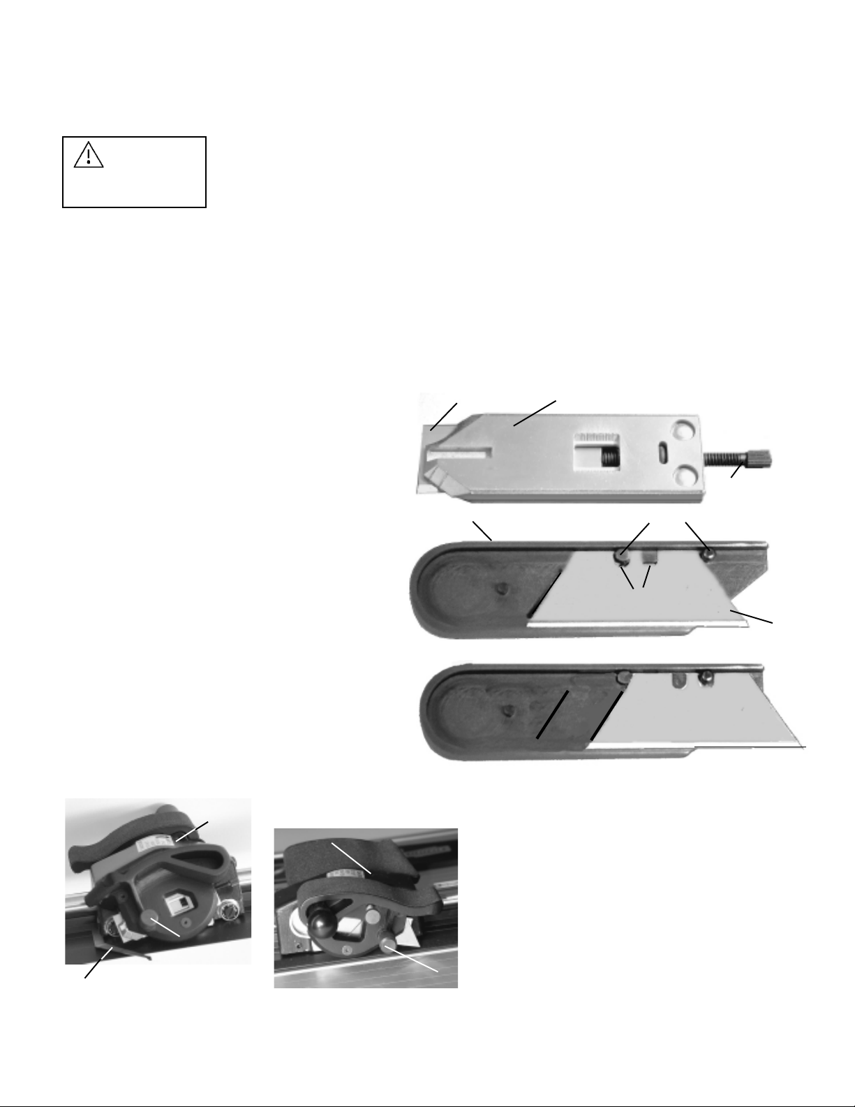
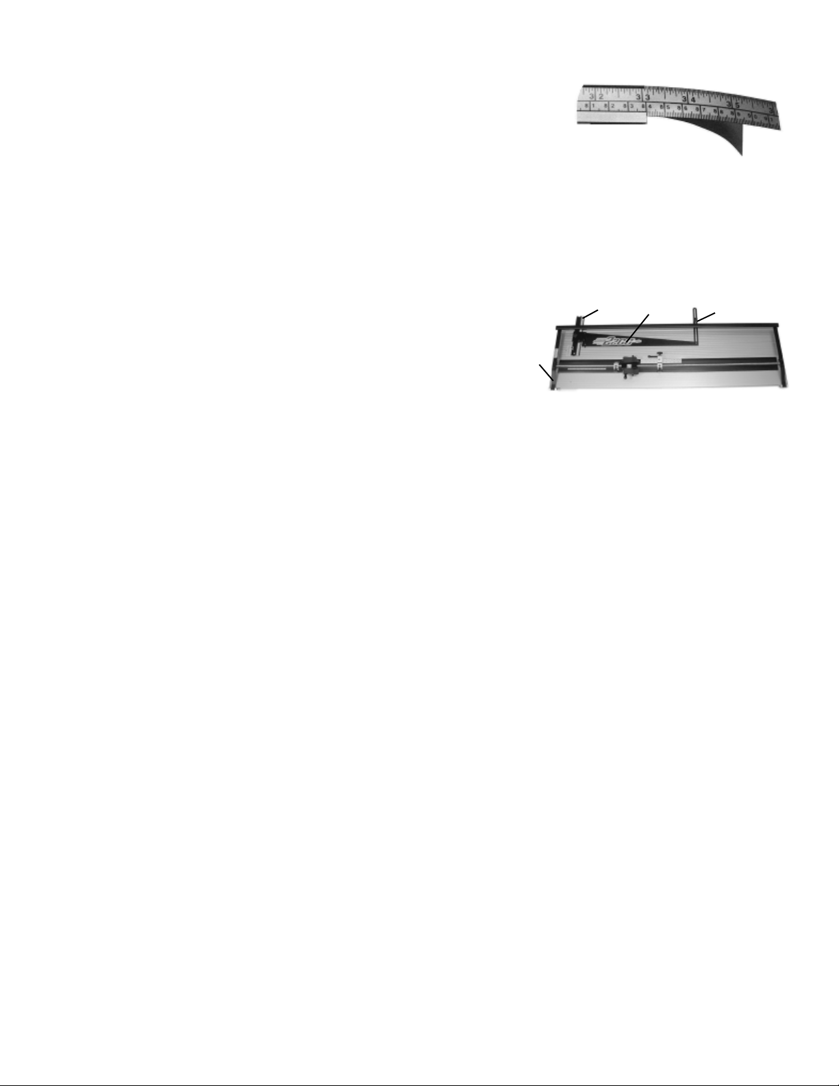
7. The scale in the Right Squaring Arm has pressure sensitive adhesive on the underside. Slide the scale out to the
right several inches. Peel off 4" of the protective paper from the adhesive and
slide the scale back to the left, but do not set the adhesive yet. See Figure 14.
8. Dra a vertical line 3" from the left edge of a mat. Place the mat’s lo er edge
against the Right Squaring Arm and slide it slo ly to the left until it contacts
the vertical blade (sizing blade) hich should be rotated do n ard. The scale
should no be positioned in its slide aligning the pencil mark ith the 3" index
on the scale. Press do n on the right end of the scale so it adheres to the Right Squaring Arm. If it should ever be
necessary to reposition this scale, it should ill be easy to pry up the adhered section and relocate the scale.
Figure 14
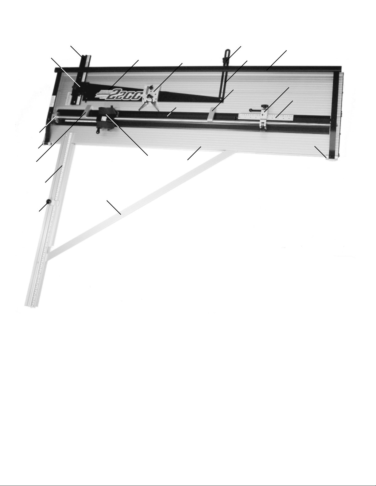
1. Remove the Mat Guide (A), Mat Guide Slide (B) and the Bracket (C) on the left side of the Base. Set the fasteners
aside to be used again.
2. Remove both End Caps (D) from the machine and save. Set the scre s
aside to be used again.
3. Three sets of scre s and square nuts are provided. Only t o sets ill be
required for 40” and 48” models. Insert button head scre s through the
holes on the left edge of the Base ith the threads sticking out. Scre
the square nuts on the scre s only one or t o turns. They must be very loose for no .
4. Slide the optional Base Extension on the nuts. You ill note the square nuts fit in a groove on the the right side
of the Base Extension. Align both ends of the base members and tighten the scre s and square nuts. You ill use
the hex rench supplied ith the machine.
5. Assemble the ne End Caps using the scre s from the discarded ones and additional scre s from the parts bag.
Attach the three rubber buttons from the parts bag to the bottom ribs of the Base Extension.
6. Install the ne , longer Mat Guide Slide on the Base, using the fasteners from the old one. Slide the Mat Guide on
the Mat Guide Slide and reinstall the Bracket on the left edge of the Base Extension. Square the machine as
sho n in the adjustments section of this O ner’s Manual.
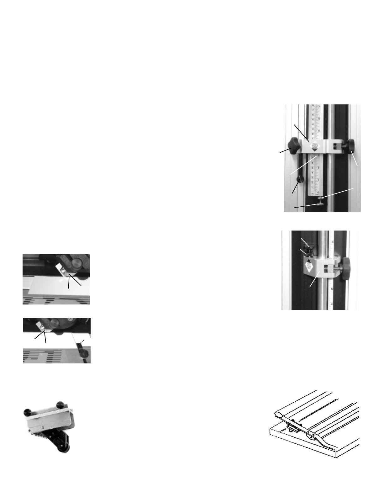
7. A ne , longer Upper Measuring Stop Slide is provided in case you are using the Measuring Stop option. Simply
exchange it on the Upper Measuring Stop. Also, longer inch and metric scales are provided in this kit to replace
those on top of the Mat Clamp to permit you to set the Lower Measuring Stop to larger mat border dimensions.
If you ish to install these ne scales, mark the Mat Clamp at the zero position before removing the old scale. In this
ay you can easily locate the ne scale.
8. The ne Base Extension has a tapped hole in line ith the Mat Guide Locking Strap. You may ish to mount the
Upper Locking Knob on top of the Base Extension. This ill accommodate the same mat border dimensions as
the standard machine. When larger mat borders are required, the Upper Locking Knob can be moved to the
Bracket on the left side of the Base Extension.
BASE EXTE SIO
Figure 15
A
BC
D
63
BRAZO E ESCUADRA
Esta opción acelerará la velocidad de producción de passe-partout al brindarle una reducción exacta de la tabla del passe-partout. Su
construcción maciza y abrazadora le asegurará medidas exactas y ángulos de 90 grados, tan importantes para un buen trabajo con
passe-partout.
Herramientas necesarias: destornillador Phillips, llave hexagonal de 5/32", y una llave ajustable. Recibirá las piezas del Brazo en
escuadra desmontadas en tres partes, el Brazo en escuadra (A) con escala en pulgadas o decimal, la Abrazadera en ángulo (B),
una Parada del brazo en escuadra (C) y los sujetadores. Vea la Figura 12.
1. La Fletcher 2200 debería reposar sobre una superficie lo suficientemente
amplia y plana como para brindar apoyo al Brazo en escuadra. Verá un orificio
en la Base aprox. 5" del final más cercano (D). Monte el tornillo de cabeza
plana, que se encuentra en la bolsa de piezas, a través del Brazo
en escuadra y la Base. Coloque la arandela, la arandela gro er y la
tuerca hexagonal en el tornillo debajo de la Base y ajústelas.
2. Sobre el borde derecho de la Base aprox. a unas 40" del final más cercano,
encontrará un tornillo de cabeza cilíndrica (E) que se introduce en una tuerca
de la Base. Quite el tornillo con la llave hexagonal de 5/32". Deje la tuerca en la
Base. Sobre el final superior de la Abrazadera en ángulo, verá un orificio en
un soporte. Conecte este soporte con el borde de la Base utilizando este
tornillo y esta tuerca. Ajuste suavemente sólo el tornillo.
3. Quite el tornillo de cabeza plana y tuerca hexagonal excéntrica de la bolsa
de piezas. Monte este tornillo y la tuerca excéntrica a través del Brazo en
escuadra y el orificio al final de la Abrazadera en ángulo (F). Asegúrese de
que la tuerca esté bien colocada sobre el orificio de 7/16" en la Abrazadera
en ángulo. Déjela ligeramente suelta.
4. Gire con los dedos la tuerca hexagonal. Notará que el Brazo en escuadra se mueve hacia arriba y abajo con respecto
a la Abrazadera en ángulo. Aproximadamente a la mitad de este movimiento, ajuste el tornillo de cabeza plana mientras
sostiene la tuerca hexagonal.
5. La Guía de passe-partout debería ajustarse en la posición de
la Guía de deslizamiento. Coloque un passe-partout entero (de 32x40)
horizontalmente sobre la Base con el borde inferior reposando sobre el
Brazo en escuadra. Fíjese que no se coloca sobre la escala. Deslice el
passe-partout hacia la izquierda de tal manera que toque
la Guía de passe-partout por igual en toda la longitud de la Guía de
passe-partout. Notará que el passe-partout probablemente no está en
contacto con el Brazo en escuadra a todo lo largo. Deslice el final
superior de la Abrazadera en ángulo, bajo el tornillo de cabeza
cilíndrica hasta que el passe-partout esté en pleno contacto con la Guía
de passe-partout y el Brazo en escuadra. Vea la Figura 13.
6. Afloje suavemente el tornillo de cabeza plana en la unión del Brazo
en escuadra y la Abrazadera en ángulo. Mientras sostiene el tornillo
con el destornillador, haga girar la tuerca suavemente hasta que el
borde inferior del passe-partout esté en contacto en todo el largo con el
Brazo en escuadra y la Guía de passe-partout. Ahora, ajuste el
tornillo de cabeza plana sin dejar que la tuerca gire. También ajuste
la tuerca que está debajo de la Base al final del Brazo en escuadra
y el tornillo de cabeza cilíndrica que sostiene a la Abrazadera en
ángulo hacia el lado derecho de la Base. Si no logra obtener la
condición en escuadra con este ajuste, deslice la Abrazadera en
ángulo donde está sujeta con el tornillo de cabeza cilíndrica y repita
el ajuste con la tuerca excéntrica. Asegúrese de que todos los tornillos
estén bien ajustados y luego vuelva a verificar la escuadra trayendo el
passe-partout para hacer contacto con el Brazo en escuadra y la Guía
de passe-partout al mismo tiempo.
A
B
C
DE
F
Figura 12
Figura 13

11
A GLE MAT GUIDE
The Angle Mat Guide provides an indispensable addition to the Fletcher 2200. You can produce angled cuts over a
range of 15 degrees to 75 degrees. In addition to simple 45 degree corner cuts, a ide variety of multi-sided openings
can be produced easily and ith precision. No matter ho complex the opening, you can create double mats ith exact
and consistent liner exposures.
It is simple to attach the Angle Mat Guide to the Mat Guide on your Fletcher 2200. Refer to Figure 16. The Locking
Pin (a) can be placed in any of the three holes (b). Selecting the hole on the left ill locate the Angle Mat Guide at the
lo er end of the Mat Guide for smaller mats, up to 8" X 10" (200mm X 250mm). Using either of the next t o holes to the
right ill locate the tool to ard the upper end of the Mat Guide for large mats.
To attach, set the Angle Mat Guide on the Mat Guide and slide it do n ard until it stops. It ill locate on the right side of
the Mat Guide ith t o projections on the underside, and on the left ith the Locking Pin. While continuing to pull it
to ard you, turn the Locking Pin (a) counterclock ise to firmly lock the Angle Mat Guide in place. To remove it, turn the
Locking Pin clock ise.
1. Figure 16 illustrates a simple 45 degree corner cut opening in an 8" x 10" (200mm x 250mm) mat. Mark pencil lines
on the back of the mat in the conventional ay starting ith the Mat Guide set at 1-1/2" (38mm) as sho n by lines
labelled B.
2. Set both Angle Arms of the Angle Mat Guide at 45 degrees. Place a 90 degree drafting triangle bet een them hile
tightening the Angle Locking Knob (c). Use a corner of your mat instead of a triangle if it is accurately squared.
3. Set the Mat Guide for a
3" (76mm) border and
using the Clamp as a
straight edge, make
pencil marks on the
back of the mat as
sho n by lines (A).
4. No make the 4 cuts
(A), starting and stop-
ping at lines (B) to
control over cuts. Be
sure the corner of the
mat is ell seated
against both Angle
Arms during each cut.
5. Remove the Angle Mat
Guide, reposition the
Mat Guide to 1-1/2"
(38mm) and cut lines
(B), using the angle
cuts produced in step 4
to control over cutting.
DUST COVER
A dust cover is available for the Fletcher 2200. It is a practical and recommended option to maintain cleanliness and top
orking order of your mat cutter.
abA
A
B
B
B
B
c
Figure 16
A
A
62
OPCIO ES
PARADAS DE MEDIDA
Las Paradas de medida son más que una ayuda en la producción de passe-partout de medidas comunes. Se usan
rápidamente y eliminan la técnica de dibujar las líneas detrás del passe-partout que desperdicia tiempo. Además, aseguran
sobre cortes mínimos y evitan cortes demasiado pequeños. Los Tornillos de parada se ajustan de la siguiente manera y no necesitan
cambiarse a menos que se cambie la extensión de la cuchilla para distintos espesores de passe-partout.
1. Inserte el Gancho de ubicación para el ancho de borde deseado y coloque un passe-partout
debajo del Gancho en la posición general para corte biselado. PRECAUCIÓN: Asegúrese de que
el borde izquierdo inferior del passe-partout repose sobre la Parada de passe-partout ( ) según
se ve en la Figura 11. Haga cuatro marcas en lápiz según se describió anteriormente.
2. Establezca la Escala de medida superior (A) (Figura 8) al mismo ancho que el Gancho
de ubicación y trábela en su lugar con el Tirador B.
3. Deslice la Parada superior (D) hacia el passe-partout mientras se pulsa el Botón con
resorte (C) sobre la hoja. Cuando el Botón toque el borde superior del passe-partout,
trabe la Parada superior en la posición con su Tirador (E).
4. Mueva el Cabezal de corte contra el Tornillo de parada (F) sobre la Parada superior.
Haga girar la cuchilla de corte biselado hasta que toque el passe-partout. Debería tocar el passe-
partout aprox. a 1/8" (3 mm) sobre la línea en lápiz horizontal. Si no fuera así, gire el Tornillo de
parada hacia adentro o afuera hasta que la cuchilla esté en la posición correcta. Trabe el Tornillo
de parada en su lugar con la Contra tuerca (G).
5. Establezca la Parada inferior (H) sobre el mismo ancho de borde con la escala montada
sobre el Gancho. Vea la Figura 9. Empiece en la posición superior e inserte la cuchilla a través
del passe-partout. La línea escrita sobre la derecha de la Bandeja (L), en la Figura 10, debería
alinearse con la línea hecha en lápiz y la Mira debería alinearse con la línea en lápiz. Ahora, tire
del Cabezal de corte hacia la parada más baja de forma
normal. Debería tocar la parada más baja cuando la cuchilla
haya pasado la línea horizontal más baja, aprox. 1/8"
(3 mm). La línea escrita sobre la izquierda (M) de la Bandeja
debería alinearse con la línea hecha a lápiz, vea la Figura 11.
Si es necesario, ajuste el Tornillo de parada (J) en la parada
más baja para lograr una dimensión de 1/8" (3 mm). Trabe
el Tornillo de parada (J) en su lugar ajustando su
Contra tuerca (K).
6. Comience a cortar un passe-partout completo. Corte los lados
opuestos primero, luego mueva la parada superior hacia el final superior del passe-partout y corte
los otros dos lados. Observe los ángulos de los cortes biselados de la parte delantera.
La “caída” debe estar completamente suelta y los sobre cortes apenas visibles. Si no fuera así,
ajuste los Tornillos de parada. Demasiados sobre cortes requieren mover el Tornillo de parada
hacia el Cabezal de corte. Una separación de ángulo incompleta requiere mover el tornillo de
parada lejos del Cabezal. No es necesario volver a ajustar el tornillo de parada a menos que
se corten passe-partout de diferente espesor.
LEVA TADORES DE GA CHOS
DE PASSE-PARTOUT
Figura 8
A
B
C
D
E
G
F
H
J
K
Figura 9
Figura 10
L
M
Figura 11
Dos Levantadores de ganchos de passe-partout, (uno se ve a la
izquierda), se proveen como una opción. Cada uno se monta debajo
de un Soporte con bisagra con el rodillo a resorte sobre la Base según se
muestra a la derecha. Esto deja libres ambas manos para poder ubicar la hoja
y el passe-partout. Una leve presión sobre el Asa baja el Gancho
de passe-partout hacia el passe-partout.

12
ADJUSTME TS
SQUARE THE MAT GUIDE
1. Slide the Mat Guide to the right until it contacts the Locator Pin
(A) in the 2" (50mm) hole, and tighten the Lower (B), then Upper
Locking Knobs on the Mat Guide. See Figure 17.
2. Place an 8” x 10” matboard under the Clamp in full contact ith
the Mat Guide at the lo er part of the Mat Guide.
3. Make a bevel cut about 1” (25 mm) long near the lo er edge of
the mat. Move the mat to the top of the Mat Guide and make
another cut starting beyond the first cut and running into it. When
the Mat Guide is properly squared, these t o cuts ill coincide
and appear to be a single cut.
4. If the t o cuts are not in line, the Mat Guide must be squared as
follo s: Loosen the left-hand (C) and right-hand (D) scre s on the
Mat Guide Slide (E). Loosen both the Lower Locking Knob (B) and Upper Locking Knobs (F). Place the t o
Squaring Fixtures (G) (from the parts bag) on the steel Shaft, one near the bottom end of the Mat Guide and the
other near the top, as in Figure 18. Remove the
Locator Pin (A) and use your left hand to slide
the Mat Guide firmly against both Squaring
Fixtures. While keeping pressure against the
Squaring Fixtures tighten the Lower Locking
Knob (B) then the left hand scre (C), follo ed
by the right hand scre (D) on the Mat Guide
Slide (E). Be sure to leave the Upper Locking
Knob (F) loose during this adjustment. Retest
for squareness as in item 3 above.
5. Al ays tighten the Lower Mat Guide Locking Knob (B) before the Upper Locking Knob (F). It is the lo er one
hich aligns the Mat Guide. The upper one simply anchors the upper end of the Mat Guide.
6. Make a bevel cut and measure its distance from the left side of the mat. If it is not exactly 2” (50mm), turn the hex
scre (H) clock ise to decrease or counterclock ise to increase the mat border. Then, re-position the Index (J) to
read 2” (50mm) on the scale.
CUTTI G HEAD ADJUSTME TS
Figure 17
B
C
D
F
G
Figure 18
Figure 20
L
1. Periodically adjust the Cutting Head to assure a
close fit on the Shaft. Slo ly tighten either of the
set scre s (K) hile sliding the Cutting Head back
and forth on the Shaft. When you feel a drag,
loosen the scre until the Cutting Head slides
freely. Repeat ith the other set scre (K).
2. Adjust set scre (L) in the same manner. Be sure to slide the Cutting Head
hile tightening the set scre so you do not over-tighten and cause damage.
K
Figure 19
A
D
EH
J
G
61
RA URA E V
Si desea agregar una ranura en V, antes de cortar la abertura de la página 6, siga este procedimiento.
1. PRECAUCIÓ : Afloje la Parada de passe-partout y deslícela hacia la izquierda para que no sobresalga de la Guía de
passe-partout. Re-ajuste el Tirador que traba. Quite el Gancho de ubicación, afloje los dos Tiradores que traban la guía y
deslice la Guía de passe-partout toda hacia la derecha en contra del GA CHO. Coloque el Gancho de ubicación en el orificio
más cercano al tornillo hexagonal del lado izquierdo de la Base de la guía de passe-partout y deslícela nuevamente hacia la
izquierda para que el tornillo hexagonal repose sobre el Gancho de ubicación. Ajuste los Tiradores que traban la guía. Esta
instrucción se aplica a ambos sistemas de medidas.
2. Remover la Mira (H). Coloque la “caída”, derecha, contra la Guía de passe-partout. Comience con el Cabezal de corte bien
sobre el borde superior del passe-partout. Haga girar el pivote del filo bisel y tire de él a una velocidad estable hasta que haya
recortado las salientes del filo de la “caída”. Repita este procedimiento en los tres bordes. Quite los desechos después de cada
corte para evitar interferencias cuando se coloca el passe-partout contra la Guía. Si la cuchilla se proyecta demasiado lejos de la
bandeja, puede tocar la Guía y eso dañará a la cuchilla.
3. Coloque la “caída” al revés sobre una superficie plana de la mesa. Coloque el passe-partout sobre la “caída”, según se la orientó
en el paso 3 de la página anterior. Coloque cinta en los cuatro cortes. Gire el passe-partout y verifique la ranura en V.
4. Quite el Gancho de ubicación, afloje los Tiradores que traban la guía, deslice la Guía hacia la izquierda e inserte el Gancho
de ubicación en el cuarto orificio de la derecha, el de 3" (70 mm). Deslice la Guía contra el Gancho de ubicación y ajuste sus
dos tiradores.
5. Empiece a cortar las aberturas según se describe en los pasos 4 y 5 en la página anterior. El resultado será un passe-partout con
una ranura en V de 1/2" (10 mm) afuera y una abertura de 3" (70 mm) de borde.
6. El ancho de la ranura en V puede ajustarse levemente, girando el tornillo hexagonal del lado izquierdo sobre la base de la
Guía con una llave hexagonal que se encuentra en la bolsa de piezas. Al girar el tornillo en el sentido del reloj, aumentará el
ancho de la ranura en V, pero aumentarlo demasiado causará que la cuchilla lo corte todo a lo largo del passe-partout y se
obtendrá una brecha, no una ranura. Al girar el tornillo en el sentido contrario a las agujas del reloj, disminuirá el ancho de
la ranura en V. Si se ajusta demasiado en este sentido, causará que la cuchilla golpee la Guía de passe-partout.
PASSE-PARTOUT DOBLE
Un Passe-partout doble con una ranura en V es muy atractivo, popular y fácil de hacer con el sistema profesional de corte
Fletcher 2200.
1. Prepare un passe-partout de color contrastante para que se convierta en el forro. Hágalo 1/8" (3 mm) menos de ancho
y largo que el passe-partout que utilizó en el ejemplo anterior.
2. Coloque la “caída” que produjo en el paso 5 anterior al revés en una superficie limpia y plana. Coloque el passe-partout
con ranura en V sobre ésta para que la “caída” entre en la abertura. Utilizando un colocador de cinta, coloque una o dos tiras
de cinta adhesiva en los cuatro bordes del passe-partout. Coloque dos tiras de cinta adhesiva sobre la “caída”, pero alejadas de
los bordes. Coloque la cara del passe-partout forro con la faz hacia abajo sobre el primer passe-partout. Asegúrese de
que los cuatro bordes estén dentro de los bordes del passe-partout superior. El montaje está todo pegado de forma conjunta.
3. El Medidor de passe-partout aumentará el ajuste de la Guía cuando el Gancho de ubicación se coloque a través del Medidor
de passe-partout luego la Guía de deslizamiento. Coloque el Gancho de ubicación a través del Medidor de passe-partout y
en el orificio de 3" (70 mm) como se hizo anteriormente. Notará que el Medidor de passe-partout puede girarse. Gírelo de tal
forma que el lado marcado con 3/16" (5 mm) quede a la izquierda. Mueva la Guía hasta hacer contacto con el Medidor de passe-
partout y ajuste los Tiradores que traban.
4. Coloque los passe-partout montados al revés debajo del Gancho y contra la Guía y la Parada. Haga cuatro líneas en lápiz como
cuando hizo el primer passe-partout. Proceda a cortar los cuatro bordes como lo hizo anteriormente.
5. Ahora se descarta la doble “caída” y obtiene un Passe-partout doble con ranura en V. Fíjese que el passe-partout forro expuesto
es 3/16" (5 mm) más ancho y uniforme en los cuatro bordes.

13
MAI TE A CE
Maintenance of your FLETCHER 2200 PROFESSIONAL MAT CUTTER is mostly a matter of cleanliness.
1. Keep a dry, lint free cloth near the machine. Wipe the Shaft and Mat Clamp daily and frequently during use to
remove loose paper particles, dust, and other foreign matter. DO NOT USE OIL OR WAX. Cover the machine ith a
dust cover hen not in use.
2. Periodically check the squareness and accuracy of sizing cuts, Mat Guide squareness and dimensions of mat bor-
ders. If corrections are required, follo the procedures outlined in the ADJUSTME TS section. The frequency of
inspection depends upon ho many people are using the cutter and the care it is given. If set up properly and the
mounting and adjustment scre s are not changed, it ill produce excellent results indefinitely.
3. If the Cutting Head makes a rumbling noise it is caused by paper debris on the Mat Clamp or Ball Bearings.
First, ipe the top of the Mat Clamp thoroughly. Slightly loosen the set scre (L) sho n on the previous page in
Figure 20. Tack do n one end of a 6" strip of tape on the top of the Mat Clamp in the path of the Roller Bearing and
fold the tape back a ay from the Cutting Head so the glue side of the tape is facing up. Slo ly slide the Cutting
Head over the tape. Debris ill be transferred to the tape hich can be discarded. Repeat this procedure for the other
Ball Bearing track. Be sure to re-adjust the set scre (L) as described on the prior page.
4. Both the bevel and straight pivot heads on the Cutting Head should rotate freely, but ithout excessive play. The
Pivot Screw, accessible after removing the Magazines, must be tight. Shim Washers are available in four different
thicknesses from .002” to .006” (.051mm to .152mm). Choose a combination of shims and insert the Pivot Screw
through them before tightening. These ashers are identified as Ref. number 5 in the Cutting Head Parts List.
5. If it is ever necessary to remove the Cutting Head, follo this procedure:
a. Remove both blade Magazines. Remove the hex head bolt (A) from the lo er end of the Shaft. Be sure to keep
the spring asher ith the bolt. See Figure 21.
b. Remove the t o button head hex scre s (B) from the lo er Hinge Bracket using the hex rench provided.
c. Slip the Shaft Bracket off the Shaft. Lift the Clamp Handle just enough to allo the Shaft Bracket to be
removed.
d. Slide the Cutting Head off the shaft. Do not lift the Clamp Handle any higher than clearance requires. Hold your
hand beneath the Cutting Head to prevent the Ball Bearing (C) from falling to the floor. Re-assemble the
Cutting Head in the reverse order.
A
B
C
Figure 21
Figure 22
60
ABERTURA SIMPLE
El requisito más importante para cortar passe-partout es una cuchilla afilada. El passe-partout es un producto abrasivo
e irá gastando la cuchilla. El valor de passe-partout bien cortado es mucho mayor que el coste de una cuchilla.
1. Prepare una hoja de aprox. 8" (200 mm) de ancho y 40" (1.016 mm) de largo
y colóquela debajo del Gancho (A). Use un trozo de passe-partout
del mismo espesor que el que cortará y colóquelo sobre la hoja. Presione
sobre el Asa suavemente para sostener el passe-partout en su lugar. Deslice
el Cabezal de corte (B) sobre el borde del passe-partout y
haga girar el Pivote para insertar la cuchilla sobre la hoja. Ahora, puede
observar la punta de la cuchilla dentro del 1/3 del espesor de la hoja. Passe-
partout de distintos espesores exigen volver a probar y ajustar la extensión
de la cuchilla. Si presiona sobre el Asa con demasiada fuerza,
el Gancho se inclinará hacia arriba en el centro. Esto aumentará la distancia
entre la punta de la cuchilla y el passe-partout en el medio
del corte y la cuchilla no podrá penetrar totalmente cuando se corte un
passe-partout grande. Utilice sólo la presión suficiente como para trabar
el passe-partout en su lugar y evitar que se mueva. Vea la Figura 5.
2. El Gancho de ubicación (C) brinda ajustes establecidos, exactos y repetibles para los bordes del passe-partout desde
1-1/2" a 8" con aumentos de 1/2" para el sistema inglés. El Medidor de passe-partout agrega 1/8",
3/16", 1/4" ó 5/16 a las posiciones del Gancho de ubicación. El Gancho de ubicación tiene orificios para
los bordes del passe-partout que van de los 30 mm a 210 mm con incrementos de 10 mm. El Medidor de
passe-partout agrega 3 mm, 4 mm, 5 mm, ó 7 mm al ajuste del Gancho de ubicación. La posibilidad de
repetir ajustes exactos es una ventaja a tener que leer una escala, especialmente cuando se producen
varios passe-partout.
3. Por ejemplo, corte un passe-partout simple con un borde de 3" (70 mm) y uno con ranura en V a 2-1/2" (60 mm). Coloque
el Gancho de ubicación en el tercero orificio del lado derecho en la Guía de deslizamiento (D) y deslice la Guía (F) hacia la
derecha hasta ubicar al Gancho de ubicación. Ajuste ambos Tiradores de la guía (E) el inferior y el superior como se muestra
en el núm. 7 en la página 4. Siempre ajústelas en la misma secuencia, primero la inferior antes que la superior. Coloque un passe-
partout pre-medido de 16" X 20" (400 mm X 500 mm) al revés y deslícelo hacia la izquierda en contra de la Guía y hacia abajo en
contra de la Parada (G). Baje el Asa del gancho. Use un lápiz afilado, nunca con tinta, y dibuje una línea a lo largo
del borde izquierdo del Gancho comenzando y parando cada
1/2" (13 mm) desde el borde del passe-partout. Haga girar el
passe-partout 90 grados y repita el dibujo en lápiz hasta
que se hayan dibujado los cuatro lados. También dibuje
con lápiz donde se “caerá” el borde para poder mantener
la orientación cuando se realice la ranura en V o cuando
se corten passe-partout dobles.
4. Presione sobre el Asa del gancho y gire el filo bisel de
la cuchilla en passe-partout para comenzar con el corte.
La Figura 6 muestra la posición de comienzo del corte
uniendo la Mira (H) con la línea superior del lápiz (K).
5. Haga el corte, deténgase cuando la Mira (H) llegue a la
línea más baja del lápiz (L). Esto es el final del corte como
lo muestra la Figura 7.
6. Levante el asa, haga girar el passe-partout 90 grados y repita el próximo corte, comenzando y deteniéndose en el cruce de las
líneas en lápiz como anteriormente. Quite el passe-partout y examine el lado superior. Debería haber un sobre corte perceptible
en cada esquina para asegurarse que la “caída” esté libre del passe-partout. Los sobre
cortes deben corregirse a su juicio, alineando la Mira con las líneas en lápiz y con
la extensión de la cuchilla.
FFigura 6
AAAA
Figura 7
CÓMO CORTAR PASSE-PARTOUT
A
B
C
D
E
F
G
Figura 5
H
K
L
H
G
1
4
1
8
3
16
5
16

14
TROUBLESHOOTI G GUIDE
PROBLEM POSSIBLE CAUSE CORRECTIO REFERE CE
Frayed bevel cuts Dull blade Change to a ne blade SET UP
Worn out slip sheet Use fresh slip sheet HOW TO CUT MATS
Not cutting Blade projection Extend projection SET UP
through the mat of blade
Worn or broken blade Replace blade SET UP
Pressing too hard on Ease up on pressure HOW TO CUT MATS
the handle
Excessive overcut Blade projection Adjust projection SET UP
of blade
Measuring Stop Adjust Measuring Stop HOW TO CUT MATS
Undercut Blade projection Adjust projection SET UP
of blade
Measuring Stop Adjust Measuring Stop HOW TO CUT MATS
Head binds Head Bearings Adjust Head Bearings MAINTENANCE
Head too loose Head Bearings Adjust Head Bearings MAINTENANCE
“Hook” in cuts Blade projects too far Adjust projection SET UP
of blade
Head loose Adjust Head Bearings MAINTENANCE
Head “rumbles” Roller Bearing path dirty Clean Mat Clamp MAINTENANCE
Roller Bearings dirty Remove Head and MAINTENANCE
clean Bearings
Use tape to remove MAINTENANCE
foreign material
FOR ASSISTANCE, CONTACT THE FLETCHER-TERRY COMPANY CUSTOMER SERVICE DEPARTMENT AT
800.843.3826 (U.S./CANADA) OR customerservice@fletcher-terry.com.
59
CUCHILLAS
El lado de corte bisel del Cabezal de corte acepta cualquiera de las tres distintas cuchillas Fletcher. La 05-012 tiene un
espesor de 0,012" (0,3 mm) y se utiliza para cortar superficies regulares. La 05-015 tiene un espesor de 0,015" (0,4 mm) y se utiliza
para superficies más gruesas y densas. La 05-016 es una cuchilla de filo simple, biselada en un solo lado. Se utiliza para cortar
superficies muy densas o gruesas y debe instalarse con el filo biselado alejado del cabezal.
El filo derecho que se encuentra a la derecha es la Cuchilla de servicio, 05-004, y puede cortar material de un espesor de 1/2"
(12 mm). Todas las cuchillas excepto la 05-016 pueden colocarse hacia atrás en la bandeja para duplicar la vida útil, no obstante,
deben insertarse con mucho cuidado para evitar daños.
1. Coloque una Cuchilla (C) en la Bandeja de corte
bisel (A) como se muestra en la Figura 1. El Tornillo
de extensión de la cuchilla (B) debería ajustarse
de tal forma que la Cuchilla (C) penetre cerca de
1/3 del espesor de una hoja colocada debajo de la
superficie a cortar. La cuchilla siempre debe reposar
contra el Tornillo de extensión de la cuchilla (B), y
la Bandeja (A) debe estar insertada completamente
dentro del Cabezal de corte (D). Ajuste el Tirador
que traba (E) firmemente. Vea la Figura 3.
2. El corte derecho se realiza sobre el lado derecho
del Cabezal de corte (D). La Bandeja (F) y la Cuchilla
de corte (G), (05-004), se ven en la Figura 2. Hay 4
posiciones de profundidad para esta cuchilla, pero sólo
se utilizan dos, según lo muestran las Figuras 2 y 2a. La
Figura 2a es la posición para un material de 1/2"
(12 mm), mientras que la Figura 2 es para superficies
de 2, 4, 6, y 8 capas. La cuchilla se mantiene en su lugar
por un imán. Coloque la Bandeja (F) en una parada en
el Cabezal de corte (D) y ajústela con el Tirador que
traba (K). Vea la Figura 4.
3. La Mira (L) que se ve en la Figura 3 se usa
para controlar el comienzo y fin de un corte
cuando se utilizan líneas en lápiz dibujadas
detrás del passe-partout. Se mantiene en su
lugar en el Cabezal de corte con un imán que
se puede quitar cuando no se utiliza. El uso
de esta característica se explica en las
páginas siguientes.
PRECAUCIÓ :
MO TAJE
Coloque los nueve amortiguadores de goma auto adhesivos que están en la bolsa de piezas, de forma equilibrada sobre la
parte de abajo de la Base para evitar que se raye la mesa. Coloque la Fletcher 2200 sobre una mesa con el Asa del gancho
hacia la izquierda.
Figura 1
A
Figura 2a
F
H
E
J
C
D
Figura 3
Figura 4
B
MANEJE LAS CUCHILLAS
CON MUCHO CUIDADO.
SON MUY AFILADAS
G
K
L
Figura 2
D

15
PARTS LISTS
32 12-041 End Cap 2
33 12-042 Mat Stop Knob 1
34 12-043 Washer 1
35 12-044 Mat Stop 1
36 12-244 Flat Head Scre 2
37 12-576 Comfort Knob 2
38 12-514 Key 1
39 12-049 Stop Scre 2
40 12-052 Wear Tape 5
41 12-053 Square Nut 9
42 12-054 End Cap Scre 20
43 12-056 Button Head Scre 4
44 12-318 Washer 1
45 12-125 Bracket 1
46 12-126 Flat Head Machine Scre 1
47 12-127 Lock Washer 1
48 12-128 Acorn Nut 1
49 12-543 Mat Guide Squaring Fixture 2
Ref. Part o. Description Quantity
1 12-500 Base R.H. 40" Capacity 1
1 12-001 Bass R.H. 48" Capacity 1
1 12-116 Base R.H. 60" Capacity 1
2 12-501 Base L.H. 40" Capacity 1
2 12-502 Base L.H. 48" Capacity 1
2 12-503 Base L.H. 60" Capacity 1
3 12-504 Mat Guide Slide Inch 1
3 12-554 Mat Guide Slide Metric 1
4 12-567 Mat Guide Slide Scale 1
5 12-583 Mat Guide Assy. 40” & 48” 1
5 12-584 Mat Guide Assy. 60" Capacity 1
6 12-507 Locking Strap 1
7 12-585 Handle 40" Capacity 1
7 12-568 Handle 48" Capacity 1
7 12-580 Handle 60" Capacity 1
8 12-569 Handle End Cap 2
9 12-570 Hinge Bracket 2
10 12-009 Hinge 2
11 12-010 Pivot Shaft 2
12 12-011 Shaft Bracket 2
13 12-012 Shoulder Scre 2
14 12-013 Spring Washer 2
15 12-014 Locator Pin 2
16 12-015 Mat Gage Imperial 1
16 12-550 Mat Gage Metric 1
17 12-509 Base Nut 2
18 12-586 Cutting Head Assembly 1
19 12-511 Clamp Assy. 40” 1
19 12-512 Clamp Assy. 48” 1
19 12-513 Clamp Assy. 60” 1
20 12-314 Button Head Scre 9
21 12-314 Button Head Scre 1
22 12-021 Button Head Cap Scre 6
23 12-022 Washer 2
24 12-023 Lock Nut 2
25 12-312 Flat Head Scre 1
26 12-571 Washer (Black) 1
27 12-573 Inch Scale 1
28 12-574 Metric Scale 1
29 12-035 Button 12
30 12-039 Scale Indicator 1
31 12-293 Pan Head Scre 1
Ref. Part o. Description Quantity
13-14
18
27
28
1
5
20
2
7
6
37-44
46-47
48 49
40
33-
34
35
36
25-
17
3
19
39
37-38
8
30-31
29
41
20
10
22
4
17
21-26
45
20 41
37-44
42 32
12
11
9
15 16
7
22-23
24 29
41
43 20
58
PIEZAS
1
2
4
5
6
78
9
10
11
9
12
15
16
13
14
17
17
1 Base
2 Guía de passe-partout
3 Asambly Gancho
4 Cabezal de corte
5 Asa del gancho
6 Tirador que traba la guía inferior
del passe-partout
7 Tirador que traba la guía superior
del passe-partout
8 Guía de deslizamiento del passe-partout
9 Pivote con bisagras
10 Correa
11 Parada medida superior
12 Parada medida inferior
13 Escala de parada superior
14 Brazo en escuadra
15 Parada del brazo en escuadra
16 Abrazadera del brazo en escuadra
17 Piezas para encuadrar
18 Guía de passe-partout con ángulos
3
18

16
Ref. Part o. Description Quantity
1 12-101 Angle Brace Assy. 1
2 12-099 Angle Brace Bracket 1
3 12-020 Pan Head Mach. Scre 2
4 12-027 Hex Nut 3
5 24-129 Lock Washer 3
6 24-130 Washer 3
7 12-098 Angle Brace 1
8 12-106 Squaring Arm Assy. 1
9 12-102 Squaring Arm 1
10 12-103 Mat Support 1
11 12-578 Scale 1
12 12-024 Flat Head Mach. Scre 2
13 12-016 Eccentric Nut 1
14 12-056 Button Head Cap Scre 1
15 12-516 Squaring Arm Stop 1
16 12-350 Plastic Knob 1
17 12-514 Key 1
CUTTI G HEAD
Ref. Part o. Description Quantity Ref. Part o. Description Quantity
1 12-572 Pivot Head Assembly (LH) 1 10 12-537 Shoulder Scre 2
2 12-530 Extension Spring 2 11 12-538 Bushing 2
3 12-588 Stainless Washer 2 12 12-591 Pivot Head Assembly (RH) 1
4 12-532 Pivot Scre 2 13 12-915 Knob (RH) 1
5 12-533 Shim Washer 4 14 12-542 Magazine Assembly (LH) 1
6 12-589 Comfort Grip (LH) 1 15 12-102 Pivot Arm 1
7 12-535 Knob (LH) 1 16 12-593 Magazine Assembly (RH) 1
8 12-590 Flat Head Cap Scre 5 17 12-241 Plastic Knob (RH) 1
9 12-073 Ball Bearing 3 18 12-242 Hex Stud 1
19 12-243 Sight Gage 1
20 12-592 Comfort Grip (RH) 1
RIGHT SQUARI G ARM
1
2
3
4, 5, 6
7
8
910
11
12
13
14
15, 16, 17
12
4, 5, 6
19
2
20
4, 5
7
9
10
11
12
13
16
8
14
16
17, 18
A
A
Section A-A
15
57
I TRODUCCIÓ
La cortadora profesional Fletcher 2200™ fue diseñada con el enmarcador profesional en mente y ha evolucionado desde los
conceptos probados de Fletcher 2000® y Fletcher 2100® e incorpora muchas sugerencias de los usuarios de productos de enmarcado
Fletcher-Terry. Se ha prestado especial atención al diseño ergonómico para brindar comodidad y facilitar su uso.
La Fletcher 2200 está disponible tanto en el sistema inglés (40", 48" y 60") como el métrico (1,0 m, 1,2 m y 1,5 m).
El Cabezal de corte incorpora cortes en bisel y derecho con un diseño cómodo en ambos pivotes. El lado que corta derecho utiliza
una cuchilla y una bandeja que cortan materiales como una plancha de espuma y gatorfoam® hasta un espesor nominal de 1/2" (12
mm). Ambas bandejas permiten el cambio de cuchillas lejos del Cabezal de corte minimizando la exposición al peligro de las cuchillas
afiladas. Una exclusiva Mira sobre el Cabezal de corte proporciona control preciso del corte cuando se utilizan líneas en lápiz en el
reverso del passe-partout.
El Cabezal de corte está instalado sobre un Eje pulido para minimizar el desgaste y el “enganche”. Se pueden realizar ajustes
para permitir que el enmarcador mantenga la precisión, a pesar del alto uso.
La gran utilidad del Gancho de ubicación se ha mejorado agregándole orificios a la Guía de deslizamiento de passe-partout
para brindar bordes de 1-1/2" a 8" en incrementos de 1/2" y de 30 mm a 210 mm en incrementos de 10 mm.
Una de las opciones incluye: Paradas de medida que aseguran mínimos cortes en exceso o en defecto; Levantadores de ganchos
que permiten que ambas manos estén libres para colocar la superficie en la posición adecuada; el Brazo en escuadra que se ajusta a
la base y brinda de forma rígida y correcta la medida de las superficies; la Guía de passe-partout con ángulos
que se ajusta a la Guía de passe-partout creando un medio para cortar ángulos distintos a 90 grados y la extensión de la placa
de base que permite bordes superiores a 16" (405 mm).
Varios passe-partout, con ranuras en V y otros diseños creativos se pueden producir fácilmente con la Fletcher 2200.
Garantía del producto
La compañía Fletcher-Terry garantiza que la máquina no tiene defectos en piezas ni mano de obra durante
dos (2) años a partir del día de compra. La compañía Fletcher-Terry garantiza que reparará o reemplazará
cualquier pieza defectuosa de la máquina siempre que la máquina se haya utilizado de forma normal con el
mantenimiento correspondiente y que el envío de la máquina o pieza defectuosa
a Fletcher-Terry esté a cargo del comprador. La compañía Fletcher-Terry deberá autorizar la devolución por
escrito. Se deberá entregar la prueba de compra para validar la cobertura de la garantía.
La garantía está en lugar de otros acuerdos y garantías expresos o implícitos. LA COMPAÑÍA
FLETCHER-TERRY EXPRESA POR LA PRESENTE SU DESCARGO SOBRE CUALQUIER OTRA
GARANTÍA O COMERCIALIZACIÓN AJUSTADO A UN DETERMINADO PROPÓSITO. La compañía
Fletcher-Terry no autoriza a ningún empleado ni representante a asumir ninguna otra responsabilidad que la
que esté expresada en la garantía del producto. La compañía Fletcher-Terry no se hace responsable de
ningún daño o pérdida, ya sea accidental o como consecuencia del uso o abuso indirecto de esta máquina.
En cualquier caso, el remedio único y exclusivo para el comprador, de acuerdo con esta u otra garantía, se
limita a la devolución del precio de compra pagado para esta máquina.
Fletcher 2200

17
BASE EXTE SIO
Ref. Part o Description Quantity
1 12-579 Scale/Mat Guide Slide 1
2 12-581 Scale (Inch) 1
3 12-582 Scale (Metric) 1
4 12-509 Base Nut 2
5 12-520 Mat Guide Slide 1
5 12-555 Mat Guide Slide (Metric) 1
6 12-130 Threaded Insert 1
7 12-132 Upper Stop Slide/Long 1
8 12-056 Button Head Scre 2
9 12-053 Square Nut 2
10 12-035 Button 3
11 12-131 Hex Nut 1
12 12-054 End Cap Scre 10
13 12-109 End Cap 2
14 12-020 Scre 1
15 12-024 Flat Head Scre 1
16 12-594 Base Plate 40” 1
16 12-595 Base Plate 48” 1
16 12-596 Base Plate 60” 1
1
2
3
4
5
6
7
8
9
10
11
12
13
14
15
MEASURI G STOPS
Ref. Part o. Description Quantity
1 12-556 Lo er Measuring Stop Assembly 1
2 12-084 Knurled Lock Nut 2
3 12-521 Stop Scre Assembly 2
4 12-523 Clamp Bar 2
5 12-524 Grooved Pin 2
6 12-557 Upper Measuring Stop Assembly 1
7 12-095 Shoe 1
8 12-573 Scale (Inch) 1
9 12-574 Scale (Metric) 1
10 12-525 Nylon Tubing 4
11 12-597 Knob 3
12 12-527 Upper Stop Slide 1
13 12-598 Spring Button Assembly 1
16
1
2
3
4
5
6
7
8
9
10
11
2
3
4
5
11
11
12
13
56
I TRODUCCIÓ 57
GARA TÍA 57
PIEZAS 58
MO TAJE 59
CUCHILLAS 59
CÓMO CORTAR PASSE-PARTOUT 60
ABERTURA SIMPLE 60
RA URA E V 61
PASSE-PARTOUT DOBLE 61
OPCIO ES 62
PARADAS DE MEDIDA 62
LEVA TADORES DE GA CHOS
DE PASSE-PARTOUT 62
BRAZO E ESCUADRA 63
EXTE SIÓ DE LA BASE 64
GUÍA DE PASSE-PARTOUT CO Á GULOS 65
CUBIERTA CO TRA EL POLVO 65
AJUSTES 66
COLOQUE E ESCUADRA LA GUÍA
DEL PASSE-PARTOUT 66
AJUSTES DEL CABEZAL DE CORTE 66
MA TE IMIE TO 67
GUÍA DE SOLUCIÓ DE PROBLEMAS 68
LISTADO DE PIEZAS 69
Í DICE

18
1 12-136 Housing 1
2 12-137 Disc 2
3 12-138 Angle Arm-Upper 1
4 12-139 Angle Arm-Lo er 1
5 12-140 Angle Locking Knob 1
6 12-141 Locking Knob 1
7 12-575 Label-Upper 1
8 12-577 Label-Lo er 1
9 12-144 Flat Head Mach. Scre 2
10 12-145 Nylon Washer 1
A GLE MAT GUIDE
Ref. Part o. Description Quantity
5,10
1
2
3
4
6
7
8
9
DUST COVER
Part o. Description Quantity
04-644 40” (1m) Dust Cover 1
04-640 48” (1.2m) Dust Cover 1
04-645 60” (1.5m) Dust Cover 1
CLAMP LIFTERS
Part o. Description Quantity
04-631 Mat Clamp Lifters 2
55
MANUAL DEL
CORTADORA PROFESIONAL DE
PASSE-PARTOUT FLETCHER 2200™
Español
USUARIO
Table of contents
Other FLETCHER Cutter manuals