Flexball 4500 WRC User manual

O
Op
pe
er
ra
at
to
or
r’
’s
s
m
ma
an
nu
ua
al
l
&
&
m
mo
ou
un
nt
ti
in
ng
g
i
in
ns
st
tr
ru
uc
ct
ti
io
on
ns
s

2/39 4500 WRC - Wireless Remote Control
No part of this manual may be reproduced in any way without written authorization from FLEXBALL. This manual is subject to change with
no further notice. Every possible care has been taken in compiling and verifying the contents of this manual; however, FLEXBALL
declines any responsibility deriving from using the manual or from any errors or omissions in the information contained herein.
Furthermore, FLEXBALL cannot be held responsible for damages or problems deriving from using non-original accessories or spare
parts. The same applies to any person or company involved in the realization of this manual.
FLEXBALL S.r.l. via San Luigi 13/A 10043 Orbassano (TO)
Tel +39 011 90389 00

4500 WRC - Wireless Remote Control 3/39
CONTENTS JUNE 2018
1. THE WRC SYSTEM .......................................................................................................................................... 5
2. SYMBOLS AND CONVENTIONS USED IN THIS MANUAL ....................................................................... 7
3. RISK ANALYSIS ................................................................................................................................................ 8
4. PILOT’S INSTRUCTIONS, HOW TO USE THE WIRELESS REMOTE CONTROL .................................. 9
1.1. QUICK GUIDE FOR THE USE OF THE RADIO REMOTE CONTROL .......................................................................... 9
1.2. RULES TO BE RESPECTED FOR SAFETY ........................................................................................................... 10
1.3. IGNITION OF ENGINES ................................................................................................................................... 10
1.4. POWER SUPPLY AND START-UP THE RADIO REMOTE CONTROL INITIAL CONDITIONS ......................................... 10
1.5. STOP FUNCTION .......................................................................................................................................... 11
1.6. TURNING OFF THE REMOTE CONTROL ........................................................................................................... 11
1.7. AUTO POWER-OFF (TIME-OUT) ..................................................................................................................... 11
1.8. TRANSMITTER INDICATOR LEDS ................................................................................................................... 11
5. THE WIRELESS REMOTE CONTROL (WRC) ............................................................................................ 13
5.1. DESCRIPTION OF THE TRANSMITTER COMMANDS ........................................................................................... 14
5.2. DESCRIPTION OF THE TRANSMITTER LED LIGHTS .......................................................................................... 14
6. THE RECEIVING STATION .......................................................................................................................... 15
6.1. RECEIVING UNIT DIMENSIONS AND DRILLING DIAGRAM .................................................................................. 16
6.2. CONNECTING THE RECEIVER ......................................................................................................................... 16
6.3. SIGNALS OUTGOING THE RECEIVER ............................................................................................................... 17
7. CONFIGURATION OF THE CANBUS NETWORK .................................................................................... 18
7.1. INSTALLATION WITH 2 MECHANICAL ACTUATORS – SOLUTION A ...................................................................... 18
7.2. INSTALLATION WITH 2 MECHANICAL ACTUATORS – SOLUTION B ...................................................................... 19
7.3. INSTALLATION WITH 2 MECHANICAL ACTUATORS – SOLUTION C ..................................................................... 20
7.4. INSTALLATION WITH 1 ACTUATOR – SOLUTION D ............................................................................................ 21
7.5. INSTALLATION WITH 1 ACTUATOR – SOLUTION E ............................................................................................ 22
8. ELECTRICAL INSTALLATION .................................................................................................................... 23
8.1. GENERAL GUIDELINES .................................................................................................................................. 23
8.2. WIRING FROM THE BATTERY TO THE ACTUATOR (INPUT CABLES) .................................................................... 24
8.2.1. Electrical installation of systems with 1 engine, 1 actuator and 1 ignition key ........................................... 24
8.2.2. Electrical installation of systems with 2 engines, 1 actuator and 2 ignition keys ........................................ 25
8.2.3. Electrical installation systems with 1 engine, 1 actuator and 2 ignition keys. ............................................ 26
8.2.4. Electrical installation of systems with 2 engines, 2 actuators and 2 ignition keys ...................................... 27
8.2.5. Electrical installation of systems with 2 engines, 2 actuators and 2+2 ignition keys ................................. 28
8.2.6. Dimensional criteria of the power supply cables......................................................................................... 29
9. THE RADIO FREQUENCY TRANSMISSION ............................................................................................. 30
9.1. INITIAL CONDITIONS FOR THE FREQUENCY CHANGE ....................................................................................... 31
9.2. FREQUENCY CHANGE PROCEDURE ................................................................................................................ 31
9.3. AVAILABLE FREQUENCIES (2,4 GHZ RADIO MODULE) .................................................................................... 32
10. BATTERY ....................................................................................................................................................... 33
10.1. TRANSMITTING UNIT POWER SUPPLY ............................................................................................................. 33
10.2. BATTERY STATUS OF CHARGE ........................................................................................................................ 33
10.3. CHANGING AND CHARGING THE BATTERY ...................................................................................................... 33
10.4. PREVENTIVE MAINTENANCE .......................................................................................................................... 33
10.5. ROUTINE MAINTENANCE TO BE CARRIED OUT BY THE OPERATOR .................................................................... 34
10.6. MAINTENANCE AND INTERNAL CHECKS .......................................................................................................... 34
11. TROUBLESHOOTING .................................................................................................................................. 35
11.1. PASSIVE EMERGENCY ................................................................................................................................... 36
11.2. TECHNICAL ASSISTANCE ............................................................................................................................... 36

4/39 4500 WRC - Wireless Remote Control
12. TECHNICAL SPECIFICATIONS ................................................................................................................ 37
12.1. RADIO TRANSMISSION SPECIFICATION: CE, FCC, IC, ARIB RADIO MODULE (2,4 GHZ).................................. 37
12.2. TRANSMITTER ............................................................................................................................................... 37
12.3. RECEIVER .................................................................................................................................................... 37
12.4. CB37LION BATTERY CHARGER .................................................................................................................... 38
13. WRC SPARE PART LIST .............................................................................................................................. 39
14. DISPOSAL ...................................................................................................................................................... 39

4500 WRC - Wireless Remote Control 5/39
1. The WRC system
The installation of the 4500 WRC radio remote control doesn‘t modify in no way the existing control station
functionality and layout. It offers you the further possibility to maneuver the boat moving freely, from bow to
stern, increasing your field of vision if compared to the usual stationary control
station.
The 4500 WRC allows you to easily perform delicate operations, such as
mooring, maneuvering along the quay during refueling, or anchoring.
Through a simple hand-held transmitter, you can control the boat yourself, by
evaluating the available spaces in the best possible way.
The enclosure made of shock-resistant plastic material withstands the most
severe conditions of use, maintaining over time complete reliability and
functionality.
Equipped with removable and rechargeable hermetic battery, the 4500 WRC
remote control guarantees its operation even in harsh environmental conditions.
The radio remote control has a 32bit identification code, which makes an
absolutely safe communication between transmitter and receiver, preventing
commands coming from other TXs with different identification code. In the
presence of interference, bad reception or interruption of the radio signal, the
receiver automatically sets itself to a stop state, which involves the opening of
the STOP circuit (§9.2.7.3 EN 60204-32).
The radio remote control is designed and built in compliance with European Directives and European
Standards and it is suitable for creating a wireless control station which satisfies the highest levels of safety.

6/39 4500 WRC - Wireless Remote Control
The 4500 WIRELESS REMOTE CONTROL kit is composed by:
1 Transmitter
1 Receiver,
2 Li-ion rechargeable battery packs
1 Power supply for the battery charger
1 Fast battery charger
Wirings
Wrist strap
User manual

4500 WRC - Wireless Remote Control 7/39
2. Symbols and conventions used in this manual
Warning: This symbol indicates instructions to be strictly followed for the correct functioning of
the radio remote control.
Danger: This symbol indicates important information aiming to prevent dangerous situations
when using the radio remote control.
Note: This symbol indicates useful suggestions for the proper use of the radio remote control.
Class II equipment
To identify equipment meeting the safety requirements
specified for Class II equipment according to IEC 60536
Dangerous voltage
To indicate hazards arising from dangerous voltages.
Direct current
To indicate on the rating plate that the equipment is
suitable for direct current; to identify relevant terminals
Alternating current
To indicate on the rating plate that the equipment is
suitable for alternating current; to identify relevant
terminals
Don’t use high
-
pressure water
To indicate not to clean using high-pressure water jets
In house use
To indicate Indoor use only

8/39 4500 WRC - Wireless Remote Control
3. Risk analysis
READ THE INSTRUCTIONS CAREFULLY BEFORE INSTALLING THE RADIO REMOTE
CONTROL! FAILURE TO APPLY ANY OF THE PROCEDURES DESCRIBED IN THIS MANUAL
MAY LEAD TO INJURIES TO PERSONS OR DAMAGES TO PROPERTY.
NO PART OF THE RADIO REMOTE CONTROL SHOULD BE USED AS A SPARE PART FOR
OTHER RADIO REMOTE CONTROLS.
Follow the local laws on safety and workplace accident prevention. All the regulations on using radio
remote controls MUST BE OBSERVED AT ALL TIMES.
Flexball assumes no responsibility for the unlawful use of the radio remote control.
It is necessary to evaluate the risks in order to establish the safety and health safeguard requisites
concerning the use of the radio remote control. A risk analysis must be carried out when deciding
whether an application can be radio controlled or not.It should be carried out by qualified personnel
(the installer), who assumes all the relevant responsibilities.
Flexball assumes no responsibility for failure to carry out a proper risk analysis.
An eventual loss of communication between the transmitter and the receiver, caused by
disturbances or electromagnetic interferences, shall automatically block the radio command (§
9.2.7.3 EN 60204-32), thus implying a restart of the machine. The casual shutdown should be
foreseen in the risk analysis.

4500 WRC - Wireless Remote Control 9/39
4. Pilot’s instructions, how to use the Wireless Remote Control
1.1. Quick guide for the use of the radio remote control
1) Check always that the levers are in the neutral position
2) Check if the receiver is powered with the green POWER LED, the red LEDs STOP A and STOP B are
lit up
3) Insert a charged battery into the battery compartment
4) Check that the STOP button is not pressed
5) Press and release the START button
6) The green led TX flashes slowly until the transmitter catch the receiver
7) Once established the communication with the receiver, the green led TX start flashing

10/39 4500 WRC - Wireless Remote Control
8) Press and release again the START button , the green led TX lights steadily and then you
can send commands to the receiver
9) To enable the motor control on the radio remote control push and release the CMD button,
the red LEDs CMD lit up and you can activate the propeller, the motors and anchor
commands
10) By pressing the STOP button the receiver stops and all the remote commands are
disabled
11) Once you have depressed the STOP button, if you want to activate again the radio remote control,
repeat the operations from point 4 to point 8
For a correct use of the radio control, it is necessary to comply with some rules, essential for safety at work,
described below.
1.2. Rules to be respected for safety
The use of the radio remote control is allowed to competent operators, who are fully aware of the
operation of the same and equipped with a nautical license.
Use the transmitter only on board the boat. Maneuvers are forbidden from the dock because the
abandonment of the boat is a crime that can be prosecuted by law.
Keep the radio control out of reach of children.
During periods of inactivity, the 4500 WRC must be switched off and the battery must be removed
from the transmitter, to prevent its use by unauthorized persons.
1.3. Ignition of engines
Check Always that the levers are in the neutral position
Turn on the boat's engines and execute the call command in the
event of multiple control locations
Power up the receiver and wait for 2 seconds until the receiver
performs the safety check tests. If the test was successful, the
red LEDs "Stop A, Stop B" and the green LED “Power” remain lit
fixed.
1.4. Power supply and start-up the radio remote control Initial conditions
receiver unit switched off and powered
Insert a charged battery into the transmitter

4500 WRC - Wireless Remote Control 11/39
Check that the STOP mushroom button is not pressed and there are no other active commands
Switch on the transmitter by pressing the START button for about 1 second and wait to be
established the link between the transmitter and the receiver (GREEN LED TX on the transmitter
flashing rapidly and the WHITE LED “RF Busy” lights up on the receiver).
Activate the START command for about 1 second. The green LED TX lits on the transmitter and
the acoustic buzzer sounds to indicate correct operation
Press the CMD command to enable the motor command from the radio remote control
From this moment on, the boat can be controlled by radio control in situations of:
o Mooring
o Control from the bow when navigating in small spaces or in the presence of shallow water
o Anchor
o English mooring or docking to the quay for refuelling
o Hooking / unhooking from the buoy
and in all situations where the fixed control station does not allow to have the best view for safety
reasons the controls are active only with the second speed
1.5. STOP function
Press the STOP button: this action disables the 4500 WRC
If the CMD command was previously active on the radio remote control, the boat command must be
resumed from the desired fixed control station.
To restore the operation it’s necessary to re-arm the STOP button and proceed as in the previous
paragraph
1.6. Turning off the remote control
There are two ways to turn the remote control off:
Press the red mushroom button; after 3 seconds the remote control will turn off
Remove the battery
The transmitter will turn off, the safety circuits will open and all active commands will be disabled.
The transmitting unit also turns off when the battery runs down completely.
1.7. Auto power-off (Time-out)
The transmitter unit switches off automatically if a command is not activated for at least 15 minutes.
The auto-off function can be excluded upon explicit request and responsibility of the user.
1.8. Transmitter indicator LEDs
The transmitter is equipped, among others, with 2 LEDs that provide the following information:
Operating status
Operating malfunctions
Type of malfunction
Battery exhausted

12/39 4500 WRC - Wireless Remote Control
The receiver is equipped whith 7 LEDs that signal
Operation status
Malfunctions
Diagnostic functions and type of faults
Power supplies status
Link status
Receiving Unit
LED Indication
Error B
(Red/Green LED)
Normally OFF during running mode.
Red/Green error sequence while Channel B is in fault status
Stop B
(Red/Green LED)
Green: while running.
Red: system B channel is in STOP status.
Error A
(Red/Green LED)
Normally OFF during running mode.
Red/Green error sequence while Channel A is in fault Status.
Stop A
(Red/Green LED)
Green: while running.
Red: system B channel is in STOP status.
RF Busy
(White LED)
ON if the link between remote control and receiver is established. Its intensity is
proportional to the received signal’s intensity. If cable connected, the RF Busy LED
blinks at a fixed rate.
Power Supply
(Green LED)
On if POWER is ON .
Working
(Blue LED)
ON if radio link between receiver and remote control is established and the necessary
power supply is present for the correct functioning.
Transmitting Unit Indication
TX LED Status ( GREEN )
Off Transmitter off or damaged (see § 8)
Blinking Radio link established. Not running:(Stop)
On Radio link established between receiver and transmitter
Led Status (YELLOW)
Battery out of charge Two close blinks followed by 20s pause

4500 WRC - Wireless Remote Control 13/39
5. The Wireless Remote Control (WRC)
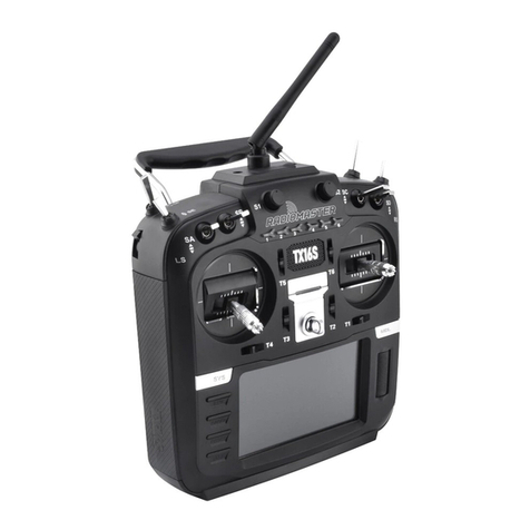
The Radio hand held command, here referred also as the Transmitter, is available in 4 different configurations:
There is only one Receiver which interfaces with these 4 different kind of devices.
In case of single engine installation, both left and right joysticks gear are active to engage the gear.
Technical specification of the Receiver is described in chapter 12.

14/39 4500 WRC - Wireless Remote Control
5.1. Description of the transmitter commands
5.2. Description of the transmitter LED lights

4500 WRC - Wireless Remote Control 15/39
6. The Receiving Station
We recommend following the instructions below, in order
to set up a properly operating radio remote control
system. The radio remote control should be installed by
qualified personnel only.
In case the vessel is built in wood, the receiving unit can
be installed either under/in the dashboard or on the fly
bridge.
In case the vessel is built in metal (e.g. ferry boat) follow
the instruction here below.
Install the receiving with no electromagnetic shielding.
Do not install the unit on metal surfaces, if possible.
Do not bypass the machine’s safety systems; follow the
manufacturer’s instructions.
Do not install the receiving unit too high above the
ground (more than 1020 meters). At these heights the
unit may receive local radio signals that could disturb
transmitting operations.
To prevent water infiltrations, install the receiving
unit vertically, with the cable clamps and any other
connections at the bottom, as shown in the figure.
In case of strong mechanical vibrations, place a rubber
shock-absorber between the machine and the receiver
(dampers).
S
T
O
P
T
E
S
E
R
S
E
R
T
E
R
E
S
E
T
P
O
T
S
RF
ANTENNA ANTENNA
RF
S
T
O
P
T
E
S
E
R
E
T
R
E
S
R
E
S
E
T
P
O
T
S
RECOMMENDED

16/39 4500 WRC - Wireless Remote Control
6.1. Receiving unit dimensions and drilling diagram
6.2. Connecting the receiver
Do not perform any operation until the equipment is powered off.
The power supply for the radio remote control should be located downstream according to installation
schemes of chapter 8.
The connection of the Receiver Unit must be done according to one of the electrical scheme
reported in the following chapters . It is mandatory to switch the Receiver Unit at the same time
with the Actuators.
Conductors and cables shall be selected so as to be suitable for the existing operating conditions (for
example, voltage, current, protection against electric shock, grouping of cables), as well as external
influences (for example, ambient temperature, presence of water or corrosive substances, mechanical
stresses-including stresses during installation- and fire hazards). When cables are installed on hoisting
machines used in the open air (outside buildings or other protective structures), they shall be suitable
for outdoor use (for example, UV-resistant, adequate temperature range), or be appropriately protected.
The wire connections between the receiving unit and the machine should respect the Standard
EN60204 and must be stranded. The wires must have a cross-section of at least 0.75 mm2 and less
than 13 mm2 and be self-extinguishing. If the equipment is used with ambient temperature of 70°C the
maximum conductor operating temperature must be greater than 75°C.
Use ferrules for conductor ends, if possible, and make sure that the terminals are fastened tightly.

4500 WRC - Wireless Remote Control 17/39
After installing, test the radio remote control make sure it works as expected. In addition, it is
very important to make sure that the STOP circuit works properly. Pressing the STOP button
during normal operation should immediately disengage the gearboxes and at the same time it
should disable all the other the functions of the Wireless Remote Control including thrusters and
anchor.
6.3. Signals outgoing the Receiver
Once the Transmitter has acquired the control of the whole 4500 electronic system
(Command LEDs lighted), the Receiver transmits via CANBus to the Actuator/(s)
the command/(s) to engage or disengage the gears through the 12 pin Deutsch
connector, all the commands for thrusters and the anchor.
Thrusters and the anchor are outputs are generated by relays with maximum
current output of 5 Amp. Each group of function is protected by a 5 Amp fuse:
Fuse F1: general PCB power supply
Fuse F2: bow thrusters
Fuse F3: stern thrusters
Fuse F4: anchor
In case of replacement of a blown fuse, refer to the here
below scheme.
(front view)

18/39 4500 WRC - Wireless Remote Control
7. Configuration of the CANbus network
The WRC is fully integrated in the 4500 electronic system and communicates with the other devices via
CANBus. How to make the installation depends from the quantity, type of engines and gearboxes and number
of command stations. In the following installation schemes, which cover the most common application cases,
you find how to connect each device to the CANBus network. In the schemes is reported only the Receiver of
the WRC because it is the only one part connected to the CANBus netwok. The WRC Receiver is always
configured with address 2 (second station).
7.1. Installation with 2 mechanical actuators – solution A
This installation scheme is valid for systems with:
WRC with up to 2 command stations and 2 engines with mechanical throttle, mechanical gearbox,
with/without trim;
WRC with up to 2 command stations and 2 hybrid engines with mechanical throttle, mechanical
gearbox, analogue outputs for electric engine inverter driven, with/without trim.

4500 WRC - Wireless Remote Control 19/39
7.2. Installation with 2 mechanical actuators – solution B
This installation scheme is valid for systems with:
WRC with up to 2 command stations and 2 engines with mechanical throttle, mechanical gearbox,
with/without trim;
WRC with up to 2 command stations and 2 hybrid engines with mechanical throttle, mechanical
gearbox, analogue outputs for electric engine inverter driven, with/without trim.
In case the installation is without the 3° station (it is the station highlighted in grey), you must
activate the end of line termination and therefore set on the actuator JP19 = ON.

20/39 4500 WRC - Wireless Remote Control
7.3. Installation with 2 mechanical actuators – solution C
Actuators are placed at the ends of the CANBus network
This installation scheme, typical for catamaran applications, is valid for systems with:
WRC with up to 2 command stations and 2 engines with mechanical throttle, mechanical gearbox,
with/without trim;
WRC with up to 2 command stations and 2 hybrid engines with mechanical throttle, mechanical
gearbox, analogue outputs for electric engine inverter driven, with/without trim.
Table of contents
