ME806-16 Series
Form #435 Rev D 5/8/19
!CAUTION!
The ME806 valve series is rated for a maximum pressure of 400 psi
and an operating temperature range of -40°F to 212°F (-40°C to
100°C). DO NOT exceed these parameters during valve operation or
use.
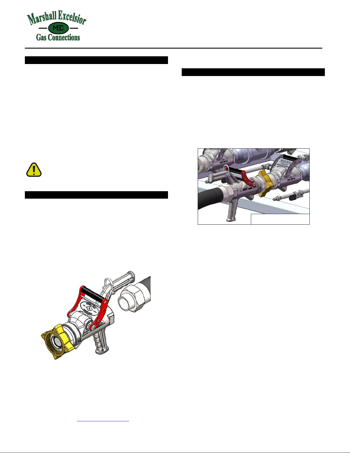
4. End Transfer –Turn off pump, then close the ME806 Transfer
valve by pushing the handle away from the ACME adapter until
the handle safety latch locks in the closed position. Close the
inlet Shut-Off valve or other connection next. Disconnect
Transfer valve.
!WARNING!
NEVER disconnect the ME806 Transfer with the valve open. Ensure
the safety latch is in the locked position (both sides of the latch
engaged in notches on body) before disconnecting valve.
*Note: this valve system is designed for minimum product loss at
disconnect. To achieve the intended low emission feature of this
transfer system, you may need to adjust your standard operating
procedure for the filling process. When using the ME868 TURBO-FLO
ACME Adapter in conjunction with ME806 Transfer valve, do not vent
the product trapped between the container service valve and the
adapter.
!WARNING!
To avoid risk of serious injury or death, never attempt to open the
ME806 Transfer Valve when it is under pressure and not properly
connected to the system with an appropriate transfer hose.
Never attempt to remove, replace or service the ball bearings in
the bearing race.
Ensure hydrostatic relief valve is aimed away from people at all
times.
Remove valve from service immediately if any ball bearings come
out of bearing race.
Remove valve from service immediately if the safety latch does not
function properly.
Remove valve from service immediately if valve seals or joints leak.
ACME Nut Service and Replacement Instructions
!WARNING!
Failure to follow the adapter service and replacement instructions
could cause risk of serious injury or death. Adapter Nut replacement
must be performed by qualified service personnel.
1. Release all system pressure before attempting to service the nut.
2. Remove the (2) Set Screws [2] from Body [1] that retain the
Adapter Nut [3] and discard.
3. Remove the Adapter Nut [3] from the Body [1] casting using the
appropriate wrench on the wrench flats provided.
4. Remove Seal [4] from the Body [1] and discard.
5. Clean all threads and sealing surfaces and install new Seal [4] into
Body [1] casting.
6. Apply Loctite #242 (blue) or equivalent thread locker to new
Adapter Nut [3] and torque to 160 to 180 Ft-lbs (217-244 Nm).
*Note: If using an ACME Cap to install, leave Cap in place until after
set screws are installed in step 7.
7. Install new Set Screws [2] and torque to 80 in-lbs (9 Nm)
*Note: Use only the (2) Set Screws [2] provided with service kit.
8. Connect a pressure source of a least 150 psi (1034 kPa) and check
for leaks (as evidenced by bubbles) at all joints and sealing
surfaces by applying a suitable leak detector solution to all joints.
Component List
1. Valve Body
2. Set Screw, Qty: 2
3. Adapter Nut
ME806 Brass
ME806S Steel
4. Adapter O-Ring
Preventative Maintenance and Safety Checks
The ME806 Transfer Valve is designed to provide a long and trouble
free service life when properly installed and maintained. Like all
mechanical devices, however, it is subject to wear and requires
preventative maintenance to maintain safe and efficient operation.
The valve contains a date of manufacture code, see above.
Perform the inspections and service as follows:
Before each use:
1. Inspect the safety latch to ensure that it is in the locked position
(both sides of the latch engaged in notches on body) prior to and
after each use. If it is not fully latched, move the handle grip
away from the ACME nut until latch is fully engaged.
2. Inspect ACME nut for worn threads. Replace nut assembly if
required. See “Periodic Checks” for important safety
instructions regarding the ACME adapter.
Periodic Checks
The following checks should be performed weekly on valves exposed to
severe service conditions such as frequent use (over 100 connections
per week) or when exposed to contaminants, corrosive agents or
extreme weather conditions. The checks should be performed at least
monthly on all other valves.
1. Adapter Nut Assembly –Inspect the hardened steel bearing races
for wear by checking the gap between the ACME nut race and the
nut adapter race. A gap greater than 0.135” (3.4mm, 2 stacked US
quarters) indicates excessive wear and MUST be removed from
service immediately, see Service and Replacement
2. Handle assembly –Inspect the valve handle, latch and springs for
proper operation. If service is required. Have handle assembly
replaced by qualified service personnel using the service
instructions provided with the replacement parts. Remove valve
from service immediately if the safety latch does not function
properly.
3. Seals –Inspect the valve seals for leaks (as evidenced by bubbles)
at all joints and sealing surfaces by apply Marshall Excelsior ”Leak
Detector” solution to all joints. If service is required, have leak
repaired by qualified service personnel using the service
instructions provided with the replacement parts. Remove valve
from service immediately if valve seals or joints leak.