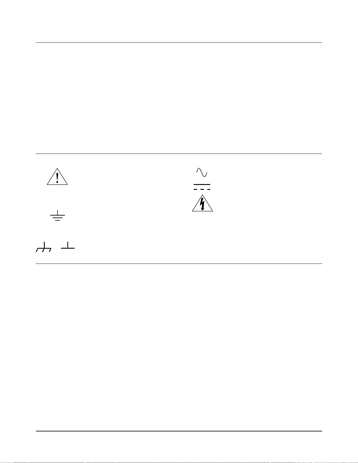
HP E2270A Owner's manual

Contents
HP E2270A, E2271A, E2272A User’s and SCPI Programming Manual
Edition 1
Contents 1
Warranty .......................................................................................................................5
Safety Symbols .............................................................................................................6
WARNINGS.................................................................................................................6
WARNINGS.................................................................................................................7
Declaration of Conformity............................................................................................8
Reader Comment Sheet ................................................................................................9
Chapter 1
Getting Started .............................................................................................................11
What’s in this Manual?...............................................................................................11
Module Descriptions...................................................................................................12
General Product Features ....................................................................................12
HP E2270A 16-Channel Form A Switch ............................................................12
HP E2271A 4x4 Matrix Switch ..........................................................................12
HP E2272A Dual 8-to-1 Relay Multiplexer ........................................................12
Wiring and Configuration...........................................................................................13
Identfying M-Modules ........................................................................................13
Assembling the Field Wiring Connector ............................................................14
HP E2270A Form A Switch Wiring Information ...............................................15
HP E2271A 4x4 Matrix Switch Wiring Information ..........................................16
HP E2272A Dual 8-to-1 Relay Multiplexer Wiring Information .......................17
Setting HP E2272A Multiplexer Size .................................................................18
Chapter 2
SCPI Programming .....................................................................................................19
Using This Chapter.....................................................................................................19
Example1: Initial Operation........................................................................................19
Closing and Opening Channels...................................................................................21
Channel Lists .......................................................................................................21
Example 2: Closing Multiple Channels......................................................................22
Chapter 3
SCPI Command Reference .........................................................................................25
DIAGnostic Subsystem...............................................................................................28
DIAGnostic:INTerrupt:LINE <intr_line> ...........................................................28
DIAGnostic:INTerrupt:LINE? ............................................................................29
DIAGnostic:TEST? .............................................................................................29
DISPlay Subsystem.....................................................................................................31
DISPlay:MONitor:[STATe] <boolean> ..............................................................31
DISPlay:MONitor:[STATe]? ..............................................................................32
[ROUTe] Subsystem...................................................................................................33
[ROUTe]:CLOSe <channel list> .........................................................................33
[ROUTe]:CLOSe? <channel list> .......................................................................35
[ROUTe]:OPEN <channel list> ..........................................................................36
[ROUTe]:OPEN? <channel list> ........................................................................38
STATus Subsystem.....................................................................................................40
SYSTem Subsystem ...................................................................................................41

2 Contents
SYSTem:ERRor? ................................................................................................41
SYSTem:VERSion? ............................................................................................42
IEEE Common Commands.........................................................................................43
*CLS ....................................................................................................................43
*ESE <mask> ......................................................................................................43
*ESE? ..................................................................................................................44
*ESR? ..................................................................................................................46
*IDN? ..................................................................................................................47
*OPC ...................................................................................................................47
*OPC? .................................................................................................................47
*RCL <state> ......................................................................................................48
*RST ....................................................................................................................48
*SAV <state> ......................................................................................................49
*SRE <mask> ......................................................................................................49
*SRE? ..................................................................................................................50
*STB? ..................................................................................................................51
*TST? ..................................................................................................................52
*WAI ...................................................................................................................52
SCPI Command Quick Reference ..............................................................................53
Common Command Quick Reference........................................................................54
Chapter 4
Register Programming ................................................................................................55
Introduction.................................................................................................................55
Block Diagram Description ........................................................................................55
Module Control ...................................................................................................55
ID EEPROM .......................................................................................................56
Row and Column Drivers ....................................................................................56
Driver Power Switch ...........................................................................................56
Relay Coils ..........................................................................................................56
Reset and Power Conditioning ............................................................................56
Register Addressing in the VXIbus Environment ......................................................58
Logical Address ...................................................................................................58
A16/A24 Memory Mapping ...............................................................................58
Determining a Module’s A16 Base Address .......................................................59
Addressing A16 Registers ...................................................................................60
Addressing A24 Registers ...................................................................................60
Program Example .......................................................................................................61
Switch M-Module A16 Register Descriptions............................................................63
VXI ID Register ..................................................................................................63
VXI Device Type Register ..................................................................................63
VXI Status/Control Register ...............................................................................64
A24 Offset Register .............................................................................................65
Interrupt Selection Register .................................................................................65
Switch M-Module A24 Register Descriptions............................................................66
Status Register .....................................................................................................67
Control Register ..................................................................................................68
Reserved Registers ..............................................................................................69

Contents 3
Row Set and Reset Registers ...............................................................................69
Matrix Drive to Channel Mappings ....................................................................71
Unused Registers .................................................................................................72
ID EEPROM Register .........................................................................................72
Appendix A
Specifications ................................................................................................................75
M-Module Specification Compliance.........................................................................75
HP E2270A 16-Channel Form A Switch Specifications............................................75
HP E2271A 4x4 Matrix Switch Specifications ..........................................................77
HP E2272A Dual 8-to-1 Relay Multiplexer Specifications........................................79
Index ................................................................................................................................81

4 Contents

5
Certification
Hewlett-Packard Company certifies that this product met its published specifications at the time of shipment from the factory. Hewlett-
Packard further certifies that its calibration measurements are traceable to the United States National Institute of Standards and
Technology (formerly National Bureau of Standards), to the extent allowed by that organization’s calibration facility, and to the
calibration facilities of other International Standards Organization members.
Warranty
This Hewlett-Packard product is warranted against defects in materials and workmanship for a period of three years from date of shipment.
Duration and conditions of warranty for this product may be superseded when the product is integrated into (becomes a part of) other HP
products. During the warranty period, Hewlett-Packard Company will, at its option, either repair or replace products which prove to be
defective.
For warranty service or repair, this productmust be returned toa service facility designated by Hewlett-Packard (HP).Buyer shall prepay
shipping charges to HP and HP shall pay shipping charges to return the product to Buyer. However, Buyer shall pay all shipping charges,
duties, and taxes for products returned to HP from another country
HP warrants that its software and firmware designated by HP for use with a product will execute its programming instructions when
properly installed on that product. HP does not warrant that the operation of the product, or software, or firmware will be uninterrupted
or error free.
Limitation Of Warranty
The foregoing warranty shall not apply todefects resulting from improper or inadequate maintenance byBuyer, Buyer-supplied products
or interfacing, unauthorized modification or misuse, operation outside of the environmental specifications for the product, or improper
site preparation or maintenance.
The design and implementation of any circuit on this product is the sole responsibility of the Buyer. HP does not warrant the Buyer’s
circuitry or malfunctions of HP products that result from the Buyer’s circuitry. In addition, HP does not warrant any damage that occurs
as a result of the Buyer’s circuit or any defects that result from Buyer-supplied products.
NO OTHER WARRANTY IS EXPRESSED OR IMPLIED. HP SPECIFICALLY DISCLAIMS THE IMPLIED WARRANTIES OF
MERCHANTABILITY AND FITNESS FOR A PARTICULAR PURPOSE.
Exclusive Remedies
THE REMEDIES PROVIDED HEREIN ARE BUYER’S SOLE AND EXCLUSIVE REMEDIES. HP SHALL NOT BE LIABLE FOR
ANY DIRECT, INDIRECT, SPECIAL, INCIDENTAL, OR CONSEQUENTIAL DAMAGES, WHETHER BASED ON CONTRACT,
TORT, OR ANY OTHER LEGAL THEORY.
Notice
The information contained in this document is subject to change without notice. HEWLETT-PACKARD (HP) MAKES NO
WARRANTY OF ANY KIND WITH REGARD TO THIS MATERIAL, INCLUDING, BUT NOT LIMITED TO, THE IMPLIED
WARRANTIES OF MERCHANTABILITY AND FITNESS FOR A PARTICULAR PURPOSE. HP shall not be liable for errors
contained herein or for incidental or consequential damages in connection with the furnishing, performance or use of this material. This
document contains proprietary information which is protected by copyright. All rights are reserved. No part of this document may be
photocopied, reproduced, or translated to another language without the prior written consent of Hewlett-Packard Company. HP assumes
no responsibility for the use or reliability of its software on equipment that is not furnished by HP.
U.S. Government Restricted Rights
The Software and Documentation have been developed entirely at private expense. They are delivered and licensed as "commercial
computer software" as defined in DFARS 252.227- 7013 (Oct 1988), DFARS 252.211-7015 (May 1991) or DFARS 252.227-7014 (Jun
1995), as a "commercial item" as defined in FAR 2.101(a), or as "Restricted computer software" as defined in FAR 52.227-19 (Jun
1987)(or any equivalent agency regulation or contract clause), whichever is applicable. You have only those rights provided for such
Software and Documentation by the applicable FAR or DFARS clause or the HP standard software agreement for the product involved
HP E2270A, E2271A, E2272A User’s and SCPI Programming Manual
Edition 1
Copyright © 1997 Hewlett-Packard Company. All Rights Reserved.

6
Safety Symbols
Instruction manual symbol affixed to
product. Indicates that the user must refer to
the manual for specific WARNING or
CAUTION information to avoid personal
injury or damage to the product.
Alternating current (AC)
Instruction manual symbol affixed to
product. Indicates that the user must refer to
the manual for specific WARNING or
CAUTION information to avoid personal
injury or damage to the product.
Indicates the field wiring terminal that must
be connected to earth ground before
operating the equipment—protects against
electrical shock in case of fault.
Direct current (DC).
Indicates hazardous voltages.
or Frameorchassisground terminal—typically
connects to the equipment's metal frame.
WARNING Calls attention to a procedure, practice, or
condition that could cause bodily injury or
death.
CAUTION Calls attention to a procedure, practice, or
conditionthatcouldpossiblycausedamageto
equipment or permanent loss of data.
WARNINGS
The following general safety precautions must be observed during all phases of operation, service, and repair of this product. Failure to
comply with these precautions or with specific warnings elsewhere in this manual violates safety standards of design, manufacture, and
intended use of theproduct. Hewlett-Packard Company assumes no liability for the customer's failure to comply with these requirements.
Ground the equipment: For Safety Class 1 equipment (equipment having a protective earth terminal), an uninterruptible safety earth
ground must be provided from the mains power source to the product input wiring terminals or supplied power cable.
DO NOT operate the product in an explosive atmosphere or in the presence of flammable gases or fumes.
For continued protection against fire, replace the line fuse(s) only with fuse(s) of the same voltage and current rating and type. DO NOT
use repaired fuses or short-circuited fuse holders.
Keep away from live circuits: Operating personnel must not remove equipment covers or shields. Procedures involving the removal of
covers or shields are for use by service-trained personnel only. Under certain conditions, dangerous voltages may exist even with the
equipment switched off. To avoid dangerous electrical shock, DO NOT perform procedures involving cover or shield removal unless you
are qualified to do so.
DO NOT operate damaged equipment: Whenever it is possible that the safety protection features built into this product have been
impaired, either through physical damage, excessive moisture, or any other reason, REMOVE POWER and do not use the product until
safe operation can be verified by service-trained personnel. If necessary, return the product to a Hewlett-Packard Sales and Service Office
for service and repair to ensure that safety features are maintained.
DO NOT service or adjust alone: Do not attempt internal service or adjustment unless another person, capable of rendering first aid and
resuscitation, is present.
DO NOT substitute parts or modify equipment: Because of the danger of introducing additional hazards, do not install substitute parts
or perform any unauthorized modification to the product. Return the product to a Hewlett-Packard Sales and Service Office for service
and repair to ensure that safety features are maintained.
Documentation History
All Editions and Updates of this manual and their creation date are listed below. The first Edition of the manual is Edition 1. The Edition
number increments by 1 whenever the manual is revised. Updates, which are issued between Editions, contain replacement pages to
correct or add additional information to the current Edition of the manual. Whenever a new Edition is created, it will contain all of the
Update information for the previous Edition. Each new Edition or Update also includes a revisedcopy of this documentation history page.
Edition 1 . . . . . . . . . . . . . . . . . . . . . . . . . . . . . . . . . . . . . . . . . . . . . . . .June 1997

7
WARNINGS
In a cleanroom environment (see Specifications, Appendix A) the HP E2270A, E2271A, and E2272A are capable of switching voltages
that could cause bodily injury or death to an operator. Special precautions must be adhered to (discussed below) when applying voltages
in excess of 60 Vdc, 30 Vac rms or 42.4 Vac peak for a continuous, complex waveform.
Module connectors, and test signal cables connected to them, must be made NON-accessible to an operator who has not been told
to access them: It is a supervisor’s responsibility to advise an operator that dangerous voltages exist when the operator is instructed to
access connectors and cables carrying these voltages. Making cables and connectors that carry hazardous voltages inaccessible is a
protective measure keeping an operator from inadvertant or unknowing contact with these harmful voltages. Cables and connectors are
considered inaccessible if a tool (e.g., screwdriver, wrench, socket, etc.) or a key (equipment in a locked cabinet) is required to gain access
to them. Additionally, the operator cannot have access to a conductive surface connected to any cable conductor (High, Low or Guard).
Assure the equipment under test has adequate insulation between the cable connections and any operator-accessible parts (doors,
covers, panels, shields, cases, cabinets, etc.): Verify there are multiple and sufficient protective means (rated for the voltages you are
applying) to assure the operator will NOT come into contact with any energized conductor even if one of the protective means fails to
work as intended. For example, the inner side of a case, cabinet, door, cover or panel can be covered with an insulating material as well
as routing the test cables to the module’s front panel connectors through non-conductive, flexible conduit such as that used in electrical
power distribution.

8
Jim White, QA Manager
European contact: Your local Hewlett-Packard Sales and Service Office or Hewlett-Packard GmbH, Depart-
ment HQ-TRE, Herrenberger Straße 130, D-71034 Böblingen, Germany (FAX +49-7031-14-3143)
Declaration of Conformity
according to ISO/IEC Guide 22 and EN 45014
Manufacturer’s Name: Hewlett-Packard Company
Loveland Manufacturing Center
Manufacturer’s Address: 815 14th Street S.W.
Loveland, Colorado 80537
declares, that the product:
Product Name: 16-Channel Form A Switch, 4x4 Matrix Switch, Dual 8-to-1 Multiplexer M-Modules
Model Number: HP E2270A, E2271A, E2272A
Product Options: All
conforms to the following Product Specifications:
Safety: IEC 1010-1 (1990) Incl. Amend 2 (1996)/EN61010-1 (1993)
CSA C22.2 #1010.1 (1992)
UL 3111-1 (1994)
EMC: CISPR 11:1990/EN55011 (1991): Group1, Class A
EN61000-3-2:1995 Class A
EN50082-1:1992
IEC 801-2:1991: 4kVCD, 8kVAD
IEC 801-3:1984: 3 V/m
IEC 801-4:1988: 1kV Power Line, 0.5kV Signal Lines
ENV50141:1993/prEN50082-1 (1995): 3 Vrms
ENV50142:1994/prEN50082-1 (1995): 1 kV CM, 0.5 kV DM
IEC1000-4-8:1993/prEN50082-1 (1995): 3 A/m
EN61000-4-11:1994/prEN50082-1 (1995): 30%, 10ms 60%, 100ms
Supplementary Information: The product herewith complies with the requirements of the Low Voltage Directive
73/23/EEC and the EMC Directive 89/336/EEC (inclusive 93/68/EEC) and carries the "CE" mark accordingly.
Tested in a typical configuration in an HP C-Size VXI mainframe.
April 7, 1997

NO POSTAGE
NECESSARY
IF MAILED
IN THE
UNITED STATES
fold here
Pl
ease
f
o
ld
an
d
tape
f
or ma
ili
ng
Reader Comment Sheet
HP E2270A, E2271A, E2272A Switch M-Modules User’s Manual
Edition 1
You can help us improve our manuals by sharing your comments and suggestions. In appreciation of your time, we will
enter you in a quarterly drawing for a Hewlett-Packard Palmtop Personal Computer (U.S. government employees
are not eligible for the drawing).
Your Name
Company Name
Job Title
Address
City, State/Province
Country
Zip/Postal Code
Telephone Number with Area Code
Please list the system controller, operating system, programming language, and plug-in modules you are using.
BUSINESS REPLY MAIL
FIRST CLASS PERMIT NO. 37 LOVELAND, CO
POSTAGE WILL BE PAID BY ADDRESSEE
HEWLETT-PACKARD COMPANY
Measurement Systems Division
Learning Products Department
P.O. Box 301
Loveland, CO 80539-9984
fold here
Please pencil-in one circle for each statement below: Disagree Agree
•The documentation is well organized. OOOOO
•
Instructions are easy to understand. OOOOO
•
The documentation is clearly written. OOOOO
•Examples are clear and useful. OOOOO
•
Illustrations are clear and helpful. OOOOO
•
The documentation meets my overall expectations. OOOOO
Please write any comments or suggestions below–be specific.
cut along this line


Getting Started 11
Chapter 1
Getting Started
What’s in this Manual?
This manual contains module descriptions, configuration and wiring
information, SCPI programming information, register programming
information, and specifications for these M-Modules:
•HP E2270A 16-Channel Form A Switch
•HP E2271A 4x4 Matrix Switch
•HP E2272A Dual 8-to-1 Relay Multiplexer
In this manual, where the information is identical for all three M-Modules,
they will be referred to collectively as the Switch M-Modules. Differences
between the modules include switching schematics, wiring diagrams,
channel numbering, and specifications. These differences are documented
individually for each module.
The Switch M-Modules are intended to be installed on an M-Module
Carrier. When it is necessary to reference a particular carrier, the HP E2251
C-Size VXIbus M-Module Carrier will be used.
Caution The Switch M-Modules use latching relays that retain their last
programmed state whenever power is removed.
If you are programming at the register level, THESE RELAYS
DO NOT RESET THEMSELVES AUTOMATICALLY WHEN
POWER IS RE-APPLIED. This means that closed relays will
remain closed when power is re-applied, and will stay closed
until you open them programmatically.
If you are using the D-SCPI driver, the driver WILL open all
Switch M-Module relays shortly after power is re-applied to the
Command Module.
Caution The Switch M-Modules DO NOT have provision for on-board
current limiting components. If it is possible that input current
could exceed 2 A DC or 2 A AC-Peak per channel, you must
install external current limiting circuitry.

12 Getting Started
Module Descriptions
General Product
Features •FIFO register structure allows fast system operation.
•Standard 44-Pin D-Sub connectors provide a common interface to all
three Switch M-Modules.
•Single-width M-Modules provide high-density and maximum
flexibility of configuration.
•Low-cost switching in VXI environment when used in an HP E2251
M-Module Carrier.
HP E2270A
16-Channel Form A
Switch
The HP E2270A is ageneral purpose relay switch consisting of 16 one-wire
switches on a single-width M-Module. This module can be used to connect
test points on a device under test to instrumentation or to switch factory
automation and fixturing. The switching schematic and user connector
diagram are shown in Figure 1-2 on page 15.
HP E2271A 4x4
Matrix Switch The HP E2271A is a 4x4 matrix consisting of 16DPST relaysconfigured as
4 rows and 4 columns of two-wire switches. This module can connect
multiple instruments to multiple points in your test system. This provides
flexible interconnections between test points, instrumentation, factory
automation, and test fixtures. The switching schematic and user connector
diagram are shown in Figure 1-3 on page 16.
HP E2272A Dual
8-to-1 Relay
Multiplexer
The HP E2272A provides two separate 8-to-1, two-wire multiplexers.
Alternatively, you can move a jumper to connect the common channels of
each multiplexer together and createa single 16-to-1, two-wire multiplexer.
The switching schematic and user connector diagram are shown in Figure
1-4 on page 17.

Getting Started 13
Wiring and Configuration
Thissectiondescribeshow to connectuserwiringtoeach ofthethreeSwitch
M-Modules. It also describes how to configure the HP E2272A as a dual
8-to-1 or a single 16-to-1 multiplexer.
Note The procedures in this section assume the M-Module(s) have already been
installed into an M-Module Carrier. Since installation is dependent on the
carrier used, instructions for installing M-Modules into the carrier are not
included here. Refer to your M-Module carrier documentation for
installation instructions. Each Hewlett-Packard M-Module is shipped with
identifying labels that you should install on the carrier.
Identfying
M-Modules The Switch M-Modules havea module ID number printed onthe PC-board.
The ID numberconsists of a modelnumber prefix/PC-board number suffix.
For example, “E2270-66501” is the ID number for the HP E2270
M-Module. ID number locations are shown in Figures 1-2, 1-3, and 1-4.
WARNING SHOCK HAZARD. Only service-trained personnel who are
aware of the hazards involved should install, remove, or
configure the modules. Before installing or removing any
module or carrier, disconnect power from the mainframe and
user wiring.
Caution MAXIMUM VOLTAGE/CURRENT. The maximum voltage that
may be applied to any connector on the HP E2270A, E2271A, or
E2272A is 200 VDC, 125 VAC rms, or 175 VAC peak. These
limits apply only if the product is installed in a
humidity-controlled (<60% RH) environment where airborne
contaminants and transients are controlled, and NO relay
connection is made to power mains. If these conditions
CANNOT be maintained, then the maximum voltage is 60 VDC,
48 VAC-rms or 68 VAC-peak.
The maximum current (non-inductive) that may be appied to the
HP E2270A, E2271A, or E2272A is:
Per Switch: 2 ADC, 2 AAC peak
Per Module: 8 ADC, 8 AAC peak
Caution STATIC ELECTRICITY. Static electricity is a major cause of
component failure. To prevent damage to the electrical
components on an M-Module or the carrier, observe anti-static
techniques whenever installing, removing, or working on a
carrier or M-Module.

14 Getting Started
Assembling the
Field Wiring
Connector
Each Switch M-Module includes a 44-pin connector and hood (HP kit part
number E2273-01203). You must supply your own cable. The drawing
below shows how to connect wiring and assemble the connector and hood.
Figure 1-1. Assembling the Field Wiring Connector
5. Solder wires to connector.
4. Use 24 gauge or smaller stranded wire.
6. Assemble connector using supplied machine
2. Release the latch
on the side of the hood.
1. If necessary, disassemble
the connector hood. Discard
the three self-tapping screws
supplied with the hood.
3. Assemble bezel and
cable clamp before wiring
cable to connector.
Strip wires 1/8”
screws. DO NOT overtighten screws.

Getting Started 15
HP E2270A Form A Switch Wiring Information
Figure 1-2. HP E2270A User Connector and Switching Schematic
MAXIMUMVOLTAGE/CURRENT. The maximumvoltage
that may be applied to any connector on the HP
E2270A, E2271A, or E2272A is 200 VDC, 125 VAC rms,
or 175 VAC peak--these limits apply only if the product
is installed in a humidity-controlled (<60% RH)
environment where airborne contaminants and
transients are controlled, and there is NOT a relay
connection made to power mains. If these conditions
CANNOT be maintained, then the maximum voltage is
60 VDC, 48 VAC-rms or 68 VAC-peak.
The maximum current (non-inductive) that may be
applied to the HP E2270A, E2271A, or E2272A is:
Per Switch: 2 ADC, 2 AAC peak
Per Module: 8 ADC, 8 AAC peak
Channel 0
Channel 1
Channel 2
Channel 3
1 CH0_NO
16 CH0_COM
2 CH1_NO
17 CH1_COM
3 CH2_NO
18 CH2_COM
4 CH3_NO
19 CH3_COM
Channel 4
Channel 5
Channel 6
Channel 7
5 CH4_NO
20 CH4_COM
6 CH5_NO
21 CH5_COM
7 CH6_NO
22 CH6_COM
8 CH7_NO
23 CH7_COM
31 - 42
Channel 8
Channel 9
Channel 10
Channel 11
9 CH8_NO
24 CH8_COM
10 CH9_NO
25 CH9_COM
11 CH10_NO
26 CH10_COM
12 CH11_NO
27 CH11_COM
Channel 12
Channel 13
Channel 14
Channel 15
13 CH12_NO
28 CH12_COM
14 CH13_NO
29 CH13_COM
15 CH14_NO
30 CH14_COM
43 CH15_NO
44 CH15_COM
User
Connector
Pins
User
Connector
Pins

16 Getting Started
HP E2271A 4x4 Matrix Switch Wiring Information
Figure 1-3. HP E2271A User Connector and Switching Schematic
MAXIMUMVOLTAGE/CURRENT.Themaximumvoltage
that may be applied to any connector on the HP
E2270A, E2271A, or E2272A is 200 VDC, 125 VAC rms,
or 175 VAC peak--these limits apply only if the product
is installed in a humidity-controlled (<60% RH)
environment where airborne contaminants and
transients are controlled, and there is NOT a relay
connection made to power mains. If these conditions
CANNOT be maintained, then the maximum voltage is
60 VDC, 48 VAC-rms or 68 VAC-peak.
The maximum current (non-inductive) that may be
applied to the HP E2270A, E2271A, or E2272A is:
Per Switch: 2 ADC, 2 AAC peak
Per Module: 8 ADC, 8 AAC peak
4 ROW_0_HI
20 ROW_0_LO
6 ROW_1_HI
22 ROW_1_LO
8 ROW_2_HI
24 ROW_2_LO
10 ROW_3_HI
26 ROW_3_LO
18 COL_0_HI
User Connector Pins
User Connector Pins
1, 3, 5, 7, 9, 11, 13, 14, 17,
19, 21, 23, 25, 27, 29, 32-44
Channel 00 Channel 01 Channel 02 Channel 03
Channel 10 Channel 11 Channel 12 Channel 13
2 COL_0_LO
31 COL_1_HI
16 COL_1_LO
28 COL_2_HI
12 COL_2_LO
30 COL_3_HI
15 COL_3_LO
Channel 20 Channel 21 Channel 22 Channel 23
Channel 30 Channel 31 Channel 32 Channel 33

Getting Started 17
HP E2272A Dual 8-to-1 Relay Multiplexer Wiring Information
Figure 1-4. HP E2272A User Connector and Switching Schematic
MAXIMUM
VOLTAGE/CURRENT
.
Th
emax
i
mumvo
lt
age
that may be applied to any connector on the HP
E2270A, E2271A, or E2272A is 200 VDC, 125 VAC rms,
or 175 VAC peak--these limits apply only if the product
is installed in a humidity-controlled (<60% RH)
environment where airborne contaminants and
transients are controlled, and there is NOT a relay
connection made to power mains. If these conditions
CANNOT be maintained, then the maximum voltage is
60 VDC, 48 VAC-rms or 68 VAC-peak.
The maximum current (non-inductive) that may be
applied to the HP E2270A, E2271A, or E2272A is:
Per Switch: 2 ADC, 2 AAC peak
Per Module: 8 ADC, 8 AAC peak
1 CH0_HI
2 CH0_LO
18 CH1_HI
33 CH1_LO
17 CH2_HI
32 CH2_LO
16 CH3_HI
31 CH3_LO
22 CH4_HI
6 CH4_LO
21 CH5_HI
5 CH5_LO
20 CH6_HI
4 CH6_LO
19 CH7_HI
3 CH7_LO
34 - 41
25 CH8_HI
9 CH8_LO
26 CH9_HI
10 CH9_LO
27 CH10_HI
11 CH10_LO
28 CH11_HI
12 CH11_LO
13 CH12_HI
29 CH12_LO
15 CH13_HI
14 CH13_LO
30 CH14_HI
44 CH14_LO
43 CH15_HI
42 CH15_LO
8 MUXB_HI_COM
24 MUXB_LO_COM
Channel 8
Channel 9
Channel 10
Channel 11
Channel 12
Channel 13
Channel 14
Channel 15
Channel 0
Channel 1
Channel 2
Channel 3
Channel 4
Channel 5
Channel 6
Channel 7
23 MUXA_HI_COM
7 MUXA_LO_COM
User Connector Pins
Single/Dual Mux. Jumpers
User Connector Pins

18 Getting Started
Setting HP E2272A
Multiplexer Size Figure 1-4 shows the two jumper positions for the HP E2272A. When in
position A (jumper not connecting one row of pins), the module is
configured as a dual 8-to-1 multiplexer. When in position B (jumper
connecting all pins), the module is configured as a single 16-to-1
multiplexer. The HP E2272A leaves the factory with the jumper placed in
position A (dual 8-to-1 multiplexer). If you need to change this jumper
postion, it must be done before installing the M-Module onto the carrier.
Figure 1-5. HP E2272A Jumper Positions
B
Single 16-to-1 Multiplexer Position
ADual 8-to-1 Multiplexer Position

SCPI Programming 19Chapter 2
Chapter 2
SCPI Programming
Using This Chapter
This chapter contains SCPI program examples thatdemonstrate how to read
a module ID, perform self-test, and open and close channels. The program
examples are written in C language and can be used on any of the three
Switch M-Modules. To run one of these programs you must have the HP
SICL Library, the HP VISA Library, an HP-IB interface module installed in
an external PC, an HP E1406 Command Module, and a Switch M-Module
installed on the HP E2251 Carrier.
Example1: Initial Operation
The following example reads the module ID string, performs module
self-test, and displays the results. This program can be used on any of the
three Switch M-Modules.
#include <visa.h>
#include <stdio.h>
#include <stdlib.h>
/* Interface address is 9, M-Module secondary address is 3*/
#define INSTR_ADDR “GPIB0::9::3::INSTR”
int main()
{ViStatus errStatus; /*Status from each VISA call*/
ViSession viRM; /*Resource mgr. session */
ViSession m_mod; /* M-module session */
char id_string[256]; /*ID string*/
char selftst_string[256]; /*self-test string*/
/* Open the default resource manager */
errStatus = viOpenDefaultRM ( &viRM);
if(VI_SUCCESS > errStatus){
printf(“ERROR: viOpenDefaultRM() returned 0x%x\n”,errStatus);
return errStatus;}
/* Open the M-Module instrument session */
errStatus = viOpen(viRM,INSTR_ADDR, VI_NULL,VI_NULL,&m_mod);
if(VI_SUCCESS > errStatus){
printf(“ERROR: viOpen() returned 0x%x\n”,errStatus);
return errStatus;}
(program continued on next page)

20 SCPI Programming Chapter 2
/* Reset the M-Module */
errStatus = viPrintf(m_mod, “*RST\n”);
if(VI_SUCCESS > errStatus){
printf(“ERROR: viPrintf() returned 0x%x\n”,errStatus);
return errStatus;}
/* Perform M-Module Self-Test */
errStatus = viQueryf(m_mod,”*TST?\n”,”%t”,selftst_string);
if (VI_SUCCESS > errStatus) {
printf(“ERROR: viPrintf() returned 0x%x\n”,errStatus);
return errStatus;}
printf(“Self Test Result is %s\n”,selftst_string);
/* Query the M-Module ID string */
errStatus = viQueryf(m_mod,”*IDN?\n”,”%t”,id_string);
if (VI_SUCCESS > errStatus) {
printf(“ERROR: viPrintf() returned 0x%x\n”,errStatus);
return errStatus;}
printf(“ID is %s\n”,id_string);
/* Close the M_Module Instrument Session */
errStatus = viClose (m_mod);
if (VI_SUCCESS > errStatus) {
printf(“ERROR: viClose() returned 0x%x\n”,errStatus);
return 0;}
/* Close the Resource Manager Session */
errStatus = viClose (viRM);
if (VI_SUCCESS > errStatus) {
printf(“ERROR: viClose() returned 0x%x\n”,errStatus);
return 0;}
return VI_SUCCESS;
}
This manual suits for next models
2
Table of contents
Other HP Multiplexer manuals
Popular Multiplexer manuals by other brands

Deutsches Center
Deutsches Center DCL-MUX-300 user manual

Alcatel-Lucent
Alcatel-Lucent 1511 BA Brochure & specs

Giga-tronics
Giga-tronics ASCOR 7014 user manual

Syncronorm
Syncronorm SyncroADC operating manual

HORNER
HORNER HE693SNPMPX user manual

Beijing Huahuan Electronics
Beijing Huahuan Electronics H9MO-1641S user guide