flexicoil 6000 User manual

Printed in Canada Copyright © 1998 - 2003 by CNH Canada, Ltd. All rights reserved.
6000
NO-TILL AIR DRILL
OPERATOR’S MANUAL
RD-331V4
Ltd.
Starting at Serial No. DOC-114001
Canada:
CNH Canada, Ltd.
1000 - 71st Street East
P.O. Box 1928
Saskatoon, Saskatchewan
S7K 3S5
The content of this book was based on the most current information available as of the
date of copyright. It is the policy of CNH Canada, Ltd. to improve and develop our
products continuously. We reserve the right to make changes or add improvements, at any
time, without incurring any obligation to make such changes on machines previously sold.

EMPLOYER / OPERATOR CHECK LIST
In compliance with OSHA Standard 1928.57; all employers are required to instruct all operators, upon initial assignment
and at least annually thereafter, on practices for safe operation and servicing of this implement, stressing the following items:
- Keep all guards in place when the machine is in operation.
- Permit no riders on farm field equipment other than persons required for inspection or assistance in machine
operation.
- Stop engine, disconnect the power source, and wait for all machine movement to stop before servicing, adjusting,
cleaning, or unclogging the equipment, except where the machine must be running to be properly serviced or
maintained, in which case the employer shall instruct employees as to all steps and procedures which are necessary
to safely service or maintain the equipment.
- Make sure everyone is clear of machinery before starting the engine, engaging the power, or operating the machine.
- Instruct persons on safe operating, moving and transport practices.
- Instruct persons on the importance of proper jack placement before unhooking from the machine in field or transport
positions.
- Review lubrication requirements and practices. Check tire pressures.
- Instruct on the importance of safety chain and warning light safety devices, available for this implement.
- Review and be familiar with information detailed in the Safety, Operation, Maintenance and Adjustment sections
in this manual.
This sign-off chart has been included for your record keeping convenience.
Date: Signature of Operator Signature of Employer

REPAIR PARTS
i
299433C
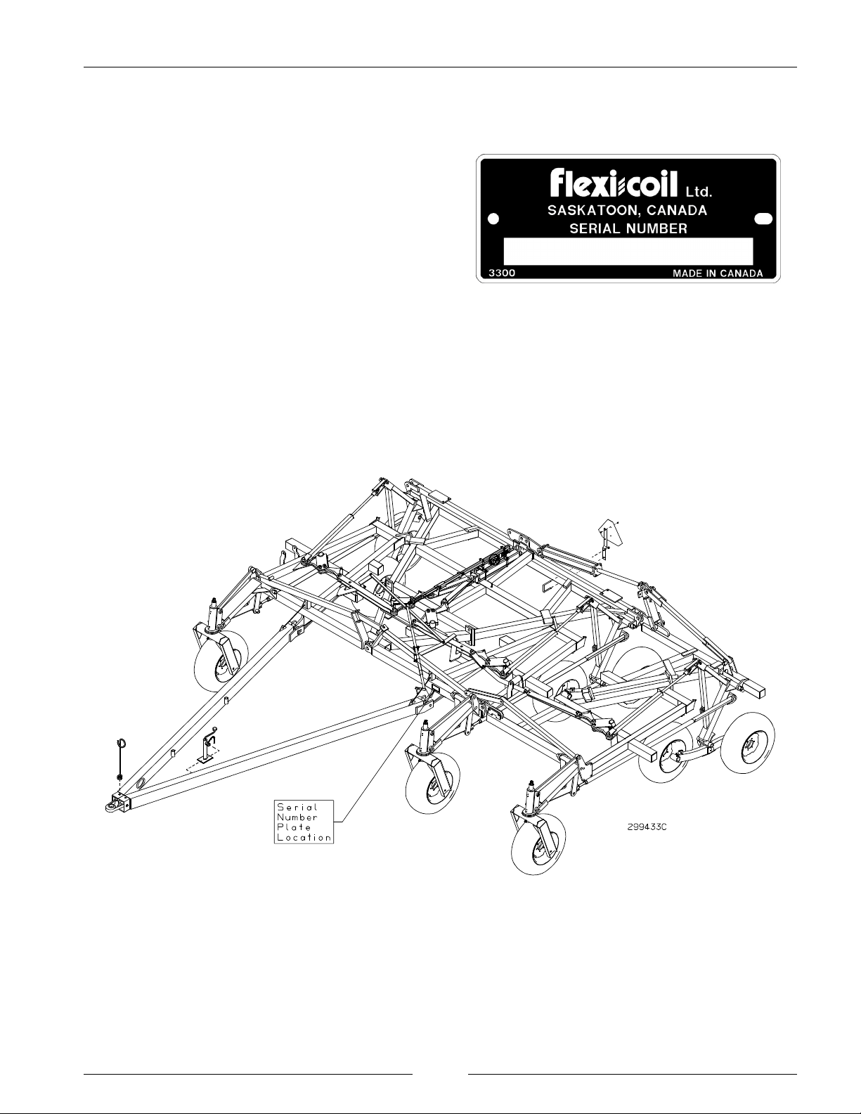
REPAIR PARTS IDENTIFICATION
The 6000 No Till Drill has a Serial Number Plate attached
at the location shown to identify the components installed
on this machine. The plate looks like the sample with a
serial number stamped on.
For easy reference, locate the Serial Number Plate at the
location shown on the figure. Record the numbers on this
sheet. When requiring repair parts, take this number into
your dealer.

REPAIR PARTS
ii
This Page is Left Blank

6000 NO-TILL AIR DRILL
iii
TABLE OF CONTENTS
Pages listed are a table of contents for that section
Section - Title ............................. Page
1- SAFETY ............................... 1-1
Safety
General Safety Practices
Safety During Operation
Safety During Transport
Safety During Servicing
Safety Decals
Safety Decal Locations
Hand Signals
2 - OPERATION ........................... 3-1
Connecting
Folding and Unfolding
Field Operation
Transporting
Disconnecting from the Tractor
3- MAINTENANCE ......................... 4-1
Servicing Safety Precautions
Daily Maintenance (Every 10 Hours)
Weekly Maintenance (Every 50 Hours)
Semi-Annual Maintenance (Every 200 Hours)
Before Seasonal Operation or Before Storage
Tire Pressures
Maintenance Table
Changing Tires
4- ADJUSTMENTS ........................ 4-1
Air Drill Leveling
Center Section Initial Leveling
Wing Initial Leveling
Setting the Frame Height
Final Leveling
Hitch Adjustment
5 - TROUBLESHOOTING ................... 5-1
Troubleshooting Table
SPECIFICATIONS
Machine Dimensions
Machine Specifications - Imperial Units
Machine Specifications - Metric Units
Tire Pressure and Wheel Bolt Torque

iv
This Page is Left Blank

page 1-1
SECTION 1
SAFETY
CONTENTS OF THIS SECTION
Page
SAFETY ............................................................ 1-3
GENERAL SAFETY PRACTICES ...................................... 1-4
SAFETY DURING OPERATION ........................................ 1-4
SAFETY DURING TRANSPORT ....................................... 1-4
SAFETY DURING SERVICING ........................................ 1-5
SAFETY DECALS .................................................... 1-5
SAFETY DECAL LOCATIONS ......................................... 1-6
HAND SIGNALS ..................................................... 1-8

SECTION 1 - SAFETY
page 1-2
This Page is Left Blank

SECTION 1 - SAFETY
page 1-3
DANGER!
WARNING!
CAUTION!
SAFETY
SAFETY-ALERT SYMBOL
This symbol is used to denote possible danger and care should be taken to prevent bodily injury.
This symbol means ATTENTION! BECOME ALERT! YOUR SAFETY IS INVOLVED!
THIS SYMBOL APPEARS WITH TEXT READING “DANGER!”, “CAUTION!”, OR “WARNING!” THESE
WORDS INDICATE THREE LEVELS OF POSSIBLE HAZARDS, THAT ARE DESCRIBED BELOW.
Indicates an immediate hazardous situation which
if not avoided, will result in death or serious injury.
The color associated with Danger is RED.
Indicates a potentially hazardous situation that if
not avoided, could result in death or serious injury.
The color associated with Warning is ORANGE.
Indicates a potentially hazardous situation which
if not avoided, may result in minor or moderate
injury. It may also be used to alert against unsafe
practices. The color associated with Caution is
YELLOW.

SECTION 1 - SAFETY
page 1-4
196152C
097002S
GENERAL SAFETY PRACTICES
REVIEW this manual before each season of use.
NEVER allow anyone unfamiliar, untrained or complacent
to operate the drill.
ALWAYS USE the jack supplied when unhooking the
drill.
NEVER transport the drill at speeds higher than 32 km/hr
(20 mph).
It is PREFERRED to transport the drill separately without
an air cart attached. This is however, not always practical.
If you are transporting the drill with a tow between air cart,
the air cart should not be empty. If you are transporting
the drill with a tow behind air cart, the air cart should be
empty.
BE SURE the drill is securely fastened to a large farm
tractor or an air cart that is attached to a large farm tractor
before operating hydraulics.
USE EXTREME CARE when making adjustments.
KEEP CHILDREN AWAY from all farm equipment.
SAFETY DURING OPERATION
DO NOT ALLOW ANYONE ON THE DRILL while
operating the drill hydraulics.
NEVER disconnect the tractor from the drill while the
drill’s wings are raised in the air.
KEEP CHILDREN AWAY from the drill during
operation.
NEVER STAND within the radius of the raised wings.
Hydraulic or mechanical failure may result in rapid or
uncontrolled falling of the wings.

SECTION 1 - SAFETY
page 1-5
SAFETY DURING TRANSPORT
CHECK with local authorities regarding transport on
public roads. Obey all applicable laws and regulations.
ONLY TOW at a safe speed 32 km/hr (20 mph). Use
caution when making corners or meeting traffic.
BE SURE safety lighting is plugged in and that the red tail
light(s), amber flashers, and amber signal lights are all
working properly.
ALWAYS be certain that no one is behind or around the
drill before moving.
BE SURE all safety transport locks are in place before
transporting the drill.
BE SURE the reflector decals are clearly visible from all
sides of the drill and the Slow Moving Vehicle sign is at
the rear of the drill in clear view of overtaking traffic.
BE SURE all the wheel bolts are tight before transporting
the drill.
WATCH for power poles and overhead power lines.
ALWAYS lock the tractor drawbar when transporting the
drill.
ALWAYS park the drill on level ground and block the
wheels before unhooking from the towing vehicle.
NEVER subject the drill to steep side grades while in
transport position.
ALWAYS use the hitch jack supplied with the drill when
unhooking from the tractor.
BE SURE no upward pressure is exerted on the tractor
hitch by the drill hitch before disconnecting.
NEVER brake or decelerate during cornering.
ALWAYS enter corners slowly.
SAFETY DURING SERVICING
SHUT DOWN TRACTOR ENGINE, remove key from
tractor ignition and be certain all moving parts have
stopped before servicing implement.
ESCAPING HYDRAULIC FLUID HAZARD; escaping
hydraulic fluid under pressure can penetrate the skin
causing serious injury. Relieve pressure before
disconnecting hydraulic lines. Check/tighten all
connections BEFORE applying pressure. Use a piece of
cardboard or paper to search for leaks. NEVER use your
hand.
IF ANY fluid is injected into the skin, seek immediate
medical attention, if not treated within a few hours
GANGRENE MAY RESULT.
ONLY service implement when in full field position.
DO NOT OVERINFLATE tires. NEVER lean over a tire
while inflating it.
ALWAYS USE proper mounting procedures when
mounting a tire to wheel or rim. A tire not seated properly
may explode when being inflated causing serious injury or
death.
BLOCK wheels to prevent movement when servicing.
BE SURE all safety transport locks are in place before
servicing or adjusting opener assemblies or working on the
implement.

SECTION 1 - SAFETY
page 1-6
SAFETY DECALS
KEEP SAFETY DECALS CLEAN. Wipe clean when
necessary.
CHECK that the safety decals are not obstructed by the
openers. If the decals are covered up, replace in a location
that is clear to view.
REPLACE missing or unreadable decals. New decals are
available from your dealer.
To replace decals:
1. Remove the old decal. Clean the area where the new
decal will be affixed.
2. Remove the decal backing. Carefully affix the decal to
the drill.
3. Work the air bubbles out from under the decal. Use a
clean piece of paper or the decal backing itself.

SECTION 1 - SAFETY
page 1-7
DECAL LOCATIONS
PH-450.04
PH-450.04
GD-500.77
RD-300.05
PH-450.04
RD-300.05

SECTION 1 - SAFETY
page 1-8
HAND SIGNALS
It is often necessary in agricultural operations to communicate using hand signals when noise or distance inhibit
communication by voice. These hand signals, adopted by the Society of Agricultural Engineers, provide an easy means of
communication, particularly in the interest of safety.
THIS FAR TO GO - Place palms
at ear level facing head and
move laterally inward to indicate
remaining distance to go.
COME TO ME - Raise the arm
vertically overhead, palm to the
front, and rotate in large
horizontal circles.
MOVE TOWARD ME, FOLLOW
ME - Point toward person(s),
vehicle(s), or unit(s). Beckon by
holding the arm horizontally to
the front, palm up, and
motioning toward the body.
MOVE OUT, TAKE OFF - Face
the desired direction of
movement. Swing the arm
overhead and forward in the
direction of desired movement
until it is horizontal, palm down.
STOP - Raise the hand upward to
the full extent of the arm, palm to
the front. Hold that position
until the signal is understood.
SPEED IT UP, INCREASE
SPEED - Raise the hand to the
shoulder, fist closed. Thrust the
fist upward to the full extent of
the arm and back to the shoulder
rapidly several times.
SLOW IT DOWN, DECREASE
SPEED - Extend the arm
horizontally sidewards, palm
down, and wave the arm
downward (45° minimum)
several times, keeping the arm
straight. Do not move the arm
above horizontal.
START THE ENGINE - Simulate
cranking of vehicles by moving
arm in circular motion at waist
level.
STOP THE ENGINE - Draw right
hand, palm down, across the
neck in a ‘throat cutting’ motion
from left to right.
LOWER EQUIPMENT - Make
circular motion with either hand
pointing to the ground.
RAISE EQUIPMENT - Make
circular motion with either hand
at head level.

page 2-1
SECTION 2
OPERATION
CONTENTS OF THIS SECTION
Page
CONNECTING ....................................................... 2-3
FOLDING AND UNFOLDING .......................................... 2-4
DepthControlSafetyLock ............................................ 2-5
FloatingHitchSafetyLock ............................................ 2-6
Wingingup ........................................................ 2-7
Wingingdown...................................................... 2-7
FIELD OPERATION .................................................. 2-8
DepthControlValveandOperatingDepthAdjustments ..................... 2-8
GeneralFieldOperation .............................................. 2-9
TRANSPORTING ................................................... 2-10
Important Information about Transporting ............................... 2-10
TransportingtheDrill ............................................... 2-10
CalculatingtheMinimumTowingVehicleWeightforSafeTransport ......... 2-11
DISCONNECTING .................................................. 2-12
DisconnectinginFieldPosition-ImplementRaised ....................... 2-12
DisconnectinginFieldPosition-ImplementLowered...................... 2-12
Disconnecting in Transport Position .................................... 2-13

SECTION 2 - OPERATION
page 2-2
This Page is Left Blank

SECTION 2 - OPERATION
page 2-3
CAUTION!
Tractor to Air Drill Safety Chain Connection
CONNECTING
Lock tractor draw bar in its center position when
transporting machine.
Be sure depth control lock is securely engaged
before transporting; Be sure floating hitch safety
lock is locked before transporting.
Always connect a safety chain between the 6000
and the tractor or air seeder.
1. Always use a clevis hitch on the tractor when towing
the drill.
2. Secure the drill to the tractor drawbar or air cart using
an adequate draw pin, locked in place with a hairpin or
other proper locking device.
3. Retract and rotate jack, pinning jack in horizontal
position for storage. Using the pin connector chain,
secure the jack handle in the horizontal position to
prevent the handle from accidentally swinging down.
4. Connect the safety chain as shown. Be sure the safety
chain has enough slack to allow the implement to turn.
For a tow behind air cart, connect the heaviest safety
chain between the tractor and the air drill.
For a tow between air cart, connect the heaviest safety
chain between the tractor and the air cart. In either set-
up, it may be required to relocate the heaviest safety
chain.
5. Connect hydraulics to tractor. To avoid getting dirt in
the hydraulic system, wipe off tips before connecting.
Raise the depth control hydraulics to maximum height.
Manually engage the depth control safety locks.
6. If the air drill is equipped with a tow behind air seeder,
connect the cable harness to the connector on the
tractor. Connect the air seeder hydraulic hoses to the
tractor.

SECTION 2 - OPERATION
page 2-4
CAUTION!
FOLDING AND UNFOLDING
NOTE: Read this section before folding or unfolding the air drill.
The air drill is equipped with a manual depth control safety
lock system. The safety lock system is a mechanical
backup that will stop the drill from suddenly dropping
should the depth control hydraulic system fail (i.e.,
hydraulic hose failure).
Keep everyone clear of the machine when folding
or unfolding wings.
Be sure cylinder and attaching hoses are fully
charged with oil before operating system. Failure
to do so will allow wings to fall rapidly.
To avoid injury or death, do not contact electric
lines.
To avoid injury or death stand clear of machine
when wings are being folded or unfolded.
Mechanical or hydraulic failure can allow wings to
fall rapidly.
To avoid injury or death, do not adjust while
machine is in motion.
To avoid injury or death, ensure mechanical lock-
up hardware is installed before transporting or
servicing machine. Hydraulic failure can allow
openers to fall rapidly.
IMPORTANT: Never try to wing up the drill without having the frame raised all the way. If the drill is winged
up with the frame down, damage to the machine could result. Never lower the frame with the
drill in transport position.

SECTION 2 - OPERATION
page 2-5
Depth Control Safety Lock
DEPTH CONTROL SAFETY LOCK
The depth cylinder safety lock is latched and unlatched by
rotating a lever located on the front of the center section.
1. Raise the implement to the maximum height using the
depth control hydraulics.
2. Rotate lever until contact is made with the pin to
engage the depth control safety lock. There should be
enough friction that the safety lock will not rotate
without a considerable hand applied force. Adjust the
lock nut when necessary.
NOTE: Be sure the safety lock is engaged when
working under the machine.

SECTION 2 - OPERATION
page 2-6
Floating Hitch Safety Lock
FLOATING HITCH SAFETY LOCK
The floating hitch safety lock is put in place when the hitch
cylinders are in the fully extended position.
1. With the drill in field position, fully raised, move the
transport lock from storage position to transport
position as shown.
Table of contents