Flexiheat T-box Zone Product information sheet

T-box Zone
Short user manual

13
TABLE OF CONTENTS
Technical data.............................................................................................
Navigation.....................................................................................................
First run............................................................................................................
Main screen ..................................................................................................
Main menu ...................................................................................................
Zone menu ...................................................................................................
Alarms...............................................................................................................
List of alarms................................................................................................

12
POLSKIENGLISHРУССКИЙNEDERLANDS
sterownik T-box Zone
Ustawianie adresu
w modułach DRV**
moduł DRV
lub Cube
moduł DRV
Podłączanie sterownika T-boxZone
do modułu DRV lub Cube
T-box Zone
max. 800 m* screen
* Dotyczy łącznie wszystkich urządzeń podłączonych do sterownika T-box Zone
** W przypadku urządzeń Cube adresy ustawia serwis podczas pierwszego uruchomienia
DRV module
addressing**
DRV module
or Cube
DRV module
T-box Zone controller connection to
DRV module or Cube
detsiwtriap
T-box Zone
max. 800 m* screen
* Applies to all devices connected to T-box Zone controller in line
** In case of Cube devices addressing is beeing done by service during first startup
T-box Zone
T-box Zone
T-box Zone controller
Name Description
Power supply 24 VDC
Way of control touch screen
Temperature adjustment
range +5 ÷ +45°C
Operating temperature range 0 ÷ +60°C
Temperature sensor built-in
Protection degree IP20
Installation on the wall
Casing ABS plastic, RAL 7024
Max. number of connected
units 31/31
Dimensions (HxWxD) 130 x 115 x 35 mm
TECHNICAL DATA DRV SW1 ADDRESS SETTING
DRV SW2 ADDRESS SETTING
In the case, when T-box Zone in BMS network is the last device,
SW1 switch should be set in T120 position.
Last DRV
in line
Others DRV
in line
SW 2
T120
SW 2
T120
1 2 4 8 16 Y1
1
0
Address: 1
1 2 4 8 16 Y1
1
0
Address: 2
1 2 4 8 16 Y1
1
0
Address: 3
1 2 4 8 16 Y1
1
0
Address: 4
1 2 4 8 16 Y1
1
0
Address: 5
1 2 4 8 16 Y1
1
0
Address: 6
1 2 4 8 16 Y1
1
0
Address: 7
1 2 4 8 16 Y1
1
0
Address: 8
1 2 4 8 16 Y1
1
0
Address: 9
1 2 4 8 16 Y1
1
0
Address: 1
0
1 2 4 8 16 Y1
1
0
Address: 1
1
1 2 4 8 16 Y1
1
0
Address: 1
2
1 2 4 8 16 Y1
1
0
Address: 1
3
1 2 4 8 16 Y1
1
0
Address: 1
4
1 2 4 8 16 Y1
1
0
Address: 1
5
1 2 4 8 16 Y1
1
0
Address: 1
6
1 2 4 8 16 Y1
1
0
Address: 19
1 2 4 8 16 Y1
1
0
Address: 20
1 2 4 8 16 Y1
1
0
Address: 21
1 2 4 8 16 Y1
1
0
Address: 22
1 2 4 8 16 Y1
1
0
Address: 23
1 2 4 8 16 Y1
1
0
Address: 24
1 2 4 8 16 Y1
1
0
Address: 25
1 2 4 8 16 Y1
1
0
Address: 26
1 2 4 8 16 Y1
1
0
Address: 27
1 2 4 8 16 Y1
1
0
Address: 28
1 2 4 8 16 Y1
1
0
Address: 29
1 2 4 8 16 Y1
1
0
Address: 30
1 2 4 8 16 Y1
1
0
Address: 31
1 2 4 8 16 Y1
1
0
Address: 17
1 2 4 8 16 Y1
1
0
Address: 18
1 2 4 8 16 Y1 1 2 4 8 16 Y1
1 2 4 8 16 Y1 1 2 4 8 16 Y1
1 2 4 8 16 Y1 1 2 4 8 16 Y1
1 2 4 8 16 Y1 1 2 4 8 16 Y1
1 2 4 8 16 Y1 1 2 4 8 16 Y1
1 2 4 8 16 Y1 1 2 4 8 16 Y1
1 2 4 8 16 Y1 1 2 4 8 16 Y1
1 2 4 8 16 Y1 1 2 4 8 16 Y1
1 2 4 8 16 Y1 1 2 4 8 16 Y1
1 2 4 8 16 Y1 1 2 4 8 16 Y1
1 2 4 8 16 Y1 1 2 4 8 16 Y1
1 2 4 8 16 Y1 1 2 4 8 16 Y1
1 2 4 8 16 Y1 1 2 4 8 16 Y1
1 2 4 8 16 Y1 1 2 4 8 16 Y1
1 2 4 8 16 Y1
1 2 4 8 16 Y1
1 2 4 8 16 Y1
1 2 4 8 16 Y1 1 2 4 8 16 Y1
1 2 4 8 16 Y1 1 2 4 8 16 Y1
1 2 4 8 16 Y1 1 2 4 8 16 Y1
1 2 4 8 16 Y1 1 2 4 8 16 Y1
1 2 4 8 16 Y1 1 2 4 8 16 Y1
1 2 4 8 16 Y1 1 2 4 8 16 Y1
1 2 4 8 16 Y1 1 2 4 8 16 Y1
1 2 4 8 16 Y1 1 2 4 8 16 Y1
1 2 4 8 16 Y1 1 2 4 8 16 Y1
1 2 4 8 16 Y1 1 2 4 8 16 Y1
1 2 4 8 16 Y1 1 2 4 8 16 Y1
1 2 4 8 16 Y1 1 2 4 8 16 Y1
1 2 4 8 16 Y1 1 2 4 8 16 Y1
1 2 4 8 16 Y1 1 2 4 8 16 Y1
1 2 4 8 16 Y1
1 2 4 8 16 Y1
1 2 4 8 16 Y1
1 2 4 8 16 Y1 1 2 4 8 16 Y1
1 2 4 8 16 Y1 1 2 4 8 16 Y1
1 2 4 8 16 Y1 1 2 4 8 16 Y1
1 2 4 8 16 Y1 1 2 4 8 16 Y1
1 2 4 8 16 Y1 1 2 4 8 16 Y1
1 2 4 8 16 Y1 1 2 4 8 16 Y1
1 2 4 8 16 Y1 1 2 4 8 16 Y1
1 2 4 8 16 Y1 1 2 4 8 16 Y1
1 2 4 8 16 Y1 1 2 4 8 16 Y1
1 2 4 8 16 Y1 1 2 4 8 16 Y1
1 2 4 8 16 Y1 1 2 4 8 16 Y1
1 2 4 8 16 Y1 1 2 4 8 16 Y1
1 2 4 8 16 Y1 1 2 4 8 16 Y1
1 2 4 8 16 Y1 1 2 4 8 16 Y1
1 2 4 8 16 Y1 1 2 4 8 16 Y1
1 2 4 8 16 Y1

15
T-box Zone controller has a built-in sensor for measuring
air temperature in the room. To ensure proper measure-
ments, the controller should be installed at a height of
approx. 1.5 m above the ground in a place with good air
circulation. Do not place it near heat sources, lighting, air
inlets, windows and door openings, etc.
If temperature sensor was chosen in a T-box Zone menu
as„installed in unit”, T-box Zone controller can be moun-
ted out of area i.e. technical room.
1
2
save changes and return to previous screen
change of device type
change zones
change parameter value
menu navigation
NAVIGATION

14
POLSKIENGLISHРУССКИЙNEDERLANDS
FIRST RUN
active language
Selection of language Setting of date
Setting of time Setting the number of zones.
Up to 31 zones.
13
13
2021
09
1
Time Zones
Date
NL
NO
PL
ES
FR
EN
RO
CZ
DE
...
SI
RU
Language
August
save changes and return to previous screen
change parameter value

17
Devices in Z1 Zone
Verify if all units have been found. If not, check:
• correct connection of communication signal A-A, B-B,
• power supply of the unit,
• correct setting of addresses, each unit must
have dierent address, (in case of Cube devices
addressing is beeing done by service during
rst startup),
• if in the last unit dip-switch SW2 is set in T120
position. (in case of Cube devices dipswitch
setting is beeing done by service during rst
startup)
fan heater
gas heater
electric heater
destraticator ventilation unit
roofotp unit
fan cooler-heaters
fan heater with
mixing chamber
gas heater with
mixing chamber
air curtain-fan heater
combo unit
air curtain
air curtain
LEO
KM
LEO
EL
DUO
LEO
D
ELiS
Slim
OXeN
Cube
LEO
COOL
ROBUR
ROBUR
KM
Devices in
Z1 Zone
02
Z1
03
Z1
05
Z1
06
Z1
LEO
08
Z1
…
01
Z1
04
Z1
07
Z1
Devices in
Z1 Zone

16
POLSKIENGLISHРУССКИЙNEDERLANDS
Z
12.11.2020
12:30
Setting of desired temperature.
Press to assign the device to a zone.
By default, all devices are assigned to zone 1. In order to
assign devices to another zone please select next zone.
LEO
02
Z1
03
Z1
05
Z1
06
Z1
08
Z1
…
01
Z1
04
Z1
07
Z1
01
Z1
Short press - zones menu
Long press - turn on/off of the controller
Short press - turn on/off of the zone
Long press - main menu
Short press - zone menu
Measured temperature
Alarms
Set temperature
Setting of desired temperature
Calendar active
Settings lock active
BMS mode active
MAIN SCREEN
12.11.2020
12:30
BMS
Z
!
!
Z
!
!
BMS
Devices in
Z1 Zone
Z1 warehouse
Z1 warehouse
Zone Z1
Navigation between
types of devices.
Navigation between
zones.
Change of zones
LEO
19
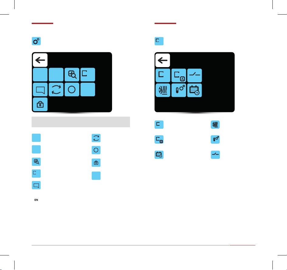
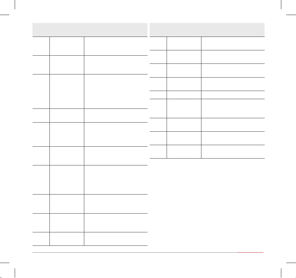
Date setting Restore factory
settings
Zones - name
changes
Antifreeze the room
in a given zone
Zones - device
selection
Selection of
leading sensor
External input
settings
Zone calendar
Time setting Hardware version
Search for devices
BMS settings
Number of zones
Controller lock
Language selection
Enter to the menu after entering the password: 2014
long
press short
press
MAIN MENU ZONE MENU
12-11
11:30
Z
1 2 3
reset
i
12-11 11:30
i BMS
reset
Z
1 2 3
BMS
Z
1 2 3
Z
A B C
Z
EXT.
Z
A B C
Z
EXT.
General settings Settings
Z1 Zone
EN

18
POLSKIENGLISHРУССКИЙNEDERLANDS
alarmswarnings
ALARMS LIST OF ALARMS
02
Z1
03
Z1
05
Z1
06
Z1
01
Z1
04
Z1
0001 - Not connected
Alarms Alarms
Error
code Name Description
1Connection
error
no communication between
DRV and T-box, check connec-
tion and DRV power supply
2Communication
error
communication error between
DRV and T-box, check connec-
tion and software compatibility
3Antifreeze active antifreeze of the room
4DRV group
error
dierent type of device with
the same address is connected,
than was connected during the
search; check binary address set
in DRV and use search button
again
5Temperature
sensor T1
check the temperature sensor
T1
6Temperature
sensor T2
check the temperature sensor
T2
Error
code Name Description
7Temperature
sensor T3
check the temperature sensor
T3
8Temperature
sensor T4
check the temperature sensor
T4
9Temperature
sensor T5
check the temperature sensor
T5
10 Roof fan fuse check the fuse of the roof fan
on the DRV board
11 Fan EC fuse check EC fan fuse on DRV board
12 Fan 3V fuse check the LEO heater fan fuse
on DRV board
13 Roof fan TK roof fan thermal protection
alarm
14 Fan EC not
connected
check the connection of the
EC fan
21
Error
code Name Description
15
Antifreeze heat
recover exchan-
ger ON
antifreeze mode of heat recove-
ry exchanger is on
16
Antifreeze wa-
ter exchanger
ON
water exchanger antifreeze
mode is activated
17 Heater TK
TK protection of the electric
heater was activated; the he-
aters have been turned o, the
fan is running; the alarm resets
automatically when the heaters
cool down
18 Filter work time check lters contamination
level
19 Filter pressure
dirty lter of KM, change the
lter, if pressure switch is not
applied make a bridge (jumper)
between PRDN IN and GND
20 Forcing damper
ON
forcing damper settings
depending on the outside
temperature
21 DUO heater not
connected
no communication between
DRV of fan heater part of
ELiS DUO, check connection
between DRV of air curtain part
and DRV of fan heater part
22 Robur alarm
internal protection of the gas
heater; to reset the alarm, hold
down the alarm icon
23 STB alarm
thermal protection of the gas
heater; to reset the alarm, hold
down the alarm icon
24 STB short circuit STB sensor error; check the STB
temperature sensor
Error
code Name Description
25 Rooftop main-
tenance alarm
maintenance works necessary
26 Rooftop war-
ning alarm
alarm with device operation
support
27 Rooftop fault
alarm
alarm that prevents further
operation of the device
28 Rooftop danger
alarm
alarm that immediately discon-
nects all device functions
90 Time error set T-box clock
91
Internal tempe-
rature sensor
error
damaged internal temperature
sensor in the T-box controller
92 External input:
level 1
external input signal, 1 level
93 External input:
level 2
external input signal, 2 level
94 Lead tempera-
ture sensor
check the leading temperature
sensor

20
POLSKIENGLISHРУССКИЙNEDERLANDS

4343
Table of contents


