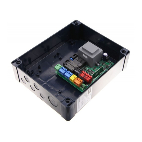
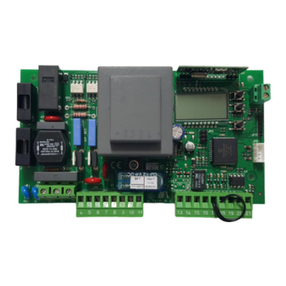
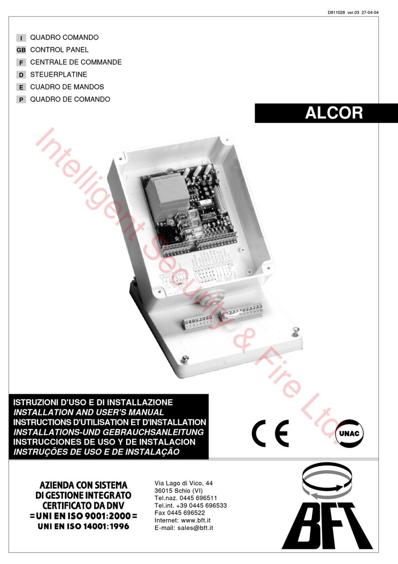
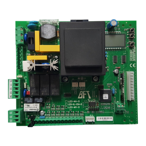
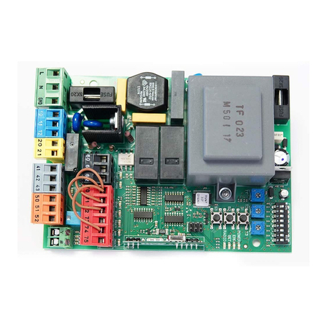
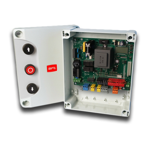
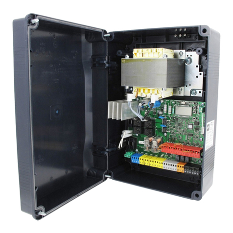
BFT ALCOR AC A User manual

ISTRUZIONI DI INSTALLAZIONE
INSTALLATION MANUAL
INSTRUCTIONS D’INSTALLATION
MONTAGEANLEITUNG
INSTRUCCIONES DE INSTALACION
INSTALLATIEVOORSCHRIFTEN
QUADRO COMANDO
CONTROL PANEL
CENTRALE DE COMMANDE
SELBSTÜBERWACHENDE STEUERUNG
CUADRO DE MANDOS
BEDIENINGSPANEEL
Attenzione! Leggere attentamente le “Avvertenze”all’interno! Caution! Read“Warnings”inside carefully! Attention! Veuillez lire attentivement les Avertissements qui se trouvent à l’intérieur!
Achtung! Bitte lesen Sie aufmerksam die„Hinweise“ im Inneren! ¡Atención¡ Leer atentamente las “Advertencias”en el interior! Let op! Lees de“Waarschuwingen” aan de binnenkant zorgvuldig!
D814011 00100_02 04-12-18
ALCOR AC A

INSTALLAZIONE VELOCE-QUICK INSTALLATION-INSTALLATION RAPIDE
SCHNELLINSTALLATION-INSTALACIÓN RÁPIDA - SNELLE INSTALLATIE
A
BC
JP3
24V
2
1TX1 2
1
RX1
4
5
3
50 51
70 72
DIP3=OFF
LN
L N
0V
50 5251
COM
OPEN
START
NO
NO
60 6261
PHOT
STOP
COM
FAULT 1
BAR
FAULT 2
NC
NC
NC
70 7271 73 7574
230V
max 40W
20 21
Y #
ANT
SHIELD
0,75
0,75
0,75
0,75
*
4x1,5 mm2
*
4x1,5 mm2
10 1211
c
M1
14 1615
c
M2
F1
F2
L10 11 12 14 15 16 20 21 50 51 52
N
60 61 62 70 71 72 73 74 75
Y #
S1
T1 T2
S4
T3
S2
START OPEN
ERR
1 2 3 4 5 6 7 8 9 10
SET
RADIO
STOP PHOT BARFAULT1 FAULT2
24V
24V safe
PREDISPOSIZIONE TUBI, TUBE ARRANGEMENT, PRÉDISPOSITION DES TUYAUX,
VORBEREITUNG DER LEITUNGEN, DISPOSICIÓN DE TUBOS, VOORBEREIDING LEIDINGEN.
Collegamento di 1 coppia di fotocellule non vericate,
per fotocellule vericate vedere pagine seguenti.
Connection of 1 couple of untested photocells,
for tested photocells see the following pages.
Connexion d’une paire de photocellules non vériées,
pour les photocellules vériées consultez les pages suivantes.
Anschluss von einem Paar nicht überprüfter Fotozellen,
für überprüfte Fotozelle siehe die folgenden Seiten.
Conexión de 1 par de fotocélulas no comprobadas,
para fotocélulas comproabdas véanse las siguientes páginas.
Aansluiting van 1 paar niet-geverieerde fotocellen.
Raadpleeg de volgende pagina’s voor geverieerde fotocellen.
Alimentazione
Power supply
Alimentation
Stromversorgung
Alimentación
Voeding
Motore
Motor
moteur
Motor
Eindaanslag
Encoder
Motore
Motor
moteur
Motor
Eindaanslag
Encoder
Alimentazione accessori
Accessories power supply
Alimentation des accessoires
Stromversorgung Zubehör
Alimentación accesorios
Voeding accessoires
Comandi
Commands
Commandes
Bedienelemente
Mandos
Commando’s
Antena
Κεραία
Antena
Антенна
Anténa
Anten
Lampeggiante
Blinker
Clignotant
Warnblinkleuchte
Bombilla
Knipperlicht
Sicurezze
Safety devices
Sécurités
Sicherheitsvorrichtungen
Dispositivos de seguridad
Veiligheden
100mAT (~ 230V)
200mAT (~ 120V)
F1
F2
5 AF (~ 230V)
10 AF (~ 120V)
2 - ALCOR AC A
D814011 00100_02

D
E
START OK
S1
S2
RADIO
x1
S1
S2
RADIO
S1
S2
RADIO
S1
S2
RADIO
1
M1M2 M2M1
2
M2M2M1 M1
10 1211 14 1615
M1
c
M2
c
10 1211 14 1615
M1
c
M2
c
Fisso
Steadily lit
Fixe
Ununterbrochen an
Fijo
Continu
Lampeggio continuo
Continuous ashing
Clignotement continu
Kontinuierliches Blinken
Parpadeo continuo
Continu knipperen
MEMORIZZAZIONE RADIOCOMANDO/MEMORIZING REMOTE CONTROLS/MÉMORISATION RADIOCOMMANDE
ABSPEICHERUNG DER FERNBEDIENUNG /MEMORIZACIÓN DEL RADIOMANDO/MEMORIZAÇÃO DO RADIOCOMANDO
LEGENDA - KEY - LÉGENDE - LEGENDE - LEYENDA - LEGENDA
A
BC
JP3
24V
2
1TX1 2
1
RX1
4
5
3
50 51
70 72
DIP3=OFF
LN
L N
0V
50 5251
COM
OPEN
START
NO
NO
60 6261
PHOT
STOP
COM
FAULT 1
BAR
FAULT 2
NC
NC
NC
70 7271 73 7574
230V
max 40W
20 21
Y #
ANT
SHIELD
0,75
0,75
0,75
0,75
*
4x1,5 mm2
*
4x1,5 mm2
10 1211
c
M1
14 1615
c
M2
F1
F2
L10 11 12 14 15 16 20 21 50 51 52
N
60 61 62 70 71 72 73 74 75
Y #
S1
T1 T2
S4
T3
S2
START OPEN
ERR
1 2 3 4 5 6 7 8 9 10
SET
RADIO
STOP PHOT BARFAULT1 FAULT2
24V
24V safe
ALCOR AC A - 3
D814011 00100_02

50 51 52 70 71 72 73 74 75
24V ~
24V ~
24 VSafe
COM
PHOT
BAR
STOP
FAULT 1
FAULT 2
NC
NC
NC
PHOT
1
2
1
2
3
4
5
51 TX1 RX1
1
2
1
2
3
4
5
52
50 TX1 RX1
1
2
1
2
3
4
5
TX1 RX1
1
2
1
2
3
4
5
TX2 RX2
1
2
1
2
3
4
5
TX1 RX1
1
2
1
2
3
4
5
TX1 RX1
1
2
1
2
3
4
5
TX1 RX1
1
2
1
2
3
4
5
TX2 RX2
1 PHOT / 1 PHOT CL
1 PHOT / 1 PHOT CL
2 PHOT / 2 PHOT CL
BAR 8K2
50
52
50
52
50
51
50
51
50
51
50
51
50
70
72
70
72
73
70
70
72
73
BAR
Bar 1
1
2
3
4
5
6
Bar 1
1
2
3
4
5
Bar 2
1
2
3
4
5
Bar 1
1
2
3
4
5
6
6
6
Bar 1
1
2
3
4
5
6
Bar 1
1
2
3
4
5
Bar 2
1
2
3
4
5
Bar 1
1
2
3
4
5
6
6
6
1 BAR/ 1BAR CL
51
51
50
51
50
51
50
52
52
52
74
70
74
70
75
74
70
51
50
70
75
70
74 8,2Kohm 5%
SAFETY EDGE SAFETY EDGE
DIP2 OFF
DIP4 OFFDIP4 ON
DIP2 ON
DIP3 OFFDIP3 ON
100
195
237
1 BAR TEST/ 1 BAR CL TEST
2 BAR TEST/ 2 BAR CL TEST
BAR 8K2/ BAR CL 8K2
F
G
4 - ALCOR AC A
D814011 00100_02

INSTALLATION MANUAL
1) GENERAL INFORMATION
The ALCOR AC A control panel comes with standard factory settings.
Any change must be set by means of the TRIMMER and DIP SWITCH settings.
Its main features are:
- Checking of 2 single phase motors
- Separate inputs for safeties
- Rolling-code in-built radio receiver.
The board has a terminal strip of the removable kind to make maintenance or re-
placementeasier.Itcomeswithaseriesofprewiredjumperstomaketheinstaller’s
job on site easier. The jumpers concern terminals: 70-71, 70-72, 70-74. If the
above-mentioned terminals are being used, remove the relevant jumpers.
TESTING
The ALCOR AC A panel controls (checks) the start relays and safety devices
(photocells) before performing each opening and closing cycle.
If there is a malfunction, make sure that the connected devices are working
properly and check the wiring.
2) TECHNICAL SPECIFICATIONS
Power supply 110-120V 50/60Hz
220-230V 50/60 Hz
Panel dimensions Fig. F
Low voltage/mains insulation > 2MOhm 500V
Operating temperature range -20 / +50°C
Dielectric rigidity mains/LV 3750V~ for 1 minute
Accessories power supply 4V~ (demand max. 0,2A)
AUX 0 - Flashing
Contact powered
120V~ 40W max
230V~ 40W max
Fuses Fig. C
Built-in Rolling-Code
radio-receiver frequency 433.92MHz
Setting of parameters and logics TRIMMER + DIP SWITCH
Max. n° of remotes that can be
memorized 63
Maximum power 750W
Maximum work time 90s
Usable transmitter versions:
All ROLLING CODE transmitters compatible with .
3) TUBE ARRANGEMENT Fig. A
Install the electrical system referring to the standards in force for electrical systems
CEI 64-8, IEC 364, harmonization document HD 384 and other national standards.
4) TERMINAL BOARD WIRING Fig. C
For the electric diagram and the cross section of the cables refer to the
manual of the actuator.
Once suitable electric cables have been run through the raceways and the auto-
mated device’s various components have been fastened at the predetermined
points,thenext stepistoconnectthem asdirectedand illustratedinthe diagrams
containedin therelevantinstruction manuals.Connect thelive, neutral andearth
wire (compulsory).
WARNINGS - When performing wiring and installation, refer to the standards
in force and, whatever the case, apply good practice principles. Wires carrying
dierent voltages must be kept physically separate from each other, or they must
be suitably insulated with at least 1mm of additional insulation.
Wires must be secured with additional fastening near the terminals, using devi-
ces such as cable clamps. All connecting cables must be kept far enough away
from dissipaters.
WARNING! For connection to the mains power supply, use a multicore cable
with a cross-sectional area of at least 3x1.5mm2of the kind provided for by
the regulations in force.
To connect the motors, use a cable with a cross-sectional area of at least
1.5mm2of the kind provided for by the regulations in force.
The cable must be type H05RN-F at least.
5) SAFETY DEVICES
Note: only use receiving safety devices with free changeover contact.
5.1) TESTED DEVICES Fig.G
5
.2)CONNECTION OF 1 PAIR OF NON-TESTED PHOTOCELLS FIG. B
WARNING!
The values of the impact force according to EN 12453 are only observed with
the use of safety edges (active) connected to the board.
6)MEMORIZING TRANSMITTERS FIG. D
7) REVERSING THE OPENING DIRECTION (Fig.E)
8)ADJUSTMENT PROCEDURE
-Before turning the unit on, check electrical connections.
- Set the following parameters:
Automatic Closing Time,
Phase shift timing while closing
- Set the logics.
WARNING! Incorrect settings can result in damage to property and injury
to people and animals.
WARNING: Check that the force of impact measured at the points pro-
vided for by standard EN 12445 is lower than the value laid down by
standard EN 12453.
KEYS
KEYS Description
S1 Add Start Key
associates the desired key with the Start command.
S2 Add Pedestrian Key
associates the desired key with the pedestrian command.
S2
>5s Conrms the changes made to parameter settings and operating
S1+S2
>10s Erase List
WARNING! Erases all memorized transmitters from the
receiver’s memory.
LED INDICATORS:
POWER Steadily lit: - Mains power on - Board powered - Fuses intact
START Lit: START input activated
OPEN Lit: OPEN pedestrian input activated
STOP Unlit: STOP input activated
PHOT Unlit: PHOT photocell input activated
FAULT 1 PHOT input safety device test input diagnostics
BAR Unlit: BAR safety edge input activated
FAULT 2 BAR input safety device test input diagnostics
ERR Unlit: no error
LIT: see error diagnostics table
RADIO
(GREEN)
Unlit: remote programming not active
Radio LED only ashing: Remote programming active, waiting for
hidden key.
Flashing in sync with Set LED: Transmitter deletion in progress
Lit: remote programming active, waiting for desired key.
Lit 1s: Radio receiver channel activated
SET Lit: see error diagnostics table
Flashing in sync with Radio LED: Transmitter deletion in progress
TABLE ERR
Led ERR
Lit slow ashing fast ashing
Led SET
Unlit
Photocell test,
Costa o Costa 8k2
failed
- Check photocell
connection and/
or logic settings
Lit
Reverse due to
obstacle - Ampe-
rostop
- Check for obsta-
cles in path
slow
ashing
Test hardware
card error
- Check the
connection to the
motor
- Hardware pro-
blems to the card
(contact technical
assistance)
Changed settings
and/or Operating
logics press S2 for
5s to conrm.
8 - ALCOR AC A
D814011 00100_02
INSTALLATION MANUAL
ENGLISH
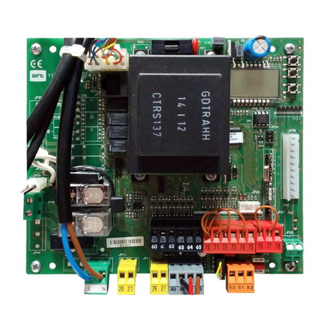
Terminal Denition Description
Power
supply
LLINE Single-phase power supply
NNEUTRAL
Motor
10 START + CONDENSER
Motor and condenser connection
11 COM
12 START + CONDENSER
14 START + CONDENSER Connection between motor and capacitor 2.
Note: if T3=0 do not connect any cable to clamps 14-15-16
15 COM
16 START + CONDENSER
Aux
20 AUX 0 – POWERED CONTACT
230V (N.O.) (40W MAX) Exit due to FLASHING LIGHT
Contact stays closed while leaves are operating.
21
Accessories
power supply
50 0V- Accessories power supply output.
51 24V+
52 24 Vsafe+
Tested safety device power supply output (photocell transmitter and safety edge transmitter).
Output act ive only during operating cycle.
Commands
60 Common START and OPEN inputs common
61 START START command button (N.O.).
Operation according to “Residential / apartment building operation”logic
62 OPEN
OPEN command button (N.O.).
Gate opened with this command. If the input stays closed, the leaves stay open until the
contact is opened.
When the contact is open, the automated device closes following the TCA time, where
activated.
Safety devices
70 Common STOP, PHOT and BAR inputs common
71 STOP The command stops movement. (N.C.)
If not used, leave jumper inserted.
72 PHOT (*) PHOTOCELL input (N.C.).
Operation according to “PHOTOCELL/PHOTOCELL DURING CLOSING”logic. If not used, leave
jumper inserted.
73 FAULT 1 Test input for safety devices connected to PHOT.
74
BAR /
BAR CL /
BAR TEST /
BAR CL TEST /
BAR 8K2 /
BAR CL 8K2
(*)
Safety edge input (N.C.).
If not used, leave jumper inserted
BAR/8K2
dip Safety edge
check
dip
Safety edge
operation
dip
OFF OFF OFF NC input, no verication, reversal while
opening and closing (BAR)
OFF OFF ON NC input, no verication, reversal only
when closing, stop when opening (BAR
CL)
OFF ON OFF NC input, with verication, reversal
while opening and closing (BAR TEST)
OFF ON ON NC input, with verication, reversal only
when closing, stop when opening (BAR
CL TEST)
ON OFF OFF 8K2 input, reversal when opening and
closing (BAR 8K2)
ON OFF ON 8K2 input, reversal only when closing,
stop when opening (BAR CL 8K2)
75 FAULT 2 Test input for safety devices connected to BAR / BAR CL
Antenna
YANTENNA Antenna input.
Use an antenna tuned to 433MHz. Use RG58 coax cable to connect the Antenna and Receiver.
Metal bodies close to the antenna can interfere with radio reception. If the transmitter’s
range is limited, move the antenna to a more suitable position.
#SHIELD
(*) If“D” type devices are installed (as dened by EN12453), connect in unveried mode, foresee mandatory maintenance at least every six months.
(*) In the European Union, apply standard EN 12453 for force limitations, and standard EN 12445 for measuring method.
TABLE “A” -PARAMETERS
Any modication of parameters/logics must be conrmed by pressing S2 > 5s
TRIMMER Parameter +
min. +
max. +
default
Description
T1 Automatic
closing time [s] 0 120 0 Waiting time before automatic closing.
NOTE: Set to 0 if not used.
T2 Work time [s] 5 90 50% Adjusts the motors’work time, lapsing which they will stop.
T3 Motor 1 closing
delay time [s] 0 25 25% Motor 1 closing delay time with respect to motor 2.
NOTE: set 0 for single motor operations (leaf 1).
ALCOR AC A - 9
D814011 00100_02

INSTALLATION MANUAL
TABLE “B” -LOGICS
Any modication of parameters/logics must be conrmed by pressing S2 > 5s
DIP Logic Default Cross out
setting used Description
1Transmitter
programming ON
ON
Enables wireless memorizing of transmitters:
1- Press in sequence the hidden key and normal key (T1-T2-T3-T4) of a transmitter that has already been
memorized in standard mode via the radio menu.
2-
Press within 10 sec. the hidden key and normal key (T1-T2-T3-T4) of a transmitter to be memorized.
The receiver exits programming mode after 10 sec.: you can use this time to enter other new transmitters.
This mode does not require access to the control panel.
IMPORTANT: Enables the automatic addition of new transmitters, clones and replays.
OFF
Disables wireless memorizing of transmitters and automatic addition of clones.
Transmitters are memorized only using the relevant Radio menu or automatically with replays.
IMPORTANT: Disables the automatic addition of new transmitters and clones
2 BAR / 8K2 OFF
ON Input congured as Bar 8k2 (Fig.G). Input for resistive edge 8K2.
The command reverses movement for 1 sec.
OFF Input congured as Bar, safety edge (Fig.G).
The command reverses movement for 1 sec..
3Photocell input
check OFF ON Enable safety check on the PHOT input. (Fig.G)
OFF Safety check on PHOT input not enabled. (Fig.G)
4 Edge input check OFF ON Enable safety check on the BAR input. (Fig.G)
OFF Safety check on BAR input not enabled. (Fig.G)
5Photocells
during closing OFF
ON In the event beam is broken, photocell operation is disabled during opening. During closing, move-
ment is reversed immediately.
OFF When beam is broken, photocells are active during both opening and clo-
sing. When beam is broken during closing, movement is reversed only once the
photocell is cleared.
6Safety edge
input operation OFF ON Safety edge with active reversal only when closing, when opening the movement stops
OFF Safety edge with active reversal in both directions
7 Fast closing OFF ON Closes 3 seconds after the photocells are cleared before waiting for the set TCA to elapse.
OFF Logic not enabled
8
Residential /
apartment
building
operation
OFF
ON
Sets the
automation type
of operation:
ON = Apartment building
Reaction to the START input (wired or radio):
Residential Apartment building
CLOSED Opens Opens
WHILE CLOSING Stops Opens
OPEN Closes Closes
WHILE OPENING STOPS + TCA No eect
AFTER STOP Opens Opens
Reaction to the OPEN input (wired):
Residential Apartment building
CLOSED Opens Opens
WHILE CLOSING Opens Opens
OPEN Keep open + TCA Keep open + TCA
WHILE OPENING No eect No eect
AFTER STOP Opens Opens
Reaction to the PEDESTRIAN input (radio):
Residential Apartment building
CLOSED Opens partially Opens partially
WHILE CLOSING Stops Opens partially
OPEN Closes Closes
WHILE OPENING STOPS + TCA No eect
AFTER STOP Opens partially Opens partially
OFF OFF = Residential
9Hammer during
opening OFF ON Before opening completely, the gate pushes for approx. 2 seconds as it closes. This allows the sole-
noid lock to be released more easily.
IMPORTANT - Do not use this function if suitable mechanical stops are not in place.
OFF Logic not enabled
10 Stop
maintenance OFF ON
If motors stay idle in fully open or fully closed position for more than one hour, they are switched on
in the direction of the stop for approx. 3 seconds. This operation is performed every hour.
NB: In hydraulic motors, this function serves to compensate a possible reduction in the volume of oil
due to a drop in temperature during extended pauses, such as during the night, or due to internal
leakage.
IMPORTANT - Do not use this function if suitable mechanical stops are not in place.
OFF Logic not enabled
10 - ALCOR AC A
D814011 00100_02
www.bftme.ae
Table of contents
Other BFT Control Panel manuals