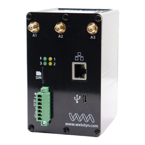
Flexitron Webdyn WebdynEasy LoRaWAN User manual

WebdynEasy LoRaWAN
LoRaWAN gateway with external or
embedded server
USER MANUAL

2
USER MANUAL - WebdynEasy LoRaWAN
Version .1
1
Glossary .............................................................................................................. 4
2
Notes on this manual........................................................................................... 6
2.1
Scope ........................................................................................................... 6
2.2
Target group................................................................................................. 6
2.3
Product and accessory references............................................................... 6
2.3.1
Safety instructions................................................................................... 7
2.4
Regulations .................................................................................................. 8
3
General presentation........................................................................................... 9
3.1
The LoRaWAN protocol ............................................................................... 9
3.2
The hub ...................................................................................................... 10
3.2.1
General description............................................................................... 10
3.2.1.1
Exterior........................................................................................... 10
3.2.1.2
Interior ............................................................................................ 10
3.2.2
Technical Specifications ....................................................................... 13
3.2.2.1
General specifications .................................................................... 13
3.2.2.2
Technical specifications.................................................................. 14
3.2.2.3
LoRa specifications ........................................................................ 15
3.2.2.4
Software specifications................................................................... 15
4
Installation and Maintenance............................................................................. 16
4.1
Unpacking .................................................................................................. 16
4.1.1
Product contents................................................................................... 16
4.1.2
Hub identification .................................................................................. 16
4.2
Assembly.................................................................................................... 17
4.2.1
Opening/closing the box ....................................................................... 18
4.2.2
Wall mounting ....................................................................................... 18
4.2.3
Cellular Network.................................................................................... 18
4.2.3.1
Antenna.......................................................................................... 18
4.2.3.2
SIM card......................................................................................... 19
4.2.4
LoRa ..................................................................................................... 20
4.2.5
Connection............................................................................................ 21
4.2.5.1
Power supply.................................................................................. 21
4.2.5.2
RS485/RS422 Bus ......................................................................... 22
4.2.5.3
Ethernet.......................................................................................... 23
5
Configuration ..................................................................................................... 26
5.1
Embedded web interface............................................................................ 26
5.1.1
Hub connectivity.................................................................................... 27
5.1.1.1
Modem ........................................................................................... 27
5.1.1.2
Ethernet.......................................................................................... 28
5.1.1.3
FTP ................................................................................................ 29
5.1.1.4
NTP ................................................................................................ 30
5.1.1.5
Upload............................................................................................ 30
5.1.2
LoRaWAN............................................................................................. 31
5.1.2.1
Packet Forwarder ........................................................................... 31
5.1.2.2
LoRaWAN server ........................................................................... 32
5.1.3
System.................................................................................................. 34
CONTENTS

3
USER MANUAL - WebdynEasy LoRaWAN
Version .1
5.1.4
Alarms................................................................................................... 35
5.1.5
Schedules ............................................................................................. 36
5.1.6
Modbus ................................................................................................. 40
5.1.7
Run actions........................................................................................... 44
5.1.7.1
Remote server connection request. Request ................................. 44
5.1.7.2
Reboot request: Reboot ................................................................. 45
5.1.7.3
Log download: Download logs........................................................ 45
5.1.7.4
Manual time set: Set time............................................................... 45
5.1.7.5
System file upload: File upload....................................................... 46
6
Operation........................................................................................................... 47
6.1
The remote server...................................................................................... 47
6.1.1
The FTP server ..................................................................................... 47
6.1.1.1
Configuration .................................................................................. 47
6.1.1.2
Operation........................................................................................ 48
6.1.1.3
File Format ..................................................................................... 49
6.2
The configuration........................................................................................ 49
6.3
The data ..................................................................................................... 51
6.4
Alarms ........................................................................................................ 51
6.5
Commands................................................................................................. 52
6.5.1
“reboot" command................................................................................. 53
6.5.2
“Factory” command............................................................................... 54
6.5.3
“Update" command ............................................................................... 54
6.5.4
“connect" command .............................................................................. 54
6.5.5
“Status" command................................................................................. 54
6.5.6
“log" command...................................................................................... 55
6.5.7
“modbus" command.............................................................................. 55
7
Update............................................................................................................... 57
7.1
Local........................................................................................................... 57
7.2
Remote....................................................................................................... 57
8
Support.............................................................................................................. 58
9
Appendix A: XML configuration file variables .................................................... 59

4
USER MANUAL - WebdynEasy LoRaWAN
Version .1
1Glossary
Name Description
AB Activation By ersonalization
ABP activation forces to have the DevAddr and the security key for the
peripheral hard-coded in the product. This strategy may seem simpler
because the join procedure does not need to be known, but it has security
disadvantages.
ADR Adaptive Data Rate
A data rate and radio transmission power optimisation mechanism. It is used
to optimise battery consumption.
A N Access oint Name
The name of the access point the gateway uses to connect to the Internet via
a mobile connection.
AppEUI The EUI Application is a unique application identifier issued by the IEEE
organisation (EUI-64). It is only used in OTAA mode and is used to get the
server keys during the JOIN.
AppKEY The Application Key is product specific. It is only used in OTAA mode and is
used to get the server keys during the JOIN.
AppSKey The Application Session Key is product specific and is used for end to end
application data encryption. It is required in ABP mode and is calculated
automatically by the server during the JOIN in OTAA mode.
Data Rate The Data Rate is defined by a digit from to 5 and sets the modulation type,
the Spreading Factor and the bandwidth used.
DevEUI Device EUI
The unique identifier issued by the IEEE organisation (EUI-64).
Device
Address
32 bit device identifier that is used to uniquely identify the product on the
LoRaWAN server. It is required in ABP mode and is supplied automatically by
the server during the JOIN in OTAA mode.
Ftp File Transfer rotocol
Communication protocol used to exchange files over a TCP/IP network.
HTT HyperText Transfer rotocol
Client-server communication protocol developed for the Web.
I Internet rotocol
Message protocol in charge of addressing and sending TCP packets over the
network.
LoRa LoRa is radio modulation including the physical connection and the physical
layer in the OSI model
LoRaWAN LoRaWAN is a transmission protocol that uses LoRa modulation.
MD5 Message Digest 5
Cryptographic hash function used to obtain a file's digital imprint.

5
USER MANUAL - WebdynEasy LoRaWAN
Version .1
Modbus Modbus is a communication protocol routinely used by industry to dialogue
with industrial equipment over a network.
NT
Network Time rotocol
Protocol used to synchronise the local hub clock with a time reference via a
computer network.
NwkSKey The Network Session Key is product specific and is used for end to end
LoRaWAN network data encryption. It is required in ABP mode and is
calculated automatically by the server during the JOIN in OTAA mode.
OTAA Over The Air Activation
OTAA activation is the preferred and most secure method for connecting to
the LoRaWAN network. The product runs a join procedure with the network
during which a dynamic DevAddr is assigned and security keys are brokered
with the product.
DIN rail Standard 35 mm metal rail used in Europe in industrial control equipment in
racks
RTU RTU mode is an RS422/485 hard-wired bus for Modbus.
Spreading
Factor (SF)
The spreading factor is the length of the sent frames. The more the signal is
spread, the lower the speed. However it increases the product range.
TC Transmission Control rotocol
An Internet-based connection-oriented protocol that provides data packet
segmenting services that the IP protocol sends over the network. This
protocol provides a reliable data transfer service. See also IP.
TC /I Transmission Control rotocol/Internet rotocol
A set of network protocols that provide interconnection services between
computers of different hardware architectures and operating systems.
TCP/IP includes standards for communication between computers and
conventions for network interconnection and routing.
UD User Datagram rotocol
Non connection-oriented protocol of the TCP/IP model transport layer. This
protocol is very simple because is does not provide error checks (it is not
connection-oriented...).
XML Extensible Markup Language
Generic tagging computer metalanguage. The purpose of XML is to facilitate
the automated exchange of complex content between heterogeneous
information systems.
XSD XML Schema Definition
File used to validate XML tags and data in an XML file.

6
USER MANUAL - WebdynEasy LoRaWAN
Version .1
2Notes on this manual
This guide describes the hub assembly, installation and configuration as well as its remote
operation.
2.1 Scope
This technical description is valid for WebdynEasy LoRaWAN hubs from hardware version V1
and software version V1. onwards.
2.2 Target group
This guide is intended for WebdynEasy LoRaWAN hub installers and users, but also for people
using our Sens’RF LoRaWAN sensors.
2.3 Product and accessory references
LoRaWAN hub:
roduct references Versions
WG 61 -A 1 WebdynEasy LoRaWAN
LoRaWAN Webdyn compatible sensor:
roduct references Description
WG 3 7-D 1-EU Sens'RF-LoRaWAN-Pulse (no external power supply)
WG 3 7-D 2-EU Sens'RF-LoRaWAN-Pressure Humidity and Temperature (no
external power supply)

7
USER MANUAL - WebdynEasy LoRaWAN
Version .1
WG 3 7-D 3-EU Sens'RF-LoRaWAN-TIC (no external power supply)
WG 3 7-D 8-EU Sens'RF-LoRaWAN-Analog ( -1 V/4-2 mA) (no external
power supply)
WG 3 7-D11-EU Sens'RF-LoRaWAN-Pulse (with external power supply)
WG 3 7-D12-EU Sens'RF-LoRaWAN-Pressure Humidity and Temperature
(with external power supply)
WG 3 7-D13-EU Sens'RF-LoRaWAN-TIC (with external power supply)
WG 3 7-D18-EU Sens'RF-LoRaWAN-Analog ( -1 V/4-2 mA) (with external
power supply)
2.3.1 Safety instructions
It is imperative to follow all the safety instructions in this guide.
Failure to follow these instructions can damage equipment and endanger people.
Electric connection:
•All wiring work must be carried out by a specialised qualified electrician.
•Please follow all the safety instructions featured in the equipment
documentation.
The WebdynEasy product can be damaged by electrostatic discharges (ESD)
When the equipment is open, do not carry out any operations other than those
described in this manual. Avoid any contact with the components.
Class 3 equipment: the device operates on safety extra-low voltage (SELV) (5 V
maximum). The voltage reduction must be obtained using a safety transformer
providing safe galvanic isolation between primary and secondary.
Do not install the equipment near a heat source or at a height greater than 2m.
To clean the product, only use a slightly damp cloth to gently clean and wipe the
surfaces.
Never use aggressive chemical agents or solvents that could alter the plastic
material or corrode the metal parts.

8
USER MANUAL - WebdynEasy LoRaWAN
Version .1
To optimise radio and cellular modem reception sensitivity, it is imperative to leave
2 cm free space around the antennas.
2.4 Regulations
The product complies with the European directives according to the EU Declaration of
Conformity available from Webdyn or on website: www.webdyn.com
Recycling:
The European directives enacted into national law covering battery waste and
electric and electronic equipment provide the framework for the actions needed
to limit the negative impact of the product's end of life.
These products are collected separately. Use an authorised battery collection and processing
centre or contact Webdyn.

9
USER MANUAL - WebdynEasy LoRaWAN
Version .1
3General presentation
The WebdynEasy LoRaWAN hub is part of a line of Webdyn hubs specific to wireless networks.
The hub’s main function is to be a LoRaWAN gateway to create a LoRaWAN network and
collect the data from the different LoRa sensors deployed nearby. The LoRaWAN gateway has
2 running modes:
•Packet Forwarder
•Packet Forwarder with embedded LoRaWAN server
The hub is also used to communicate with Modbus devices in IP or RTU mode.
Principle diagram for a complete LoRaWAN solution
3.1 The LoRaWAN protocol
LoRaWAN is a communication protocol that uses LoRa modulation. This communication
protocol uses several radio bands (ISM) that are available in the 868 MHz range in Europe
without a licence.
In a LoRaWAN network, the radio modules are not paired to a single base station. The data
they send is relayed by multiple base stations. Each one sends the information received from
a radio module to the management server via a gateway. The intelligence and complexity are
Packet Forwarder with
embedded server
Sens’RF
or
LoRa sensor
Gateway
LoRa server
Customer server
LoRaWan
Packet Forwarder

1
USER MANUAL - WebdynEasy LoRaWAN
Version .1
located on the server which manages data redundancy, integrity checks, receipt confirmation
and the adaptation of the sensor data rate and emission power.
3.2 The hu
The purpose of the hub is to collect LoRaWAN and/or Modbus data and regularly send it to a
remote server (IS) using Ethernet or 3G/4G.
3.2.1 General description
3.2.1.1 Exterior
Box front face:
3.2.1.2 Interior
Interior of the box:
External power supply
cable gland
•Cap (by default)
•Cable gland for
3G/4G external
antenna (option)
•Ventilation (by default)
•Cable gland for
RS485/RS422 (option)
•Cap (by default)
•Cable gland for
external LoRa RF
antenna (option)

11
USER MANUAL - WebdynEasy LoRaWAN
Version .1
SIM card holder
Reset button
RJ45 connector and LEDs
BLE Bluetooth (future use)
Request button (identified FUNCTION on the board)
1
2
3
4
5
1
2
3
4
5
6
7
8
9
1
11
12
13
14
15

12
USER MANUAL - WebdynEasy LoRaWAN
Version .1
LoRa RF radio SMA antenna
Box output for the LoRa RF radio external antenna (option)
Box RS485/422 output
1 RS485/422 port
Indicators:
-LED 8: Power
-LED 3: Modem
-LED 1: CPU
-LED 7: LoRa
Box output for external power supply
Terminal block for external 12/24V power supply
Box output for the 3G/4G modem external antenna (option)
3G/4G Modem SMA Antenna
Mini-USB connector (reserved)
Indicators:
LED Description
Power Lights when the product is powered
CPU Lights depending on the CPU activity
LoRa Off by default and flashes to indicate LoRaWAN radio traffic
6
7
8
9
10
11
12
13
14
15

13
USER MANUAL - WebdynEasy LoRaWAN
Version .1
Modem Lights when the Modem sets up an IP connection
Lights for 1 second on receipt of a text message
Following a long press on the Request button, it indicates the received
signal level (RSSI) using a number of flashes ( to 5 times)
– signal power ≤ -112 dBm
1 – signal power between -111 dBm and -96 dBm
2 – signal power between -96 dBm and -81 dBm
3 – signal power between -81 dBm and -66 dBm
4 – signal power between -66 dBm and -51 dBm
5 - signal power > -51 dBm
Buttons:
Button Description
Request Short press (less than 2 seconds) => Connection request
Long press (more than 2 seconds) => Displays the Modem signal reception
level (see Modem LED)
3 successive long presses in less than 15 seconds => Return to factory
settings
Reset Hub reboot (Hard Reset)
Never press the RESET button 7 times in less than 3 seconds. This would switch
the hub to a special mode that prevents it from starting. To exit the mode, a new
hub RESET is required.
End users must make sure their installation using remote antennas meets
applicable EMC standards.
3.2.2 Technical Specifications
3.2.2.1 General specifications

14
USER MANUAL - WebdynEasy LoRaWAN
Version .1
Parameters Values
External power supply +12/24V DC from an external power supply
Consumption 1 Watts maximum
lash memory 5 Mb (shared between compressed and
uncompressed files)
Dimensions 16 x 15 x 55 mm
Box ASA IP67 box
Weight .45 kg
Operating temperature -2 °C/+55°C
Storage temperature -2 °C/+7 °C
Humidity 25 - 75 %
Pollution rating 2
Certification RED
ROHS
REACH
Regulation : CE marking created in the framework
of European technical harmonisation
legislation. It is mandatory for all products
covered by one or more European
regulatory texts (directives or regulations)
: Symbol indicating that the waste must
be collected via a specific channel and must
not be disposed of as household waste.
: Symbol indicating that the product
must be recycled.
3.2.2.2 Technical specifications
Parameters Values
LoRa radio interface 863MHz -87 MHz
Modem interface 3G: HSPA+, UMTS (B1, B8)
4G: Cat-1, Bands B1, B3, B7, B8, B2 , B28
-Serial interface 1 RS422/RS485 Modbus RTU port
Ethernet network interface 1 /1 Mbit/s
RF band Emission frequencies Max Power
3G 2100MHz (B1) 192 –198 MHz 23 dBm class 3b

15
USER MANUAL - WebdynEasy LoRaWAN
Version .1
3G 900 MHz (B8) 88 –915 MHz 23 dBm class 3b
4G 2100 MHz (B1) 192 –198 MHz 23 dBm class 3
4G 1800 MHz (B3) 171 –1785 MHz 23 dBm class 3
4G 2600 MHz (B7) 25 –257 MHz 23 dBm class 3
4G 900MHz (B8) 88 –915 MHz 23 dBm class 3
4G 800MHz (B20) 832–862 MHz 23 dBm class 3
4G 700MHz (B28) 7 3–748 MHz 23 dBm class 3
3.2.2.3 LoRa specifications
Parameters Values
Channels 8 simultaneous channels:
•863-87 MHz (Europe)
•865-867 MHz (India)
Max sensitivity -141dBm (125kHz in SF12)
Supported DataRate DR -DR5
Supported Bandwidth 125/25 kHz
Max TX power +14dBm
Activation mode ABP or OTAA
Default frequencies Europe: 867.1 MHz, 867.3 MHz, 867.5 MHz,
867.7 MHz, 867.9 MHz, 868.1 MHz, 868.3
MHz, 868.5 MHz
India: 865. 625 MHz, 865.4 25 MHz,
865.985MHz
3.2.2.4 Software specifications
Parameters Values
LoRaWAN server -LoRaWAN V1. .2 class A protocol
-1 LoRaWAN sensors supported
-1 gateways supported
Modbus Monitoring in RTU and TCP mode

16
USER MANUAL - WebdynEasy LoRaWAN
Version .1
4Installation and Maintenance
4.1 Unpacking
4.1.1 roduct contents
Start by checking the contents before starting any installation work. If there are missing or
damaged items, contact Webdyn support. (see section8: “Support”)
WebdynEasy LoRaWAN hub
(Ref.: WG 61 -A 1)
The following are shipped with the hub:
•a curved SMA antenna for the modem (internal)
•a curved SMA antenna for the radio (internal)
4.1.2 Hub identification
Identification label:
The WebdynEasy LoRaWAN hub can be identified from its identification label located on the
box.

17
USER MANUAL - WebdynEasy LoRaWAN
Version .1
This label features:
•Product name (WG 61 -A 1)
•The date of manufacture (in WW/YY format at the top right)
•The serial number in character and 128 barcode format.
•The MAC (Ethernet) address in character format.
Software version.
The software version can be found on the hub web interface. The software version is given on
the “Overview” tab (See section 5.1.1: “Hub connectivity”).
4.2 Assem ly
It is important to comply with the environment conditions described in section 3.2.2.1:
“General specifications” before installing, as well as the following conditions:
•
Protect the product from dust, moisture, aggressive substances and corrosion.
•
The distance between the hub and Modbus equipment must not exceed the
maximum authorised distance for the corresponding interface type (RS485 or RS422)
(See section 4.2.5.2: “RS485/RS422 Bus”).
•
If the Modem connection is used, make sure there is optimum reception when
installing. Check the RSSI which is available on the embedded web page (See section
5.1.1.1: “Modem”)
Identification label
WG 61 -A 1 WW/YY
MAC: : 5:F3: : :
S/N:
XXXXXXXXXXXX
Product CE label
Top view Underside view

18
USER MANUAL - WebdynEasy LoRaWAN
Version .1
To optimise Modem and LoRa radio reception sensitivity, it is essential to leave 2
cm free space around the antennas.
4.2.1 Opening/closing the box
Follow these steps to open the hub box:
If the box is wall-mounted:
1. Open the 2 doors on the front panel.
2. Unscrew the 4 wall mounting screws in the recesses under the doors.
Then follow these steps:
1. Unscrew the 4 screws behind the box.
2. Remove the cover
Follow these steps to close the hub box:
1. Place the cover on the box base, make sure the seal is properly fitted.
2. Screw in the 4 screws on the back of the box.
4.2.2 Wall mounting
The WebdynEasy can be wall-mounted. Before wall-mounting, first close the box (see section
4.2.1: “Opening/closing the box”)
Screws and anchors are not included in the kit. You must choose the correct type
of screw for the type of wall you are fixing the hub to.
(4 mm diameter screw, minimum length 25 mm)
Follow the steps below to fix the hub to a wall:
1. Open the 2 doors on the front panel.
2. Screw the 4 wall mounting screws into the recesses under the doors.
3. Close both doors on the front.
4.2.3 Cellular Network
The WebdynEasy hub includes a 3G and 4G network compatible modem.
4.2.3.1 Antenna
The hub has a female SMA connector labelled "4G" on the board to connect a modem
antenna. The product is delivered with an internal antenna. An external antenna can be
connected to the product. To do this, unscrew the cap on the box and fit a M16*1.5 cable
gland (not included).

19
USER MANUAL - WebdynEasy LoRaWAN
Version .1
If the WebdynEasy hub were to be installed in a metal box or in a location that
does not have proper signal reception, the use of a remote antenna is strongly
recommended.
Be careful to use an antenna compatible with the connector and frequencies used.
End users must make sure their installation using remote antennas meets
applicable EMC standards.
4.2.3.2 SIM card
To use the 3G or 4G modem connection to allow the hub to communicate with the remote
server, the box must be opened (see section4.2.1: “Opening/closing the box") and a mini SIM
card inserted into the SIM card housing inside the hub.
The hub is compatible with all market operators as well as with all mini SIM 2FF 25 x 15mm
format SIM cards.
To check that the WebdynEasy is operating properly, insert a SIM card with the following
specifications:
•Possibility of receiving and sending text messages,
•3G and 4G communication included.
Internal Antenna External antenna
Cap
External antenna
cable gland
Internal antenna
SMA connector

2
USER MANUAL - WebdynEasy LoRaWAN
Version .1
To insert the SIM card into the product, slide the holder flap to the right (in the OPEN
direction). Slide the SIM card into the flap. Then close the flap by sliding it to the left (in the
LOCK direction)
Webdyn does not supply any SIM cards. Please contact an M2M operator that
supports the 3G and LTE-M network.
Please contact your SIM card provider to find out what information to enter to
configuration the modem.
By default, the hub configuration does not request a PIN code (PIN Mode: Off). If you want to
enable the hub PIN code, it is preferable to configure it before the SIM card is installed. (see
section 5.1.1: Hub connectivity)
There are three possibilities:
•The PIN code is disabled: modem communication is active.
•The PIN code is enabled and the entered PIN code is correct: modem communication
is active.
•The PIN code is enabled and the entered PIN code is incorrect: modem communication
is in error.
If the SIM card has an enabled PIN code and it is incorrect the first time the hub is
started , it will be blocked after 3 attempts.
It can be unlocked using a mobile phone using the PUK code provided by the
operator.
4.2.4 LoRa
The hub has a female SMA connector labelled "RF" on the board to connect a radio antenna.
The product is delivered with an internal antenna. An external antenna can be connected to
SIM card
This manual suits for next models
1
Table of contents
Other Flexitron Gateway manuals
Popular Gateway manuals by other brands

Nokia
Nokia 100i - IP VPN - Gateway installation guide

Rosslare
Rosslare AY-M26 Installation and configuration manual

Avaya
Avaya Media Gateway G250 Installation and upgrade guide

Matrix Telecom
Matrix Telecom SARVAM UMG quick start

D-Link
D-Link DVG-3016S user manual
Fortinet
Fortinet FortiGate 620B installation guide