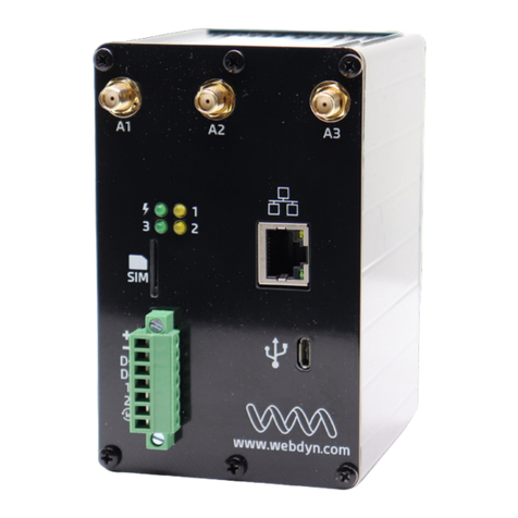
Flexitron WebdynPulse WG0510-A01 User manual

Webdyn
Pulse
The monitoring gateway for your
electric meters
Gateway specification

2
GATEWAY SPECIFICATIO
-
Webdyn
Pulse
WebdynPulse – Gateway specification - Version 2.0
1
Glossary .............................................................................................................. 4
2
About this document............................................................................................ 4
2.1
Scope ........................................................................................................... 4
2.2
Target audience ........................................................................................... 4
2.3
Product versions........................................................................................... 4
2.4
Safety advice................................................................................................ 5
3
Principles of operation......................................................................................... 5
3.1
Overview diagram of a comprehensive monitoring solution ......................... 6
4
Unit characteristics .............................................................................................. 7
4.1
Technical characteristics .............................................................................. 7
4.2
List of available interfaces ............................................................................ 7
4.3
Options and accessories .............................................................................. 8
4.3.1
DIN RAIL POWER SUPPLY ................................................................... 8
4.3.2
GSM/GPRS right-angled stub antenna ................................................... 9
4.3.3
GSM/GPRS externally mounted antenna ............................................. 10
5
Prerequisites ..................................................................................................... 10
5.1
Access to the FTP server ........................................................................... 11
5.2
Access to the NTP server........................................................................... 11
5.3
Connation via GPRS or Ethernet................................................................ 11
5.3.1
Ethernet connection .............................................................................. 12
5.3.2
GPRS connection ................................................................................. 12
5.3.3
Managing the PIN code for the SIM card .............................................. 12
6
Configuring the unit ........................................................................................... 12
6.1
Roles of the WebdynPulse files.................................................................. 13
6.1.1
Configuration files ................................................................................. 13
6.1.2
Definition files........................................................................................ 13
6.2
Initialization ................................................................................................ 13
6.2.1
Configuration via the built-in Web server .............................................. 16
6.2.2
Configuration via SMS .......................................................................... 22
6.3
Setting the unit date and time..................................................................... 23
6.4
Connation modes and periods ................................................................... 23
6.4.1
Manual connection................................................................................ 24
6.4.2
Periodic automatic connection .............................................................. 24
6.4.3
Automatic connection at fixed times...................................................... 25
6.4.4
Automatic connection on data capture.................................................. 26
6.4.5
Keeping the connection open ............................................................... 26
6.4.6
Optimizing the connection..................................................................... 27
6.5
Acquisition period and time slots................................................................ 27
7
Inputs management........................................................................................... 28
7.1
Wiring ......................................................................................................... 28
7.2
Declaring input ports .................................................................................. 29
CONTENT

3
GATEWAY SPECIFICATIO
-
Webdyn
Pulse
WebdynPulse – Gateway specification - Version 2.0
7.3
Input definition files..................................................................................... 30
7.4
Configuration via the local web interface.................................................... 31
7.5
Checking that input ports are operating correctly ....................................... 32
7.6
Input data ................................................................................................... 33
7.6.1
Filename syntax.................................................................................... 33
7.6.2
Format of input data.............................................................................. 33
7.6.3
Example................................................................................................ 34
7.7
Alarms on the digital inputs ........................................................................ 34
7.7.1
Syntax of the alarms file name.............................................................. 35
7.7.2
Format of alarm file ............................................................................... 35
7.7.3
Example of an alarm on a digital input .................................................. 35
8
Upgrading the unit ............................................................................................. 35
8.1
Upgrading via the Web server.................................................................... 36
8.2
Upgrading remotely via the FTP server...................................................... 37
9
Using Web Services .......................................................................................... 37
9.1
Enabling and configuring............................................................................ 37
9.2
Format of HTTP requests........................................................................... 37
9.3
Examples of Web Services requests.......................................................... 40
10
Tools and diagnostics .................................................................................... 40
10.1
Events journal ............................................................................................ 40
10.2
Modem information..................................................................................... 42
10.3
LED indicators............................................................................................ 43
10.4
Installation button ....................................................................................... 44
10.5
Diagnostic SMSs........................................................................................ 44
10.6
Debug traces.............................................................................................. 44
10.7
Factory reset procedure ............................................................................. 46
10.8
Support....................................................................................................... 46

4
GATEWAY SPECIFICATIO
-
Webdyn
Pulse
WebdynPulse – Gateway specification - Version 2.0
1 Glossary
Name Description
AP
Access Point Name
Name of the access point that enables the gateway to connect to the Internet via a
mobile link.
FTP
File Transfer Protocol
Communications protocol used to share data files on a TCP/IP network.
GPRS
General Packet Radio Service
Standard for mobile telephone communications derived from the GSM standard
and enabling higher data transfer rates. Also known as 2.5G.
DL: maximum 86 kbps
UL: maximum 43 kbps
GSM
Global System for Mobile Communications
The switched network for mobile telephones.
HTTP
HyperText Transfer Protocol
Client-server communications protocol developed for the Web.
IP
Internet Protocol
Message protocol controlling the addressing and transmission of TCP packets over
the network.
DI Rail
Standardized 35-mm metal rail used in Europe for rack-mounted industrial control
equipment
TCP
Transmission Control Protocol
A connection-oriented protocol for the Internet, which provides data segmentation
into packets that are transmitted over the network via the IP protocol. This protocol
provides a reliable data transfer service. See also IP.
TCP/IP
Transmission Control Protocol/Internet Protocol
The suite of network protocols that provide interconnection services between
computers with different hardware architectures and operating systems. TCP/IP
includes standards for communication between computers and conventions for
network interconnection and for routing.
2 About this document
The purpose of this guide is to describe the installation and operation of a WebdynPulse gateway.
2.1 Scope
The present technical description is valid for WebdynPulse gateways from hardware version 1
onwards, and from software version V1.01.15 and up.
2.2 Target audience
This guide is intended for users of WebdynPulse gateways.
2.3 Product versions
There are two versions of this unit:
WG0510-A01 Ethernet/GPRS interfaces

5
GATEWAY SPECIFICATIO
-
Webdyn
Pulse
WebdynPulse – Gateway specification - Version 2.0
WG0510-A02 Ethernet/GPRS interfaces - IP55 enclosure - 24V Rail Din power supply
This manual covers only the WG0510-A01 variant. For all specific details concerning the WG0510-A02
variant, please contact WebdynPulse support.
2.4 Safety advice
It is essential to respect all safety recommendations featured in this guide.
Failure to comply with these recommendations may cause damage to equipment and danger to the
health safety of personnel.
Electrical connections
- All wiring must be carried out only by a specialized qualified electrician.
- Prior to installation, all equipment connected to the corresponding
communications bus must be disconnected on both sides (DC and AC).
- Respect all safety recommendations appearing in meter documentation.
The WebdynPulse unit is liable to damage from electrostatic discharge (ES )
Avoid all contact with component connectors and terminals
3 Principles of operation
The WebdynPulse gateway is the communications hub for your electric meters. It continuously
collects all the data from electric meters. It can also detect the switching of circuit breakers or relays.

6
GATEWAY SPECIFICATIO
-
Webdyn
Pulse
WebdynPulse – Gateway specification - Version 2.0
3.1 Overview diagram of a comprehensive monitoring solution
FTP Server
HTTP Server
Web Services
Electric
meters
Local PC (configuration)
Users
Operation
Electric installation
Circuit breakers,
relays …
Internet

7
GATEWAY SPECIFICATIO
-
Webdyn
Pulse
WebdynPulse – Gateway specification - Version 2.0
4 Unit characteristics
4.1 Technical characteristics
Electrical characteristics
Input tension 12 / 24 V
Electricity consumption when idle 2.8 W (1)
Electricity consumption when connected via Ethernet 3.2 W (1)
Maximum peak power during GPRS connection 5 W (1)
GSM/GPRS antenna: Microel EA-247
Frequency 900/1800 MHz
Gain 0 dB
Polarization Vertical
Memory
Storage capacity 100 MB of compressed data
Dimensions
Size 157mm*86mm*58,5mm
Environmental conditions
Operational temperature range -10°C to +55°C
Storage temperature (for a period of less than one month) -20°C to +45°C
Storage temperature (for a period of more than one month) -20°C to +35°C
(1) Measurements carried out on the Unit + DI Rail DR15-24 power supply assembly
4.2 List of available interfaces
ata source
Interface
Characteristics
Pulse counter,
circuit
breakers, relays
Dry contact via 2 wires
Up to 3
Communications channel
Protocol
Ethernet 10/100
Mbps
IP Services
GSM/GPRS Modem
(WGE-G-PV) IP Services
Remote server
Protocol
FTP server with HTTP Web Services
option. FTP and HTTP

8
GATEWAY SPECIFICATIO
-
Webdyn
Pulse
WebdynPulse – Gateway specification - Version 2.0
4.3 Options and accessories
4.3.1 DIN RAIL POWER SUPPLY
Brand: MEA WELL
Reference o.: DR-15-24
This power supply unit is mounted next to the gateway on the standard 35-mm DI RAIL metal rail.
This rail mounting means that no other mounting bracket is required.
•If the DI RAIL unit is used to supply power remotely to analogue modules,
please check the output tension adjustment value.
•In addition, check the power consumption of all remotely powered modules.
Characteristics:
OUTPUT
DC VOLTAGE
24V
RATED CURRE T
0.63A
CURRE T RA GE
0 ~ 0.63A
RATED POWER
15.2W
RIPPLE & OISE (max.) ote.2
150mVp
-
p
VOLTAGE ADJ. RA GE
21.6 ~ 26.4V
VOLTAGE TOLERA CE ote.3
±1.0%
LI E REGULATIO
±1.0%
LOAD REGULATIO
±1.0%
SETUP, RISE TIME
1000ms, 50ms/230VAC
1000ms, 50ms/115VAC at full load
HOLD UP TIME (Typ.)
70ms/230VAC
16ms/115VAC at full load
I PUT
VOLTAGE RA GE
85 ~ 264VAC 120 ~ 370VDC
FREQUE CY RA GE
47 ~ 63Hz
EFFICIE CY (Typ.)
85%
AC CURRE T
(Typ.)
0.88A/115VAC
0.48A/230VAC

9
GATEWAY SPECIFICATIO
-
Webdyn
Pulse
WebdynPulse – Gateway specification - Version 2.0
I RUSH CURRE T (Typ.)
COLD START 35A/115VAC
65A/230VAC
PROTECTIO
OVERLOAD ote.5
105 ~ 160% rated output power
Protection type: Constant current limiting,
recovers automatically after fault condition is
removed
OVER VOLTAGE
27.6 ~ 32.4V
E VIRO ME T
WORKI G TEMP.
-
20°C ~ +60°C (Refer to output load derating
curve)
WORKI G HUMIDITY
20 ~ 90% RH non
-
condensing
STORAGE TEMP., HUMIDITY
-
40°C ~ +85°C, 10 ~ 95% RH
TEMP. COEFFICIE T
±0.03%/ (0 ~ 50)
°C)
VIBRATIO
10 ~ 500Hz, 2G 10min./1cycle, period for 60min.
each along X, Y, Z axes; Mounting: Compliance
to IEC60068-2-6
SAFETY &
EMC
SAFETY STA DARDS
UL60950
-
1, TUV E 60950
-
1 approved, design
refer to E 50178
WITHSTA D VOLTAGE
I/P
-
O/P: 3
KV AC
ISOLATIO RESISTA CE
I/P
-
O/P: 100
megohm / 500
V
DC / 25 / 70% RH
EMI CO DUCTIO &
RADIATIO
Compliance to E 55011, E 55022 (CISPR22),
E 61204-3 Class B
HARMO IC CURRE T
Compliance to E 61000
-
3
-
2,
-
3
EMS IMMU ITY
Compliance to E 61000
-
4
-
2, 3, 4, 5, 6
, 8, 11,
E V50204, E 55024, E 61000-6-2, E 61204-3,
heavy industry level, criteria A
OTHERS
MTBF
1172.3K hr min. MIL
-
HDBK
-
217F (25 )
DIME SIO
25*93*56mm (W*H*D)
4.3.2 GSM/GPRS right-angled stub antenna

10
GATEWAY SPECIFICATIO
-
Webdyn
Pulse
WebdynPulse – Gateway specification - Version 2.0
Characteristics:
Frequency range
900
-
1800
MHz
4.3.3 GSM/GPRS externally mounted antenna
Characteristics:
Cable:
RG
-
58
Cable length:
5,10 or 20 meters available
Frequency ranges
824
-
960
MHz
1710-1990 MHz
Options
Mounting bracket
5 Prerequisites
Configuration of the WebdynPulse is mainly carried out using configuration and definition files, which
are available on a remote FTP server. Consequently, it is vitally important that the WebdynPulse
gateway should have access to an FTP server for downloading and/or uploading its configuration and
definition files, as well as its data, alarm and log files.
In addition, the factory default time and date setting of the gateway is 1
st
January 1970 at 00:00.
Time synchronization is therefore required to enable the data to be correctly time stamped. For this
purpose, the gateway must synchronize itself with an TP ( etwork Time Protocol) server.
For these reasons, it is important to ensure that the prerequisites listed below are correctly entered.

11
GATEWAY SPECIFICATIO
-
Webdyn
Pulse
WebdynPulse – Gateway specification - Version 2.0
5.1 Access to the FTP server
For the configuration of the remote FTP server, it is essential to respect the following configuration:
•Read/Write/Rename access authorized;
•Passive mode enabled;
•Port 21 (by default);
•Short handshake message;
•Login and Password must be less than 30 characters.
As the WebdynPulse gateway does not create any directories, the FTP server must provide the
directories and subdirectories for configuration, definition, data, alarms, commands, logs and
updates. Here is a list of the default directories expected:
•/CONFIG: Contains the configuration files for the gateway.
•/EF: Contains the definition files for the modules and sensors to be controlled:
o/IO: Definition files for analogue and digital input/output, and index entries;
•/BIN: contains the binary files of the gateway for update purposes.
•/ ATA: Directory for upload of data files. This directory contains four subdirectories:
o/IO: Analogue and digital input/output data, and index entries;
•/ALARM: Contains the alarm files.
•/CM : Contains the command and acknowledgement files.
•/LOG: Contains the gateway system log (IDSite_DATE.log) and the debug trace log (disabled
by default, and used only by Webdyn in support mode) IDSite_DATE_debug.log.
It is possible to modify part of the directory tree of the FTP server by modifying the root directories
(“/CO FIG”, “/DEF”, “/DATA”, “/BI ”, “/ALARM”, “/CMD” and “/LOG”) in the configuration of the
WebdynPulse gateway.
5.2 Access to the NTP server
To set its date and time correctly, the WebdynPulse synchronizes itself with an TP server before
each connection to the FTP server. By default, the gateway is configured to synchronize itself with
the TP server “pool.ntp.org”. As this TP server is accessible via the Internet, the gateways must
have valid Internet access (the UDP port 123 must be open for outgoing traffic) for synchronization
to occur.
5.3 Connation via GPRS or Ethernet
Access to the FTP and TP servers may be via an Ethernet connection or a GPRS connection.

12
GATEWAY SPECIFICATIO
-
Webdyn
Pulse
WebdynPulse – Gateway specification - Version 2.0
5.3.1 Ethernet connection
For connection via Ethernet, the following parameters must be supplied:
•IP address of the WebdynPulse on the local network;
•Subnet mask;
•IP address of the router or ADSL modem;
•IP address of the D S server.
5.3.2 GPRS connection
For connection via GPRS, it is essential to procure an activated SIM card with a DATA option, and to
know the values of the following parameters:
•AP (Access Point ame): ame of the GPRS access point. This depends on the operator and
the type of subscription;
•User name and password for connection to the AP .
5.3.3 Managing the PIN code for the SIM card
For connection via GPRS, a card must be inserted into the WebdynPulse gateway. The PI code to
enable access to the card cannot be entered on the gateway. The WebdynPulse unit handles the PI
code for the SIM card automatically. It is for that reason that the SIM card must either be initialized
with no PI code or with a PI code set to 0000 when it is first inserted.
The PI code is managed using the following methods:
- If the PI code is deactivated: GPRS communication is operational for the gateway.
- If the PI code is activated and equal to “0000”: when the gateway is fired up for the first
time, a new PI code is attributed to the SIM card. This PI code is defined on the basis of the ICCID
(Integrated Circuit Card Identification) number of the SIM card installed. It is calculated using a
proprietary Webdyn algorithm. This feature allows fraudulent use of the SIM card to be prevented,
while providing ease of use.
In addition, this same SIM card can be reused in another WebdynPulse, WebdynTIC or WebdynSun
unit without any additional configuration.
- If the card has a PI code that is activated but is neither “0000” nor the code attributed by
the WebdynPulse gateway, communications (including SMSs) will not be operational.
Never insert a SIM card with an activated PIN code that is neither “0000” nor a value
attributed by a WebdynPulse. If you do so, the SIM card will be blocked and the user
will have to unblock it by entering the PUK code manually.
6 Configuring the unit
Configuration of the WebdynPulse gateway should be carried out in several stages. The first stage,
initialization, consists of configuring the WebdynPulse gateway so that it can connect to the FTP
server. The second stage is configuration of the gateway via the remote server. During this stage, it is
possible to modify the whole set of configuration parameters via the files available on the server.

13
GATEWAY SPECIFICATIO
-
Webdyn
Pulse
WebdynPulse – Gateway specification - Version 2.0
6.1 Roles of the WebdynPulse files
Except for the locally accessible parameters enabling connection to the remote FTP server, all
configuration of the unit is performed via the configuration files available on the said server. The files
available on the FTP server must be in A SI format.
Each configuration file is prefixed with a unique identifier named the “prefixID”. This prefix enables
the configuration for each gateway on the server to be customized. Two categories of files are
necessary for configuring the unit: the configuration files and the definition files.
6.1.1 Configuration files
The WebdynPulse has three configuration files:
•prefixID_config.ini: this contains the general parameters of the WebdynPulse.
•prefixID_daq.ini: this contains the parameters required for data acquisition.
•prefixID_var.ini: this contains the information for scheduling connection and data acquisition
times.
These 3 files are contained in the configuration directory on the FTP server. By default, this directory
is “/CO FIG”, but can be modified by means of the variable “FTP_DirConfig” in the file
prefixID_config.ini.
If the gateway does not detect these files on the FTP server, it creates them from its current
configuration. Furthermore, at every connection to the server, the gateway checks the modification
dates and sizes of the files, in order to detect any modification of one of the files. Should a
modification be detected, the file is downloaded by the gateway.
The details of each parameter in the configuration files will be explained as required in the remainder
of this documentation.
6.1.2 Definition files
The role of the definition file is to define the set of data to be collected for a given type of module. It
may be generated automatically by the WebdynPulse unit or created by the IT department
depending on the specific details of the module that is to be managed.
The WebdynPulse therefore possesses as many definition files as there are types of module to be
controlled.
The link between the definition files and the unit is provided via the configuration file
prefixID_daq.ini.
A detailed description of an inverter definition file is provided in the inverter-specific appendices.
6.2 Initialization
Initial configuration of the unit is necessary to enable connection to the remote FTP server. This
configuration can be carried out either via the built-in Web server, or by SMS if this option is
available where connation is done using GPRS.
Local configuration of the WebdynPulse affects only the variables in the configuration file:
prefixID_config.ini.

14
GATEWAY SPECIFICATIO
-
Webdyn
Pulse
WebdynPulse – Gateway specification - Version 2.0
Here is a list of the variables accessible via the local web interface (http) and/or via SMS commands:
Here is a list of the variables accessible via the local web interface (http) and/or via SMS commands:
Variable
efinition
efault value
HTTP
SMS
ID
Gateway identifier
(up to 29 characters)
WDxxxxxx where
xxx… is the last 6
digits of the MAC
address
X
LA _IpAddr
IP address of the gateway
(router) on the LA (local area
network)
Communication via Ethernet
(up to 15 characters)
192.168.1.12
X
LA _SubnetMask
LA subnet mask
Communication via Ethernet
(up to 15 characters)
255.255.255.0
X
LA _Gateway
Address of the gateway
(router) on the LA
Communication via Ethernet
(up to 15 characters)
0.0.0.0
X
LA _D S
Address of the D S server on
the LA
Communication via Ethernet
(up to 15 characters)
0.0.0.0
X
LA _DHCP_Enable
Enable/Disable
DHCP:
For automatic provision of
Ethernet IP addresses.
0=Disabled
1=Enabled
0
X
GPRS_AP
GPRS Access Point ame (AP )
Provided by mobile operator
(up to 29 characters)
m2minternet
X
X
GPRS_Login
GPRS AP identifier
Provided by mobile operator
(up to 29 characters)
sfr
X
X
GPRS_Password
GPRS AP password
Provided by mobile operator
(up to 29 characters)
sfr
X
X
GPRS_Phone umber
Phone number for GPRS
In France: *99***1#
(up to 13 characters)
*99***1#
X
X
FAI_Phone umber
Phone number for PST
empty
X

15
GATEWAY SPECIFICATIO
-
Webdyn
Pulse
WebdynPulse – Gateway specification - Version 2.0
Provided by the Internet
Service Provider (ISP).
(up to 13 characters)
FAI_Login
PST identifier
Provided by the ISP
(up to 29 characters)
empty
X
FAI_Password
PST password
Provided by the ISP
(up to 29 characters)
empty
X
WA _ConnectionInte
rface
Remote server conne
ct
ion
interface selected:
0=Ethernet
1=GPRS modem
1
X
FTP_Server
ame of remote FTP server
(up to 29 characters)
empty
X
X
FTP_Login
Identifier for connation to
remote FTP server
(up to 29 characters)
empty
X
X
FTP_Password
Password for connation to
remote FTP server
(up to 29 characters)
empty
X
X
FTP_Port
Port used for connation to
remote FTP server
21
X
X
FTP_DirConfig
FTP directory name for
gateway configuration files
(up to 29 characters)
/CO FIG
X
FTP_DirDef
FTP directory name for
gateway definition files
(up to 29 characters)
/DEF
X
FTP_DirData
FTP directory name for data
files
(up to 29 characters)
/DATA
X
FTP_DirLog
FTP directory name for log files
(up to 29 characters)
/LOG
X
FTP_DirBin
FTP directory name for
gateway firmware
Used for upgrading gateway
(up to 29 characters)
/BI
X
FTP_DirAlarm
FTP directory name for alarm
files
(up to 29 characters)
/ALARM
X

16
GATEWAY SPECIFICATIO
-
Webdyn
Pulse
WebdynPulse – Gateway specification - Version 2.0
FTP_DirCmd
FTP directory name for
command files
(up to 29 characters)
/CMD
X
FTP_Option
Enable/Disable of two
-
phase
data uploading. (File with
extension “.tmp” uploaded,
then extension “.tmp” deleted
after transfer.
0=Disabled
1=Enabled
0
X
CO FIG_ForceUpload
Allow overwriting
configuration and definition
files on the server if a local
change is performed to a file
parameters concerned:
0 = Off
1 = Enabled
1
X
WebService_Enable
Enable/Disable of web
services:
0= Disabled
1= Enabled
0
X
WebService_Url
Web
Service http:// address
(up to 29 characters)
X
Language
Language chosen for built
-
in
website:
fr = French
en= English
fr
X
These variables can be modified at any time on the remote server.
To ensure consistency between the server and the unit, it is advisable to delete the
unit’s configuration file prefixID_config.ini from the remote server as soon as any local
modification is carried out. This must be done before connecting, so that the gateway
can upload its new prefixID_config.ini configuration file.
6.2.1 Configuration via the built-in Web server
Access to the built-in Web interface on the WebdynPulse gateway is provided via the gateway’s LA
connection. As the gateway does not cross Ethernet signals, when there is a direct connection
between the gateway and the computer, a crossover cable must be used. In addition, both the
computer used and the gateway must belong to the same subnet. If the WebdynPulse gateway has a
static IP address (the default situation), the computer must also be configured to use a compatible
static IP address.
This static address must belong to the same subnet as the WebdynPulse gateway.

17
GATEWAY SPECIFICATIO
-
Webdyn
Pulse
WebdynPulse – Gateway specification - Version 2.0
On delivery, the settings for the WebdynPulse gateway are as follows:
•IP address: 192.168.1.12
•Subnet mask: 255. 255. 255.0
Network administrator
•If your local network is managed by a network administrator, contact him or her
before connecting the WebdynPulse gateway up to your network.
Connecting to the built-in Web interface:
1. Once your computer has been correctly configured:
2. Launch your Web browser (Internet Explorer, Firefox, etc.).
3. Go to the home page of the WebdynPulse gateway using the browser’s address bar to
specify the address http://192.168.1.12.
4. The following window is displayed:
5. Key in the identifier and the password:
On deliver
y, the settings of the WebdynPulse gateway are as follows:
User ame: userhigh
Password: high

18
GATEWAY SPECIFICATIO
-
Webdyn
Pulse
WebdynPulse – Gateway specification - Version 2.0
6. The following home page is displayed:
If the gateway is not yet operating, the following message is displayed:
General configuration:
The onfiguration page allows you to:
•Choose the Web interface language.
•Configure the gateway identifier
•Complete the GPRS / Ethernet connection parameters, and the http/ftp servers.

19
GATEWAY SPECIFICATIO
-
Webdyn
Pulse
WebdynPulse – Gateway specification - Version 2.0
Choosing the language:
Selection the Web interface language from the popup menu.
This field corresponds to the variable “Language” in the configuration file prefixID_config.ini.
Gateway identifier:
This field corresponds to the variable “ID” in the configuration file prefixID_config.ini. The
value of this variable enables identification of the gateway when interacting with the FTP
server. The names of the files available on the server will be prefixed with the value of this
variable, so as to link them to the gateway (i.e. the site) concerned.
There are two ways of configuring the gateway identifier:
•Manually, in the ID field (by default “ID=WDXXXXXX” where XXXXXX is the last six digits of the
MAC address).
•Automatically, by ticking the Automatic mode checkbox and leaving the ID field empty
(“ID= “). For this option, Web Services must be enabled. The gateway will pick up its identifier
just before the initial connection to the FTP server. The ID will be filled in with the value

20
GATEWAY SPECIFICATIO
-
Webdyn
Pulse
WebdynPulse – Gateway specification - Version 2.0
returned by the Web Services server. Should the variable “ID” be deleted once more (“ID= “),
the gateway will request a new identifier on its next connection.
Connection mode:
Choose “Ethernet” or “Modem”, depending on the mode to be used for the connection.
Ethernet:
If the connation mode chosen is “Ethernet”, enter parameters that are valid for your
Ethernet network:
•Address mode: you can obtain the Ethernet parameters automatically if the network
infrastructure and the version of the WebdynPulse can handle this. If this is the case, click
the dynamic radio button and consult the configuration of your DHCP server to find the IP
address attributed to your gateway.
•IP Address: enter the IP address at which the WebdynPulse gateway is accessible.
•Mask: enter the subnet mask for your network. This mask limits the Ethernet network to one
range of defined IP addresses, and separates one network range from another.
•Gateway: enter the address of the gateway to your network. The gateway address is the IP
address IP of the device that establishes the connation to the Internet. In general, the
address entered here is that of the router or ADSL modem.
•DNS: enter the address of the D S server. The D S (Domain ame System) server translates
symbolic Internet addresses (e.g. “www.webdyn.com”) into their corresponding IP
addresses. Here you should enter the address of the D S server you received you’re your
Internet Service Provider (ISP). You can also enter the IP address of your router or ADSL
modem.
If your Ethernet network is managed by a network administrator, contact him or her to
have your WebdynPulse gateway included in the existing Ethernet network.
Modem:
If the connation mode chosen is “Modem”, enter parameters that are valid for your GPRS
subscription:
•all number: enter the phone number for the GPRS connection. The default number
is “*99***1#”, which is valid in most cases. This number is not the phone number of
the SIM card fitted to the unit.
•APN: enter the Access Point ame (AP ) supplied by your mobile operator.
•Login: enter the user ID for the AP supplied by your mobile operator.
•Password: enter the password for the AP supplied by your mobile operator.
Consult your mobile operator to obtain the information pertaining to your SIM card
(AP , user ID and password).
This manual suits for next models
1
Table of contents
Other Flexitron Gateway manuals
Popular Gateway manuals by other brands
WELLTECH
WELLTECH 2540 FXO user guide
Dinstar
Dinstar UC100 user manual
Lucent Technologies
Lucent Technologies PacketStar PSAX user guide
IFM Electronic
IFM Electronic AC1376 installation instructions

ADTRAN
ADTRAN 7310-8 Getting started guide

Ferrari electronic
Ferrari electronic OfficeMaster Gate user manual
