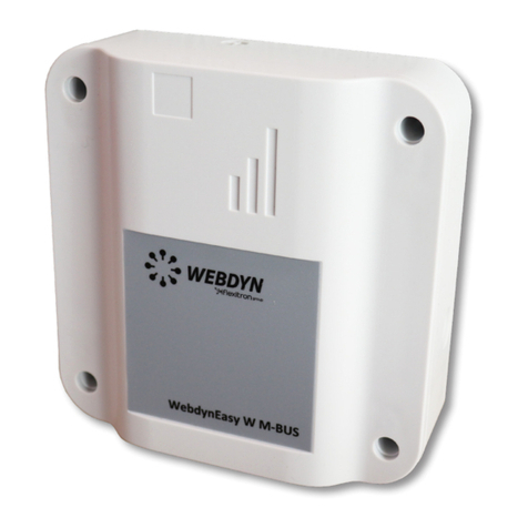
Flexitron Webdyn WebdynEasy W M-Bus User manual

WebdynEasy W M-Bus 868MHz
User Manual
www.webdyn.com

contact@webdyn.com | webdyn.com
V1.0 subject to changes | Webdyn © by Flexitron Group
contact@webdyn.com | webdyn.com
V1.0 subject to changes | Webdyn © by Flexitron Group
2
3
2.4.3 Cellular Network ........................................................................................................ 22
2.4.4 Indicators & Buttons .................................................................................................. 23
2.4.5 USB Interface.............................................................................................................. 25
2.4.6 Bluetooth Interface (BLE)........................................................................................... 26
3. Product Operation................................................................................................................................. 27
3.1 Starting the Product................................................................................................................. 27
3.1.1 Operating Mode .......................................................................................................... 27
3.1.2 Application Operation................................................................................................. 32
4. Conguration......................................................................................................................................... 33
4.1 Local Conguration .................................................................................................................. 33
4.1.1 USB .............................................................................................................................. 33
4.1.2 Bluetooth (BLE)........................................................................................................... 33
4.2 Conguration File ..................................................................................................................... 35
4.2.1 System......................................................................................................................... 35
4.2.2 W M-Bus radio ............................................................................................................ 39
4.2.3 Hub Connectivity......................................................................................................... 42
4.2.4 Alarms ......................................................................................................................... 47
4.2.5 Schedule and Monitoring........................................................................................... 48
5. Operation............................................................................................................................................... 53
5.1 The Remote Server................................................................................................................... 53
5.1.1 The FTP Server............................................................................................................ 53
5.2 The Conguration..................................................................................................................... 56
5.3 The Data ................................................................................................................................... 58
5.4 Alarms....................................................................................................................................... 60
5.5 ACK Acknowledgements.......................................................................................................... 61
5.6 Commands ............................................................................................................................... 63
5.6.1 “Request” Command.................................................................................................. 64
5.6.2 “Factory” Command................................................................................................... 65
5.6.3 “Update” Command ................................................................................................... 65
5.6.4 “Status” Command .................................................................................................... 65
5.6.5 “Diag” Command........................................................................................................ 66
5.6.6 “CongGet” Command............................................................................................... 66
Index
1. Glossary................................................................................................................................................. 5
2. About this Document............................................................................................................................ 7
2.1 Scope ........................................................................................................................................ 7
2.2 Target Audience........................................................................................................................ 7
2.3 Product Versions ...................................................................................................................... 7
User Manual ..................................................................................................................... 8
1. Presentation.......................................................................................................................................... 8
1.1 General Description ................................................................................................................. 8
1.2 Operating Principle................................................................................................................... 8
1.3 Interfaces.................................................................................................................................. 9
1.4 Supported Equipment.............................................................................................................. 10
1.5 Product and Accessory References ........................................................................................ 10
1.6 Technical Specications .......................................................................................................... 10
1.6.1 General Specications ............................................................................................... 10
1.6.2 Technical Specications............................................................................................. 11
1.6.3 Software Specications ............................................................................................. 14
1.6.4 Battery Life.................................................................................................................. 14
1.7 Safety Instructions ................................................................................................................... 15
1.8 Regulations............................................................................................................................... 16
2. Installation ............................................................................................................................................ 17
2.1 Prerequisite ............................................................................................................................. 17
2.2 Unpacking................................................................................................................................. 17
2.2.1 Contents...................................................................................................................... 17
2.2.2 Identication ............................................................................................................... 17
2.3 Assembly................................................................................................................................... 19
2.3.1 Opening/Closing the Box ........................................................................................... 19
2.3.2 Wall Mounting............................................................................................................. 19
2.4 Interface Description ............................................................................................................... 19
2.4.1 Product Power Supply................................................................................................. 19
2.4.2 Radio ........................................................................................................................... 21

contact@webdyn.com | webdyn.com
V1.0 subject to changes | Webdyn © by Flexitron Group
contact@webdyn.com | webdyn.com
V1.0 subject to changes | Webdyn © by Flexitron Group
4
5
5.6.7 “whiteListErase” Command....................................................................................... 67
5.6.8 “operatorInit” Command............................................................................................ 67
5.6.9 “logGet” Command .................................................................................................... 68
5.6.10 “logClean” Command............................................................................................... 68
5.6.11 “supervisionClean” Command ................................................................................ 69
5.7 Supervision............................................................................................................................... 69
5.8 The Log ..................................................................................................................................... 74
6. Update ................................................................................................................................................... 77
6.1 Local.......................................................................................................................................... 78
6.2 Remote...................................................................................................................................... 78
7. Tools & Diagnostics............................................................................................................................... 79
8. FAQ......................................................................................................................................................... 79
9. Appendix................................................................................................................................................ 80
9.1 Conguration - Variable list...................................................................................................... 80
Ofces & Support Contact............................................................................................... 83
1. Glossary
NAME DESCRIPTION
APN Access Point Name: the name of the access point the gateway uses to connect to
the Internet via a mobile connection.
AES Advanced Encryption Standard: synthetic encryption algorithm.
BLE Bluetooth Low Energy: wireless transmission technique in the form of a Bluetooth-
based open standard, characteristically having much lower power consumption.
Base64 Encoded data using an alphabet with 64 characters.
BSON Binary JSON: binary version of JSON: encoding used to reduce the size of
transmitted data to save stand-alone system batteries.
FTP File Transfer Protocol: communication protocol used to exchange les over a TCP/
IP network.
FTPS File Transfer Protocol Secure: communication protocol intended for the computer
exchange of les on a TCP / IP network, variant of FTP, secured with SSL or TLS
protocols. It allows visitors to verify the identity of the server they are accessing
using an authentication certicate. It also makes it possible to encrypt the
communication.
2G Second generation: second generation digital standard (2G) for mobile telephony
including GSM, GPRS and EDGE.
HTTP HyperText Transfer Protocol: client-server communication protocol developed for
the Web.
IP Internet Protocol: message protocol in charge of addressing and sending TCP
packets over the network.
JSON JavaScript Object Notation: JSON is an easily interpretable data exchange format.
LTE-M/
CAT-M1
Long Term Evolution – Machine: 4G mobile network specic to connected objects,
i.e. low consumption and long range.
NTP Network Time Protocol: an NTP server makes it possible to time synchronise
equipment.
IS Information System: server with which the hub exchanges (conguration, data,
alarms, etc.).

contact@webdyn.com | webdyn.com
V1.0 subject to changes | Webdyn © by Flexitron Group
contact@webdyn.com | webdyn.com
V1.0 subject to changes | Webdyn © by Flexitron Group
6
7
TCP Transmission Control Protocol: an Internet-based connection-oriented protocol
that provides data packet segmenting services that the IP protocol sends over the
network. This protocol provides a reliable data transfer service. See also IP.
TCP/IP Transmission Control Protocol/Internet Protocol: a set of network protocols
that provide interconnection services between computers of different
hardware architectures and operating systems. TCP/IP includes standards for
communication between computers and conventions for network interconnection
and routing.
W M-BUS Wireless M-Bus: evolution of the European Mbus standard in a radio frequency
adaptation. This connectivity is specic to metering applications such as: water,
gas and electricity meters.
2. About this Document
This guide describes all features of the WebdynEasy W M-Bus product.
Its purpose is to help operators install and congure their WebdynEasy W M-Bus and to allow operating
entities to include the collected data in their IS.
This manual is split into six separate sections:
• Section 1: General presentation
• Section 2: Installation
• Section 3: Conguration
• Section 4: Operation
• Section 5: Tools & diagnostics
• Section 6: FAQ
2.1 Scope
This technical description is valid for WebdynEasy W M-Bus hubs from hardware version V1 and software
version V1.0 onwards.
2.2 Target Audience
This guide is for on-site installers who will cable and congure the installations, for those in charge of
local or remote maintenance of the installations, and for developers of portals to use the sent data.
2.3 Product Versions
VERSION CONTENT
V1.0 Creation.
V1.1 Modication of the functioning of the product regards the magnet and the
number of bips. Adding of a scheme concerning le management.
V1.2 Addition and Modication on the supervision part. Adding autonomy.
V1.3 Additions in the glossary, modication of the command le.
V1.4 Additions on Field L for B format frames.
V1.5 Details on the data parameter F and on the diagnostic mode, adjustment of
the/scheduleRadio/data range.

contact@webdyn.com | webdyn.com
V1.0 subject to changes | Webdyn © by Flexitron Group
contact@webdyn.com | webdyn.com
V1.0 subject to changes | Webdyn © by Flexitron Group
8
9
User Manual
1. Presentation
1.1 General Description
The purpose of the WebdynEasy W M-Bus hub is to collect data from Wireless M-Bus sensors such as
meters (water, gas and electricity) and sensors (temperature, humidity, etc...). This technology is energy-
efcient, the hub battery service life can exceed 10 years.
Data collection is by radio on the 868MHz frequency. This frequency is free of charge and its use is
harmonised in many EU countries.
The collected information (data, parameters, alarms, ...) is formatted to BSON format before being sent
to an information system (IS) by modem.
1.2 Operating Principle
WebdynEasy W M-Bus allows you to build your private network and is part of a package. WM-Bus
communication is point-to-point in a non-operated way. The meters or sensors regularly send data
frames, which are received and the raw data (encrypted or transparent) contained in these frames are
stored by the WM-Bus hub. WebdynEasy W M-Bus will regularly send a le in BSON format containing the
whole raw data of the different sensors to a server via FTP using its 2G/LTE-M or modem. It is possible to
secure the exchanged les between the WebdynEasy W M-Bus and the FTP server by activating the AES
encryption (see chapter 4.2.1.2 : “security”).
WebdynEasy W M-Bus can be congured by connecting it to a computer via USB or by BLE using a
smartphone app.
NB, LTE-M, 2G
cellular network
Other W M-Bus
equipment
WebdynEasy W M-Bus
868MHz
Water and
electricity meters
Server User
Wireless M-Bus
888888
1.3 Interfaces
1. HALL effect sensor
2. Buzzer
3. Mini-USB connector
4. Indicators:
• LED 1: reserved
• LED 2: reserved
• LED 5: Modem status
5. 868MHz radio SMA antenna
6. Box output for the 868MHz radio external antenna (optional)
7. Battery Pack
8. Battery pack connector
9. Aerator
10. Box output for external power supply (optional)
11. Terminal block for external 12 V power supply
12. Box output for the 2G/LTE-M modem external antenna (optional)
13. 2G/LTE-M Modem SMA Antenna
14. Reset button
15. SIM card holder

contact@webdyn.com | webdyn.com
V1.0 subject to changes | Webdyn © by Flexitron Group
contact@webdyn.com | webdyn.com
V1.0 subject to changes | Webdyn © by Flexitron Group
10
11
1.4 Supported Equipment
The hub supports all equipment compliant with the 868MHz Wireless M-Bus standard and using one of
the following modes: T1, S1 and T1+C1.
1.5 Product and Accessory References
Product:
REFERENCES DESCRIPTIONS
WG0612-A12 WebdynEasy W M-Bus
Accessories:
REFERENCES DESCRIPTIONS
AC0803-01 Battery pack 7.2V / 14Ah
Webdyn proposes factory preconguration services for your WebdynEasy W M-Bus. Please contact our
sales department for further information.
1.6 Technical Specications
1.6.1 General Specications
REFERENCES DESCRIPTIONS
Power supply +12V 1A
Battery 7.2V 14Ah lithium battery pack (non-rechargeable) - in optimal conguration,
the battery can last up to 10 years
Consumption P: 2 W
Pmax: 5 W
Dimensions 160 x 150 x 55 mm
Box ASA
Protected against dust and bad weather
Weight 0.600 kg with battery pack
0.450 kg without battery pack
Operating
temperature -20ºC/+55ºC
Storage
temperature
-20ºC/+70ºC (without battery)
-20ºC/+25ºC (with battery)
Humidity 25% - 75%
Pollution rating 2
Certication RED
ROHS
REACH
Regulation
CE marking created in the framework of European technical
harmonisation legislation. It is mandatory for all products covered by one or
more European regulatory texts (directives or regulations).
Symbol indicating that the waste must be collected via a specic
channel and must not be disposed of as household waste.
Symbol indicating that the product must be recycled.
1.6.2 Technical Specications
REFERENCES DESCRIPTIONS
Memory capacity for data • Flash: 1.5MB (circular operation)
• 2000 frames per listening window
Radio interference Frequency: 868 MHz
Antenna: Internal SMA (external as an option)

contact@webdyn.com | webdyn.com
V1.0 subject to changes | Webdyn © by Flexitron Group
contact@webdyn.com | webdyn.com
V1.0 subject to changes | Webdyn © by Flexitron Group
12
13
Cellular Interface Modem GSM/GPRS/EDGE/LTE-M modem
• 2G (GSM, GPRS): 850/900/1800/1900 MHz
• LTE-M1: B1/B2/B3/B4/B5/B8/B12/B13/B18/B19/B20/
B25/B26/B27/B28/B66/B85
Antenna: Internal SMA (external as an option)
BLE interface 160 x 150 x 55 mm
SIM format ASA
Protected against dust and bad weather
Webdyn does not supply any SIM cards. Please contact an M2M operator that supports the 2G
and LTE-M network.
Connectivity data:
RF BAND EMISSION FREQUENCIES MAX. POWER
2G GSM 900 880 MHz – 915 MHz
33 dBm (class 4)
2G GSM 850 824 MHz – 849 MHz
2G DCS 1800 1710 MHz – 1785 MHz
30 dBm (class 1)
2G PCS 1900 1850 MHz – 1910 MHz
LTE-M - Band 1 1920 MHz – 1980 MHz
21 dBm (class 5)
LTE-M - Band 2 1850 MHz – 1910 MHz
LTE-M - Band 3 1710 MHz – 1785 MHz
LTE-M - Band 4 1710 MHz – 1755 MHz
LTE-M - Band 5 824 MHz – 849 MHz
LTE-M - Band 8 880 MHz – 915 MHz
LTE-M - Band 12 699 MHz – 716 MHz
LTE-M - Band 13 777 MHz – 787 MHz
LTE-M - Band 18 815 MHz – 830 MHz
LTE-M - Band 19 830 MHz – 845 MHz
LTE-M - Band 20 832 MHz – 862 MHz
LTE-M - Band 25 1850 MHz – 1915 MHz
LTE-M - Band 26 814 MHz -849 MHz
LTE-M - Band 27 807 MHz – 824 MHz
LTE-M - Band 28 703 MHz – 748 MHz
LTE-M - Band 66 1710 MHz – 1780 MHz
LTE-M - Band 85 698 MHz – 716 MHz
BLE 2402 MHz – 2480 MHz 0 dBm

contact@webdyn.com | webdyn.com
V1.0 subject to changes | Webdyn © by Flexitron Group
contact@webdyn.com | webdyn.com
V1.0 subject to changes | Webdyn © by Flexitron Group
14
15
1.6.3 Software Specications
SPECIFICATIONS DESCRIPTIONS
Wireless M-Bus T1, S1 and T1+C1 mode
BSON Specication 1.1
1.6.4 Battery Life
Battery life may vary depending on product use and environmental conditions.
The tables below are estimates taking into account:
• Standard environmental conditions.
• 1 radio listening window per day.
• 20KB of data recorded per listening window (ie 300 frames of 64 bytes or 500 frames of 40
bytes).
With LTE-M:
LENGTH OF LISTENING
WINDOW IN MINUTES 2 UPLOADS/DAY 1 UPLOAD/DAY 1 UPLOAD/WEEK
2 > 15 years > 15 years > 15 years
4 13 years > 15 years > 15 years
5 12 years 14 years > 15 years
6 11 years 13 years 13 years
8 9 years 10 years 11 years
10 8 years 9 years 9 years
12 7 years 7 years 8 years
15 6 years 6 years 6 years
20 5 years 5 years 5 years
30 3 years 3 years 3 years
With 2G:
LENGTH OF LISTENING
WINDOW IN MINUTES 2 UPLOADS/DAY 1 UPLOAD/DAY 1 UPLOAD/WEEK
2 > 15 years > 15 years > 15 years
4 12 years > 15 years > 15 years
5 11 years 13 years 14 years
6 10 years 12 years 12 years
8 8 years 10 years 10 years
10 7 years 8 years 8 years
12 6 years 7 years 8 years
15 5 years 6 years 6 years
20 4 years 5 years 5 years
30 3 years 3 years 3 years
1.7 Safety Instructions
Follow all the safety instructions in this guide.
Failure to follow these instructions can damage equipment and endanger people.
Electric connection:
• All wiring work must be carried out by a specialised qualied electrician.
• Please follow all the safety instructions featured in the equipment documentation.
The WebdynEasy W M-Bus product can be damaged by electrostatic discharges (ESD). When the
equipment is open, do not carry out any operations other than those described in this manual. Avoid any
contact with the components.
Class 3 equipment: the device operates on safety extra-low voltage (SELV) (50V maximum). The
voltage reduction must be obtained using a safety transformer providing safe galvanic isolation between
primary and secondary.

contact@webdyn.com | webdyn.com
V1.0 subject to changes | Webdyn © by Flexitron Group
contact@webdyn.com | webdyn.com
V1.0 subject to changes | Webdyn © by Flexitron Group
16
17
Do not install the equipment near a heat source or at a height greater than 2m.
To clean the product, only use a slightly damp cloth to gently clean and wipe the surfaces. Never
use aggressive chemical agents or solvents that could alter the plastic material or corrode the metal
parts.
Never insert a battery other than the one recommended by Webdyn. Never recharge the battery.
To optimise radio and cellular modem reception sensitivity, it is imperative to leave 20 cm free
space around the antennas.
1.8 Regulations
The product complies with the European directives according to the EU Declaration of Conformity available
from Webdyn or on website: www.webdyn.com
Recycling:
The European directives enacted into national law covering battery waste and electric and
electronic equipment provide the framework for the actions needed to limit the negative impact of the
product’s end of life.
These products are collected separately. Use an authorised battery collection and processing centre or
contact Webdyn.
2. Installation
2.1 Prerequisite
Since the role of the hub is to send the data it collects to an IS, the installation requires sufcient
knowledge of the hub, but also of the information system to which it sends its data.
The following is required to ensure proper installation:
• To have this user manual to hand.
• To have a screwdriver suitable for the types of connectors and screws available on the
WebdynEasy W M-Bus hub.
• To have knowledge of the parameters to connect to the IS information system.
• To have a SIM card with an activated data subscription and knowledge of the provider’s APN.
• To have a magnet.
It is also strongly recommended to have the elements described below for any intervention on site and
to install the product.
• Use a remote antenna if radio or cellular modem reception is deteriorated.
• Have an Android smartphone with the WebdynEasy W M-Bus app installed to facilitate product
conguration.
• Have a PC for product conguration or update via USB.
2.2 Unpacking
2.2.1 Contents
The WebdynEasy W M-Bus hub comes standard with:
• A curved SMA antenna for the modem (internal).
• A curved SMA antenna for the radio (internal).
• A battery pack.
2.2.2 Identication
The commercial reference differs depending on whether or not the hub includes a customer conguration.
The commercial reference is composed as follows:
• Without conguration: the commercial reference is WG0612-A12.
• With conguration: the commercial reference is WG0612-A12 to which the customer identier
is added. For example, the following reference can be obtained: WG0612-A12-WG.
A unique identier called UID is assigned to each WebdynEasy W M-Bus. It is used to congure the
product and recognise it when you have several WebdynEasy W M-Bus products.

contact@webdyn.com | webdyn.com
V1.0 subject to changes | Webdyn © by Flexitron Group
contact@webdyn.com | webdyn.com
V1.0 subject to changes | Webdyn © by Flexitron Group
18
19
The QR Code is used by the mobile app for synchronisation with the hub.
Each product is labelled with the following information:
This label is accessible on the underside of the product:
2.3 Assembly
2.3.1 Opening/Closing the Box
Follow these steps to open the hub box:
If the box is wall-mounted:
• Open the 2 doors on the front panel.
• Unscrew the 4 wall mounting screws in the recesses under the doors.
Then follow these steps:
• Unscrew the 4 screws behind the box.
• Remove the cover.
Follow these steps to close the hub box:
• Place the cover on the box base, make sure the seal is properly tted.
• Screw in the 4 screws on the back of the box.
2.3.2 Wall Mounting
The WebdynEasy W M-Bus can be wall-mounted. Before wall-mounting, rst close the box (see section
2.3.1: “Opening/closing the box”).
Screws and anchors are not included in the kit. You must choose the correct type of screw for the
type of wall you are xing the hub to (screw with a diameter of 4mm and a length of 25mm minimum).
Follow the steps below to x the hub to a wall:
• Open the 2 doors on the front panel.
• Screw the 4 wall mounting screws into the recesses under the doors.
• Close both doors on the front.
2.4 Interface Description
2.4.1 Product Power Supply
External Power Supply
The WebdynEasy W M-Bus hub can be powered using 12V DC with or without a battery pack connected.
Power is supplied from terminal block J8 on the left side of the battery pack.

contact@webdyn.com | webdyn.com
V1.0 subject to changes | Webdyn © by Flexitron Group
contact@webdyn.com | webdyn.com
V1.0 subject to changes | Webdyn © by Flexitron Group
20
21
End users must use a CE certied power supply of less than 15 watts. The distance between the
power supply and the product must not exceed 3 metres. End users must make sure their installation
meets applicable EMC standards.
Make sure the power supply wires are connected to the proper terminals.
Product power consumption varies depending on its conguration. Make sure the power supply used can
provide a minimum power of 10 watts.
Battery Pack
The WebdynEasy W M-Bus hub has a Lithium battery that can keep the product running for 10 years. The
hub includes a gauge that provides a battery consumption estimate as soon as it is installed.
The battery pack is xed to the board in a reserved slot using a cable clamp and plugs into the connector
marked “Batt” on the board.
Never install battery packs that are not new. Once a battery pack is installed, never disconnect it
except to replace it.
CAUTION, THERE IS A RISK OF EXPLOSION IF THE BATTERY PACK IS REPLACED BY A BATTERY
PACK OTHER THAT RECOMMENDED BY WEBDYN. DISPOSE OF USED BATTERY PACKS ACCORDING TO
THE INSTRUCTIONS.
2.4.2 Radio
The hub has an 868MHz radio to receive Wireless M-Bus frames from the surrounding sensors.
Antenna
The hub has a female SMA connector labelled “RF” on the board to connect a radio antenna. The product
is delivered with an internal antenna. An external antenna can be connected to the product. To do this,
unscrew the cap on the box and t a M16*1.5 cable gland (not included).
To optimise the radio range, it is important to install the radio antenna as high as possible and to place
it carefully, avoiding obstacles as far as possible. As a priority, move it away from any metal (cupboard,
beams...) or concrete (reinforced concrete, walls...) obstacles as they greatly attenuate radio waves.
End users must make sure their installation using remote antennas meets applicable EMC
standards.

contact@webdyn.com | webdyn.com
V1.0 subject to changes | Webdyn © by Flexitron Group
contact@webdyn.com | webdyn.com
V1.0 subject to changes | Webdyn © by Flexitron Group
22
23
2.4.3 Cellular Network
The WebdynEasy W M-Bus hub includes a 2G and LTE-M network compatible modem.
Antenna
The hub has a female SMA connector labelled “4G” on the board to connect a modem antenna. The
product is delivered with an internal antenna. An external antenna can be connected to the product. To
do this, unscrew the cap on the box and t a M16*1.5 cable gland (not included).
If the WebdynEasy W M-Bus hub were to be installed in a metal box or in a location that does not
have proper signal reception, the use of a remote antenna is strongly recommended. Be careful to use
an antenna compatible with the connector and frequencies used.
End users must make sure their installation using remote antennas meets applicable EMC
standards.
SIM Card
To use the LTE-M or 2G modem connection to allow the hub to communicate with the remote server, the
box must be opened(see section2.3.1: “Opening/closing the box”) and a mini SIM card inserted into the
SIM card housing inside the hub.
The hub is compatible with all market operators as well as with all mini SIM 2FF 25 x 15mm format SIM
cards.
To check that the WebdynEasy W M-Bus is operating properly, insert a SIM card with the following
specications:
• 2G or LTE-M communication included.
To insert the SIM card into the product, slide the holder ap to the right (in the OPEN direction). Slide the
SIM card into the ap. Then close the ap by sliding it to the left (in the LOCK direction)
Webdyn does not supply any SIM cards. Please contact an M2M operator that supports the 2G
and LTE-M network.
Please contact your SIM card provider to nd out what information to enter to conguration the
modem.
If the SIM card has an activated PIN code and it is incorrect the rst time the hub isstarted , it will
be blocked after 3 attempts. It can be unlocked using a mobile phone using the PUK code provided by
the operator.
2.4.4 Indicators & Buttons
The hub is equipped with:
• 1 Hall Effect sensor.
• 1 push button.
• 1 modem indicator.

contact@webdyn.com | webdyn.com
V1.0 subject to changes | Webdyn © by Flexitron Group
contact@webdyn.com | webdyn.com
V1.0 subject to changes | Webdyn © by Flexitron Group
24
25
Hall Effect Sensor
The WebdynEasy W M-Bus hub is equipped with a Hall effect sensor that activates when a magnet is
passed over the top of the box.
The Hall effect sensor is used for various actions such as:
• Requesting the current operating mode and activating the interfaces for local conguration.
• Changing the operating mode.
• Re-applying factory settings (combined with the RESET button).
RESET Button
The RESET button has two functions:
• Restarting the product: a short press on the button
• Re-applying factory settings by following this procedure:
• Place the magnet on the top of the box opposite the Hall effect sensor and keep it in
place.
• Briey press the RESET button.
• A long beep (1 second) is issued, informing that the factory settings have been re-applied.
• Remove the magnet.
Modem LED
The Modem led lights when the modem is activated to upload les to the remote server.
2.4.5 USB Interface
The hub USB interface can be used for:
• Conguration.
• Commands.
• Product updates.
For proper operation, it is essential to strictly follow the steps below:
• Switch the WebdynEasy W M-Bus to RUN mode.
• Connect the hub to a computer using a USB cord (A male - mini B male type).
• A new drive called “WebdynEasy W M-Bus” will appear on the computer (like a thumb drive).
• Open this drive.
• Copy the conguration, command or update le to the hard drive.
• Eject the removable drive and wait for conrmation from the system.
• Press the RESET button.
• The product restarts.
• The following steps are optional and are based on the commands issued.
• A new drive called “WebdynEasy W M-Bus” will appear on the computer (like a thumb drive).
• Open this drive.
• Open the ACK le and check the result of the command OR retrieve the les requested by the
command.

contact@webdyn.com | webdyn.com
V1.0 subject to changes | Webdyn © by Flexitron Group
contact@webdyn.com | webdyn.com
V1.0 subject to changes | Webdyn © by Flexitron Group
26
27
• Eject the removable drive and wait for conrmation from the system before disconnecting the
USB cord.
Never disconnect the USB cord or restart the board before having the system eject the removable
drive. You could damage the le system and corrupt the loaded les.
If the removable drive is inaccessible, you must format it as FAT32.
2.4.6 Bluetooth Interface (BLE)
The hub Bluetooth interface (BLE) is used by the “WebdynEasy W M-Bus” mobile app to:
• Congure.
• Run a diagnostics command concerning its operating.
The “WebdynEasy W M-Bus” app is available for Android and downloadable from Google Play.
3. Product Operation
3.1 Starting the Product
By default, the WebdynEasy W M-Bus hub is shipped in either:
• STORAGE mode: if the product is delivered with a customer conguration.
• FACTORY SETTINGS mode: if the product is delivered without a conguration.
These are low-power modes for products to be stored for long periods of time limiting battery consumption.
To nd out whether the WebdynEasy W M-Bus has a customer conguration, check the product’s
commercial reference. (see section 2.2.2: Identication)
To change mode and wake up the product, slowly pass a magnet over the top of the box in the indicated
location (see location above) until the hub emits the rst beep. The number of beeps issued by the
WebdynEasy W M-Bus indicates the current mode.
3.1.1 Operating Mode
The module has 3 operating modes:
• FACTORY SETTINGS (no conguration).
• STORAGE (conguration).
• RUN
Mode changes are always initiated by the installer.

contact@webdyn.com | webdyn.com
V1.0 subject to changes | Webdyn © by Flexitron Group
contact@webdyn.com | webdyn.com
V1.0 subject to changes | Webdyn © by Flexitron Group
28
29
The state machine below shows the 3 modes, the mode change conditions, and the beeps for each
mode.
An action on the Hall Effect sensor is taken into account as soon as a magnet passes over it. For example,
if a magnet passage is passed over the Hall Effect sensor, one or more beeps will sound informing of the
current hub mode. When a magnet is passed a second time within 10 seconds of the rst pass, the hub
will switch to RUN mode.
Each mode (STORAGE, FACTORY SETTINGS and RUN) is associated with a number of beeps indicating
the equipment status.
The mode can be changed by specifying it when sending a conguration to the hub.
From an installer’s point of view:
• Passing a magnet once gives the current mode:
• 1 short beep: the product is in FACTORY SETTINGS mode (no customer conguration).
• 1 long beep: an action is underway, please wait for the action to end to ask for the function
mode.
• 2 short beeps: the product is in STORAGE mode (customer conguration).
• 3 short beeps: the product is in RUNmode and the last connection with the server was
successful.
• 3 long beeps: the product is in RUNmode and the last connection with the server has
failed.
• Passing a magnet twice in less than 10 seconds changes the current mode:
• In STORAGE mode.
• 3 long beeps + 1 long beep: the product executes the action associated with the
magnet (activation of BLE, Diagnosis command, request command) and switches
to RUNmode.
• In RUNmode.
• 1 long beep: the product executes the action associated with the magnet (activation
of BLE, Diagnosis command, request command) and stays in RUNmode.
• Presence of a magnet + pressing the RESET button switches back to “factory settings”:
• 1 long beep: the product starts its “factory settings” process.
FACTORY SETTINGS Mode
The product is delivered in FACTORY SETTINGS mode if it has no conguration. The hub is then on
standby and its consumption is minimal. When a magnet is passed, a short beep will sound to indicate
that the magnet has been detected, indicate the mode and activate the conguration.
Exiting FACTORY SETTINGS mode is only possible by conguring the product.
The hub can be congured using:
• USB: Connecting the USB cord automatically wakes up the product.
• Bluetooth (BLE): BLE is activated when the magnet is passed over the product.
To optimise battery consumption, the interfaces will automatically shut down after 4 minutes without any
activity. To reactivate the interfaces, a new conguration phase will need to be launched.
The required mode can be set when conguring the product.
To nd out whether the WebdynEasy W M-Bus has a customer conguration, check the product’s
commercial reference. (see section 2.2.2: Identication).
STORAGE Mode
The product is delivered in STORAGE mode if it has a factory pre-conguration. The hub is then on standby
and its consumption is minimal. When a magnet is passed, a short beep will sound to indicate that the
magnet has been detected and indicate the mode.
Exit from STORAGE mode requires passing a magnet over the hub twice in less than 10 seconds and
switches the hub to RUN mode.
To nd out whether the WebdynEasy W M-Bus has a customer conguration, check the product’s
commercial reference. (see section 2.2.2: Identication)

contact@webdyn.com | webdyn.com
V1.0 subject to changes | Webdyn © by Flexitron Group
contact@webdyn.com | webdyn.com
V1.0 subject to changes | Webdyn © by Flexitron Group
30
31
RUNmode
RUN mode runs the product in its end use mode. It is used to regularly run the collection of WM-BUS
data from the sensors and to connect the modem to upload the data to the server. When the product is
inactive, it switches to standby mode to optimise its battery. When a magnet is passed over it, three short
beeps will sound to indicate the magnet has been detected, indicate its mode and informs about the last
connection with the server:
• 3 short beeps: the last connection with the server has been successful.
• 3 long beeps: the last connection with the server has failed.
A second passing of the magnet within 10 seconds permits the execution of an action (activation of BLE,
diagnosis command or request command) and returns to RUNmode.
The hub can be congured using:
• USB: Connecting the USB cord automatically wakes up the product.
• Bluetooth (BLE): BLE is activated when the magnet is passed over the product for the second
time and if the precongured action is “Bluetooth BLE+Modem” (see chapter 4.2.1.1: “Local”).
To optimise battery consumption, the interfaces will automatically shut down after 4 minutes without any
activity. A new conguration phase will need to be launched to reactivate it if necessary.
The required mode can be set when conguring the product. When the hub applies the conguration,
users will be notied of the current mode by the buzzer.
In STORAGE or RUNmode, an action is started upon the second passage of the magnet over the product
before it starts the RUNmode (see chapter 4.2.1.1. “Local”).
There are 3 possibilities:
• Activation of Bluetooth BLE + Modem: The product waits for a conguration or an update via
Bluetooth or Modem within 4 minutes before starting the RUNmode and deactivating the
Bluetooth and Modem.
• Diagnosis Command: Allows the recovery of WM-Bus data of the sensors over a congured
period of time (see the radio paremeters “cong>radio>duration”) and starts a connection
via Modem to deposit them onto the server. At the end of the diagnosis, the concentrator will
inform regarding the result by:
• 3 short beeps if everything went well.
• 3 long beeps if an error occurred.
• Request command: Allows the connection via Modem to deposit or recover a le (conguration,
data, supervision,…) onto the FTP server. At the end of the connection, the concentrator will
inform of the result by:
• 3 long beeps if the connection with the server has failed.
• 3 short beeps if the connection with the server was successful.
RESET
The WebdynEasy W M-Bus has 2 RESET functions that can be triggered using the RESET button (see
section 2.4.4.2.: “RESET button).
• RESTART of the product.
• Hard RESET of the product conguration.
Hall Effect Sensor
The WebdynEasy W M-Bus hub is equipped with a Hall effect sensor that activates when a magnet is
passed over the top of the box.
The Hall effect sensor is used for various actions such as:
• Requesting the current operating mode and activating the interfaces for local conguration.
• Changing the operating mode.
• Re-applying factory settings (combined with the RESET button).
RESET buttonIf custom settings are pre-congured at the factory, they are considered to be the default
settings and are therefore applied if a factory setting mechanism is used.
To nd out whether the WebdynEasy W M-Bus has a customer conguration, check the product’s
commercial reference (see section 2.2.2: Identication).

contact@webdyn.com | webdyn.com
V1.0 subject to changes | Webdyn © by Flexitron Group
contact@webdyn.com | webdyn.com
V1.0 subject to changes | Webdyn © by Flexitron Group
32
33
3.1.2 Application Operation
In RUN mode, the product carries out 3 tasks which are:
• WM-BUS.
• Modem.
• Monitoring.
These tasks are regular and not synchronised with each other.
WM-BUS Task
The WM-BUS task is used to collect WM-BUS data from the sensors. It has its own scheduler to set its run
frequency, date and time. Listening time can also be congured in the WM-BUS task.
Frame recording principle:
During a WM-Bus listening window, only the rst frame of each size sent by a module is recorded.
Example: When a meter emits a 20 byte frame every 8 seconds and a 45 byte frame every 60 seconds.
During a 2 minute listening window, only the rst 20-byte frame and the rst 45-byte frame are recorded.
Modem Task (connection to the IS)
The Modem task is used to:
• Set the hub time using NTP.
• Upload and download les to and from the FTP server.
It has its own scheduler to set its run frequency, date and time. The type of le to be uploaded to the
server can also be congured.
Monitoring Task
The Monitoring task is used to monitor:
• Product temperature: temperature measurements are taken and recorded in the supervision
le. The maximum temperature not to be exceeded can also be congured.
• The product battery level: the minimum battery level percentage can be dened.
If a dened threshold is exceeded, an alarm is triggered and sent to the server. For as long as a temperature
alarm is active, the WM-BUS and Modem task frequencies are stopped.
The Monitoring task has its own frequency in minutes.
4. Conguration
The WebdynEasy W M-Bus hub can be congured in different ways, either by:
• Conguration le: To be uploaded to the FTP server or on the removable drive by USB connection.
• Bluetooth (BLE): Using the mobile app.
For a remote conguration with a hub delivered without a customer conguration, the cell interface and
access to FTP servers must be pre-congured locally so that the hub regularly connects to the IS.
If the hub is delivered with a customer conguration, the product will retrieve its conguration directly
from the FTP server without the need for a local conguration beforehand.
4.1 Local Conguration
To congure the WebdynEasy W M-Bus locally, the hub must be in RUN or FACTORY SETTINGS mode.
Local conguration can be by:
• USB.
• Bluetooth (BLE).
4.1.1 USB
Connecting the USB cord to the product wakes it up. A new drive called “WebdynEasy W M-Bus” appears
as a thumb drive. A conguration le placed on this drive is automatically taken into account when the
hub is restarted.
Please follow the steps detailed in section 2.4.5: “USB interface”.
The conguration le is described in the section 4.2: “Conguration le”.
Each time a conguration le or an update le is applied, an acknowledgement le (see section 5.5: “ACK
acknowledgements”) is placed on the hub hard drive.
4.1.2 Bluetooth (BLE)
To use the local conguration with Bluetooth (BLE), an Android smartphone is required with the
“WebdynEasy W M-Bus” app installed downloadable from Google Play(https://play.google.com/store/
apps/details?id=com.webdyn.WebdynEasy W M-Bus)
To synchronise the mobile app with the hub using Bluetooth, follow these steps:
• Pass the magnet over the product. (see section 2.4.4.1: “Hall Effect Sensor”).
• Activate Bluetooth on the smartphone.
• Launch the “WebdynEasy W M-Bus” smartphone app.
• Click “SCAN”.

contact@webdyn.com | webdyn.com
V1.0 subject to changes | Webdyn © by Flexitron Group
contact@webdyn.com | webdyn.com
V1.0 subject to changes | Webdyn © by Flexitron Group
34
35
• Flash the QR Code on the product label (see section 2.2.2: “Identication”).
• Enter the Bluetooth Authentication PIN (by default: “1234”)
• Now that you are connected to the hub, you can congure the mobile data and choose the
network type as well as enter the FTP conguration. You can also run various tests such as
getting the number of WM-Bus meters detected by the hub.
The hub will remain in synchronisation standby mode for 4 minutes. If that time is exceeded, the magnet
will need to be passed over the product again.
4.2 Conguration File
The conguration les exchanged with the hub are in BSON format, which is a binary version of JSON.
The format described in the document is in JSON format. To convert JSON format to BSON format or vice
versa, a library available on the ofcial website is needed: http://bsonspec.org/implementations.html.
To avoid le alteration during exchanges, a CRC32 is included in each le. See section 5.1.1.4: “File
Format”.
The WebdynEasy W M-Bus hub conguration le is in BSON format and its format is as follows:
“<uid>-cong.bson”
Presentation:
The hub has a default conguration. It is therefore not necessary to put all the parameters in the
conguration le. A conguration le can be complete or partial. A conguration le containing only one
variable can therefore be sent.
JSON le parameters are case sensitive. Please respect upper and lower case characters.
It is possible to reuse the conguration le deposited by the concentrator. To do this, it is important
to rename the “<uid> -cong.bson” le to “<uid> -cfg.bson”.
4.2.1 System
The product operating mode, the hub name and the log level can be modied.
PARAMETERS DESCRIPTION
mode Hub operating mode:
factorySettings: FACTORY SETTINGS mode
storage: STORAGE mode
run: RUN mode
name Hub name
logLevel Event log level:
0: Error
1: Warning
2: Info (default)
3: Debug

contact@webdyn.com | webdyn.com
V1.0 subject to changes | Webdyn © by Flexitron Group
contact@webdyn.com | webdyn.com
V1.0 subject to changes | Webdyn © by Flexitron Group
36
37
If the functioning mode of the product is changed to FACTORY SETTINGS or STRORAGE via FTP
conguration, the gateway can only be put into RUN mode locally. (see chapter 3.1 “Start-up of the
product”.
Example:
• Using a JSON le (to be converted to BSON format for the hub):
{
“cong”:
{
“mode”:“run”,
“name”:“WebdynEasy”,
“logLevel”:2
},
“crc”:0
}
Local
All the hub local variables are in the “local” object in JSON.
PARAMETERS DESCRIPTION
magnet Conguration of the magnet action in RUN mode:
0: Bluetooth BLE+ Modem (default)
1: diagnosis command
2: request command
blePin Bluetooth BLE identication code (default: “1234”)
whiteList List of phone numbers authorised to issue commands (default:
NULL, all numbers are authorised)
testCount Number of diagnostic command sequences in a row between 1
and 30 (default 1)
If the number of diagnostic command sequences in a row is greater than 1, then there will be no
Beep to notify of the result at the end of the diagnosis.
Example:
• Using a JSON le (to be converted to BSON format for the hub):
{
“cong”:
{
“mode”:“run”,
“name”:“WebdynEasy”,
“logLevel”:2
},
“crc”:0
}
Security
All the hub security variables are in the “security” object in JSON.
PARAMETERS DESCRIPTION
crcMode BSON le CRC check:
0: No CRC check
1: Partial check (no check if CRC is 0) (default)
2: CRC check enabled
encryption BSON le AES encryption:
true: le encryption enabled
false: le encryption disabled (default)
key 16-byte AES128 CBC key (to be put in Base64 in the JSON le
If the verication of the CRC of the le (cfg, cmd, …) fails, the reading of the le is stopped and an
error is announced the acknowledgement le ACK deposited in the directory « /ALARM » of the FTP.

contact@webdyn.com | webdyn.com
V1.0 subject to changes | Webdyn © by Flexitron Group
contact@webdyn.com | webdyn.com
V1.0 subject to changes | Webdyn © by Flexitron Group
38
39
Coding in AES128 CBC:
All the BSON les can be encrypted using an AES128 CBC with the following key as “Initial Vector” (IV):
C0 50 3E CD E3 DB 6B 2E 52 F5 9B 95 B6 F1 9B 58
The padding standard used is as follows: “PKCS#5 padding”
If the les are encrypted, a “.aes” extension is added to each BSON le.
For example, the following conguration le “ 123456-cong.bson” becomes “ 123456-cong.bson.aes”
after enabling le encryption.
Example of a AES encryption conversion:
FORMAT KEY
Key AES128 de 16 bits in hexadecimal 44:00:AA:F7:83:78:04:9C:AB:13:EE:4E:35:0E:28:1B
Key AES128 in Base64 (JSON le) RACq94N4BJyrE+5ONQ4oGw==
Example:
• Using a JSON le (to be converted to BSON format for the hub):
{
“cong”:
{
“security”:
{
“crcMode”:1,
“encryption”:true,
“key”:{“$type”:“80”,”$binary”:
“RACq94N4BJyrE+5ONQ4oGw==”}
}
},
“crc”:0
}
4.2.2 W M-Bus radio
All the hub WM-Bus radio variables are in the “radio” object in JSON.
PARAMETERS DESCRIPTION
mode WM-Bus mode used:
0: for S1
1: for T1
2 : for T1 + C1 (default)
duration WM-Bus listening window duration in seconds (1 to 3600)
The default is: 60
manufFilter List of manufacturer codes (2 bytes: M-eld) authorised in
binary format (type 0x00 in JSON) (maximum 8 codes)
mediumFilter List of the medium codes (byte 1 of the A-eld) of the
authorised WM-BUS sensors or meters in binary format (type
0x00 in JSON) (max. 8 codes)
whiteListAutoStop Automatic end of the listening window relative to the equipment
whiteList:
true: listening window closed after all the equipment in the
whiteList is detected.
false: listening window closed at the end of the “duration” time
(default)
BFormatLFieldAdaptation Modication of eld L in B format WM-Bus frames (see 0)
Example:
• Using a JSON le (to be converted to BSON format for the hub):
Table of contents
Other Flexitron Gateway manuals
Popular Gateway manuals by other brands
ZyXEL Communications
ZyXEL Communications ZyWALL USG 100 Series supplementary guide
Moxa Technologies
Moxa Technologies OnCell G3100 Series Quick installation guide
NetComm
NetComm 3G29WN2 GATEWAY SERIES quick start guide
Microcyber
Microcyber G0310 user manual
HMS
HMS Anybus X-gateway AB7800 user manual
RTA
RTA 460ECBMS-NNA1 Product user guide

Volansys
Volansys Modular IoT Gateway user manual
Motorola
Motorola SVG2500 SURFBOARD DIGITAL VOICE WIRELESS GATEWAY - annexe... Guía del usuario
MARCOM
MARCOM GW-DLMS-232-LG user manual

Avaya
Avaya CMC1 installation guide
ZyXEL Communications
ZyXEL Communications P-2602HW-D1A quick start guide
Vimar
Vimar ELVOX AirOS Installation and operation manual
