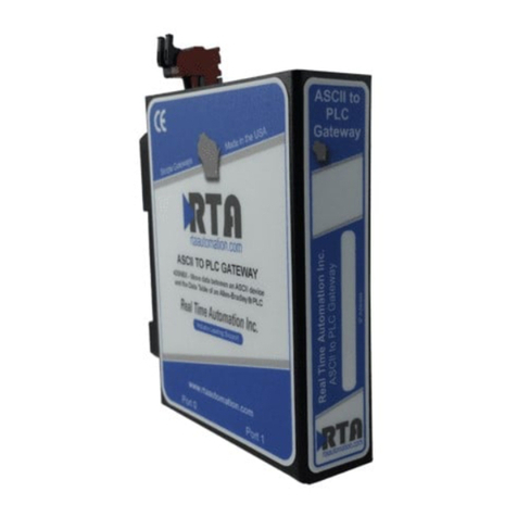
Microcyber G0310 User manual

G0310
Modbus to HART gateway
User Manual

http://www.microcyber.cn/en
~I~
Warning
1. Please don’t take off/install gateway at random.
2. Please check if the power of temperature board set meets the power request in the User Manual.

http://www.microcyber.cn/en
~II ~
Company Introduction
Microcyber Inc. established as a high-tech enterprise by the Shenyang Institute of Automation Chinese
Academy of Sciences, mainly engages in advanced industrial control systems, equipments, instruments and chips
for industrial process automation control solutions in the research, development, production and application.
Microcyber undertakes a number of national scientific and technical key task and “863” project, and has Liaoning
Province networked control systems engineering research center. The company successfully developed the FF H1
fieldbus protocol stack which is number one to be approved internationally in China, and the Industrial Ethernet
Protocol(HSE) which is number one to be approved in China, and the domestic first fieldbus instrument which has
a function of national-level intrinsically safe explosion--proof and safety barrier. Also Microcyber participated in
the drafting of the domestic first Ethernet-based industrial automation protocol standards (Ethernet for Plant
Automation, EPA). As a result, serial products are composed of configuration, control software, embedded
software, control system, instrument chip to the OEM board, and make Microcyber be an industrial automation
products provider in full range, and also further Microcyber’s leading position in the field of fieldbus technology.
Microcyber is the member of FCG and the Profibus National Organization (PNO).
Microcyber passes the Authentication of ISO 9001 Quality System, and has an outstanding innovative R&D team,
plentiful practical experiences of design of the Automatic engineering, a leading product series, a huge market
network, a strict quality management system and an excellent enterprise culture. All these further a solid
foundation of entrepreneurship and sustainable development for Microcyber.
Microcyber Inc. is looking forward to the long-term smooth and close cooperation with you.

http://www.microcyber.cn/en
~III ~
Contents
Chapter 1 Overview................................................................................................................................................................ 1
1.1 Dimension..................................................................................................................................................................... 1
1.2 Structure....................................................................................................................................................................... 1
Chapter 2 Installation..............................................................................................................................................................2
2.1 Wiring............................................................................................................................................................................2
2.2 Jumper configuration....................................................................................................................................................2
2.3 Internal load resistance.................................................................................................................................................3
2.4 Recalibration................................................................................................................................................................. 3
Chapter 3 Working Principle................................................................................................................................................... 4
Chapter 4 Menu Tree.............................................................................................................................................................. 5
Chapter 5 Transmitter Configuration...................................................................................................................................... 6
5.1 Topological Connection.................................................................................................................................................6
5.2 Configuration tool.........................................................................................................................................................7
5.2.1 Installation and activation..................................................................................................................................... 7
5.2.2 Introduction of main page features.......................................................................................................................9
5.3 Basic operations..........................................................................................................................................................11
5.4 Device operation.........................................................................................................................................................14
5.5 Gateway Parameter Setting........................................................................................................................................ 19
5.5.1 Mode selection.................................................................................................................................................... 19
5.5.2 Coil calibration..................................................................................................................................................... 20
5.5.3 Register Calibration............................................................................................................................................. 21
5.5.4 Factory reset setting............................................................................................................................................ 21
5.5.4.1 Reset to Factory Default................................................................................................................................................... 21
5.5.4.2 Save to factory settings.....................................................................................................................................................22
5.5.4.3 Reset to factory settings................................................................................................................................................... 23
5.5.4.4 Device variable assignment.............................................................................................................................................. 24
5.5.5 Modbus variable configuration........................................................................................................................... 25
5.5.5.1 Address............................................................................................................................................................................. 25
5.5.5.2 baud rate...........................................................................................................................................................................25
5.5.5.3 Data bits............................................................................................................................................................................26
5.5.5.4 Calibration.........................................................................................................................................................................26
5.5.5.5 Stop Bits............................................................................................................................................................................26
5.5.5.6 CRC byte order..................................................................................................................................................................26
5.5.5.7 Time frame interval.......................................................................................................................................................... 27
5.5.6 Device Status Configuration................................................................................................................................ 27
5.5.6.1 Register address................................................................................................................................................................27
5.5.6.2 Bit mode........................................................................................................................................................................... 27
5.5.7 PV Range Setting..................................................................................................................................................27
5.5.7.1 PV Range Source...............................................................................................................................................................27
5.5.7.2 PV range operation mode.................................................................................................................................................28
5.5.7.3 Register data type.............................................................................................................................................................28
5.5.8 Device Variable.................................................................................................................................................... 28
5.5.8.1 Type.................................................................................................................................................................................. 28
5.5.8.2 Unit................................................................................................................................................................................... 29
5.5.8.3 Upper limit of sensor range..............................................................................................................................................29
5.5.8.4 Lower limit of sensor range.............................................................................................................................................. 29
5.5.8.5 Minimum span..................................................................................................................................................................29
5.5.8.6 Range limit........................................................................................................................................................................30
5.5.8.7 Lower range limit..............................................................................................................................................................30
5.5.8.8 Default units..................................................................................................................................................................... 30
5.5.8.9 Modbus functional code...................................................................................................................................................31
5.5.8.10 Register address..............................................................................................................................................................31
5.5.8.11 Register data type...........................................................................................................................................................31
5.5.8.12 Scaling factor.................................................................................................................................................................. 31
5.5.8.13 Range Upper Limit Register Address.............................................................................................................................. 32
5.5.8.14 Range Lower limit register address................................................................................................................................ 32
Chapter 6 Quick configuration.............................................................................................................................................. 33
Chapter 7 Maintenance........................................................................................................................................................ 34

http://www.microcyber.cn/en
~IV ~
Chapter 8 Technical Specification......................................................................................................................................... 35
Chapter 9 Appendix1 G0310 MODBUS to HART Gateway Model Selection........................................................................ 36

http://www.microcyber.cn/en
~1~
Chapter 1 Overview
G0310 Modbus to HART Gateway, designed by Microcyber Corporation is a gateway device for Modbus-RTU
protocol and HART protocol. As Modbus master, G0310 Modbus to HART Gateway communicates with devices
that have Modbus-RTU communication function via RS485 interface. It can convert device data to HART device
variables output, and it also supports 4~20mAcurrent output. As shown in Figure 1.1:
Figure 1.1 Modbus to HART gateway
1.1 Dimension
Figure1.2 Dimension (Unit:mm)
1.2 Structure
1
2
4
3
Figure1.3 structure
1Upside
Housing
2Bottom
Housing
3Communic
ation
4 Terminal

http://www.microcyber.cn/en
~2~
Chapter 2 Installation
The dimension of G0310 Modbus to HART gateway is 99*22.5*114.5mm. It supports with standard DIN Rail
installation.
2.1 Wiring
G0310 Modbus to HART gateway terminal distribution and meaning are shown as in Figure 2.1
124V- 224V+
3NC 4NC
5A+ 6B-
7GND 8GND
9HART+ 10 HART-
11 Shield 12 EARTH
13 R14 R
15 24V- 16 24V+
Figure 2.1
The power supply of G0310 MODBUS to HART gateway is HART bus, and 485 communication need external 24V
power supply. The recommended is TP cable, and it shall improve device’s anti-electromagnetic interference
ability. G0310 MODBUS to HART gateway connection diagram is shown as in Figure 2.2:
24VDC Power
PC
HART
Modem
Resistance
+
-
5
6
1
2
9
10
Ampere
meter +
Modbus
device
RS485
communication
A+
B-
GND
-
7
24VDC power
supply
G0310 MODBUS to
HART Gateway
Figure 2.2 G0310 MODBUS to HART gateway connection diagram
2.2 Jumper configuration
G0310 MODBUS to HART Gateway has 2 jumpers, as shown on Figure 2.3. the left one is failure warning current
setting and the right one is configuration protection setting jumper.
Failure Warning Jumper Setting
G0310 MODBUS to HART Gateway has self-diagnostic function.Once failure is detected, intelligent
instrument will output warning current automatically. Warning current mode is decided by JP1 Low (in green

http://www.microcyber.cn/en
~3~
color) on the left of the boar as shown in the figure2.3. When there’s no insertion or insertion of two points
underside, it’s high-level warning (warning current≥21.75mA);When it’s the insertion of two points upside, it’s
low-level warning (warning current≤3.7mA).
Configuration Protection Jumper Setting
G0310 MODBUS to HART Gateway provides jumper setting of device configuration protection by JP1 WrD(in
red color) as shown in the Figure 2.3. When it’s the insertion of two points upside, it’s configuration protection. At
this moment no change of device configuration is allowed. It is allowed when there’s no insertion or insertion of
two points underside.
WrD
Writes enabled
Writes disabled
Low
WrD
JP1
High Alarm
Low Alarm
Low
Figure 2.3 G0310 MODBUS to HART gateway jumper
Saturation fixed output (manufacturer setting, no configuration)
When HART intelligent instrument is running, it will compare PV and range upper and lower limiting value
constantly. When PV exceeds the limit, instrument will output fixed current. When PV is higher than upper limit, it
output 20.8mA;When PV is lower than upper limit, it output 3.8mA.
2.3 Internal load resistance
Terminal 13 and 14 connects 250ΩInternal load resistance, which has no connection with internal circuit. User
can use Internal load resistance to replace resistance in Figure 2.2. Then HART Modem can connect on terminal 13
and 14.
2.4 Recalibration
Users can make a recalibration on G0310 Modbus to HART gateway at test room or installation site before it
was put into application. The operation process is shown as in the Figure 2.4.
start
recalibra-
tion
at the test
room
industrial unit
Setup
:
measuring range
output mode
damping period
conform to
technology
parameters
jumper check
installation
:
installation
configuration
operation
maintenance
no
No
yesyes
Figure 2.4 recalibration process map
G0310 Modbus to Hart gateway is mainly about functional verification. Please refer to the relevant chapters
below for specific verification.

http://www.microcyber.cn/en
~4~
Chapter 3 Working Principle
G0310 MODBUS to HART Gateway supports 4 dynamic variables, 6 device variables.Via MODBUS register, the
data selected by MODBUS device is configured to device variables of G0310 MODBUS to HART Gateway, and then,
it enters the mapping from device variable to dynamic variable, as the device output, supporting 4~20mA analog
signal output.G0310 MODBUS to HART Gateway functional block diagram is shown as Figure 3.1:
MODBUS
REGISTER
MODBUS
Device
Configure Input Channel
Data Type
Register Addr
Unit
0
1
2
3
4
5
Device Variable
G0310 Modbus to HART
gateway
PV
SV
TV
QV
Dynamic Variable
Mapping from Device Variable to
Dynamic Variable
Control System
Process Varable
Analog
Channel
Process
Connection
Figure 3.1 G0310 MODBUS to HART Gateway functional block diagram

http://www.microcyber.cn/en
~5~
Chapter 4 Menu Tree
Basic info
1 device
2 identification
3 version
device configuration
1 output variable
2 sensor info
3 main variable output
4 PV setting
G0310 setting
1 basic info
2 device configuration
3 current calibration
4 variable mornitor
5 gateway configuration current calibration
1 fixed output
2 calibration
variable monitor
1 dynamic variable
2 statistics
gateway configuration
1 coil calibration
2 register calibration
3 reset
4 variable assignment
5 Modbus configuration
6 status configuration
7 PV configuration
8 variable configuration
PV setting
1 URV
2 LRV
3 variable zero
statistics
1 success
2 retry
3 fault
4 sent
version
1 general command
2 device version
3 hardware version
4 software version
dynamic variable
1 first variable
2 current value
3 percent
4 second variable
5 third variable
6 fourth variable
output variable
1 PV
2 SV
3 current
4 percent
identification
1 manufacturer
2 device type
3 device ID
4 long address
senso info
1 serial
2 upper limit
3 lower limit
4 the minimum span
coil calibration
1 read coil
2 read discrete input
3 write single coil
register calibration
1 read hold register
2 write register
variable configuration
1 sensor configuration
2 variable configuration
Device
1 address
2 message
3 description
4 label
5 date
6 assembly mark
7 alarm select
8 protection
9 manufacture ID
Variable assignment
1 main variable
2 second variable
3 third variable
4 fourth variable
device status configuration
1 register address
2 Bit mode
PV range setting
1 PV range source
2 PV range operation mode
3 register data type
Modbus variable configuration
1 address
2 Baud Rate
3 data bits
4 validation
5 stop bits
6 CRC byte order
7 interframe space
sensor parameter
1 type
2 unit
3 upper limit
4 lower limit
5 the minimum span
6 URV
7 LRV
device variable parameter
1 default unit
2 Modbus function code
3 register address
4 register data type
5 scale factor
6 range upper limit register address
7 range lower limit register address
main variable output
1 damping value
2 unit
3 URV
4 LRV
5 transfer function
1
2
3
4
5
1-3
2-1
2-4
4-1
4-2
1-1
1-2
2-2
2-3
5-1
5-2
5-7
5-6
5-5
5-4
5-3 reset
1 restore to factory default
settings
2 save to factory Settings
3 restore to factory settings
5-8-1
5-8-2
5-8
Figure 4.1 menu tree

http://www.microcyber.cn/en
~6~
Chapter 5 Transmitter Configuration
5.1 Topological Connection
The connection mode of HART transmitters can be divided into point-to-point connection and multi-point
connection.
point to point connection
Figure 5.1 HART Point-to-point connection
Features:
1) It can be connected to the upper control system through the AI input module or HART
communication device;
2) Mixing of analog and digital communications;
3) Device address is 0.
multi-point connection
Figure 5.2 HART Multi-to-point connection
Features:
1) Connected to the upper control system through HART communication device;
2) Use HART system's digital capabilities only, the current is fixed at 4mA;

http://www.microcyber.cn/en
~7~
3) Support up to 15 devices in short address format.
5.2 Configuration tool
5.2.1 Installation and activation
The PC software of G0310 is design and development by Microcybe, the installation method is shown as follow:
1. First double-click to install the setup as shown in the Figure 5.3:
Figure 5.3 setup
2. Click “next” to the installation page as shown in the Figure 5.4:
Figure 5.4 installation
3. Select installation path as shown in the Figure 5.5:
Figure 5.5 installation

http://www.microcyber.cn/en
~8~
Figure 5.6 installation
Figure 5.7 installed
The HARTMPT icon will appear on the desktop after the installation is complete as shown in the Figure5.8:
Figure 5.8 PC software
After the installation is complete, it goes directly to the system as shown in the Figure 5.9:

http://www.microcyber.cn/en
~9~
Figure 5.9 system interface
5.2.2 Introduction of main page features
The configuration tool can be started by executing the shortcut of this software on the desktop or in the start
menu. After the configuration tool is started, the interface and the main windows are shown in Figure 5.10.
Figure 5.10 Main interface
1 Menu Bar 2 Toolbar
3 Network view 4 Tabular View
5 Alarm window 6 Status bar
The following outlines the functions of each part.
i. Menu Bar
File (F)
The user executes the menu "File"“ exit ”or clicks the close button in the upper right corner of the window to
exit the configuration tool.
Execute the menu“File” “exit”or click the close button in the upper right corner of the window to exit the
configuration tool.
View (V)
Users can manually refresh or stop refreshing the current tab page by viewing the “refresh” and “stop” features

http://www.microcyber.cn/en
~10 ~
in the menu.
View menus also feature display and hide alarm windows and send commands.
Device (D)
By "on-line "," stop on-line ", you can search any online devices in the network. To use this feature, cancel
"Display Online Only ".
"Display only online" feature, can be configured in the network view, whether to display the device not online.
The default is to display only online devices.
View (V)
You can set whether to hide the toolbar and status bar.
Setting (S)
Execution menu "Settings" “language” configurable configuration tool language, currently support Chinese,
English.
Execute menu "set" “serial port parameters " set the communication port. Default communication port is
serial port 1(COM1).
Help (H)
set the communication port. Default communication port is serial port 1(COM1).
ii. Tool Bar
As shown in Figure 5.10, the toolbar contains four functions: searching online devices, stopping searching
devices, refreshing, and stopping refreshing.
Figure 5.11 tool bar
"search online device","stop search device"function”, are like "on line","stop on line", details are shown in
5.2.2.1 device (D).
“Refresh” function is to refresh the current tab page manually.
“Stop Refresh” function is to stop the action being refreshed.
iii. Network view
the network view contains a list of networks and devices.
The serial port node in the network view COM1, represent the configuration tool connected to the HART
network through the COM1 serial port.
In the menu bar, click “device”“only online devices”, to cancel“only online devices”. At this point, the network
will display 16 unconnected devices, arranged in polling address order.
The unlisted device icon is gray, the online device icon is yellow, and the device icon will flicker in search.

http://www.microcyber.cn/en
~11 ~
Figure 5.12 16offline devices
iv. Tabular View
Different tabs appear depending on the nodes selected by the network view.
When the serial port node is selected, the device list and the main variable scan tab are displayed.
When any device node is selected, the relevant tabs of the device are displayed, such as basic information,
configuration information, sensor configuration, current calibration, and special commands.
v. Alarm window
Users can view some special states of the current device through this window. The alarm window only
corresponds to the last correctly accessed device.
vi. Status bar
Displays the status of the current operation according to the operation.
5.3 Basic operations
i. Set up serial port
When starting, the default communication port is serial port 1. If the user's serial line is not connected to serial
port 1 or serial port 1 is occupied or damaged, the serial port needs to be reset.
After startup, if the user does not operate, the configuration tool will not automatically send any commands to
the serial port.
Figure 5.13 serial port setting
Set the serial port dialog box as shown in Figure 5.13. The list can list the serial port available on the current
computer. After the user selects the target serial port, press OK button to set up, set up success or failure have
prompt information. Press the Cancel button to exit the window.

http://www.microcyber.cn/en
~12 ~
If the serial port setting fails, select again. Serial port setting failure, can not carry out communication
operation.
ii. Device Scan
Configuration tools only support user access to online devices, so you need to query which devices are currently
online. Query methods can be divided into three categories:
(1) Single node search: according to the polling address of the target device, find whether the specified
device is online;
(2) Full search: search for all devices with polling addresses 0 to 15.
(3) Custom search: search for the specified device address.
If the device is online, the device list tab in the network view and tab view lists the brief information of the
device.
Methods of single node search:
Click on the right mouse button on the serial node of the network view and select a "single node "a “node”
(for example: node 0).
Figure 5.14 Right-click convenient search menu
Full search:
Click the right mouse button on the serial node of the network view and select "Full Search " (e.g. COM1)
Custom search methods:
Since in the network view, only online devices are displayed by default, the search can not be customized. To
use a custom search, cancel only the online device.
In the menu bar, click “device”“only online device”. cancel only online features.
Figure 5.15 device selection
At the moment, the network view will display 16 devices with addresses (gray icons). After selecting the device
that needs to be searched, click search online device , or click menu bar "device ""online ".
During the search process, you can click stop search device (or menu bar "device" “stop online") to
abort the current search.
The device on line is a yellow icon to distinguish the gray icon without the online address. Online device naming:

http://www.microcyber.cn/en
~13 ~
the device label +@+ the device polling address.
iii. Send command
Click “view” “send command” on the menu bar to view send commands and call out the send command
window, as shown inFigure 5.16.
By this function, users can send all supported HART general commands, general behavior commands, special
commands.
The data to be sent must be hexadecimal.
Figure 5.16 send command
Sending commands requires understanding the frame format of each command, so it is only applicable to
senior users and R & D personnel.
iv. Multilingual support
The configuration tool will select the appropriate language package according to the language settings of the
current operating system at the first start, so that the user will not have a language barrier. If the user wants to use
other languages, you can select the supported language in the language in Settings, as shown in Figure 5.17.
Figure 5.17 Language settings

http://www.microcyber.cn/en
~14 ~
5.4 Device operation
i. list of device
The device list tab displays summary information for all searched online devices. for example: polling address,
device label, vendor, device type, ex-factory date, etc.
Method 1 to enter the Device List tab:
After searching the online device, the default recovery displays the device list tab.
Method 2 to enter the Device List tab:
(1) Click on the left mouse button in the network view serial node (for example: COM1), the right tab view
shows the serial port connected to the network of all online device related tab information.
(2) Click on the "device list" in the right tab view, and if the information is obtained successfully, the
summary information of all searched online devices is displayed, as shown in Figure 5.18.
Figure 5.18 Device List tab
ii. Main variable monitoring
It shows the trend curve for all online device main variables. Transverse time axis, longitudinal numerical axis,
can be adjusted.
Method to enter the main variable scan tab:
(1) Click on the left mouse button in the network view serial node (for example: COM1), the right tab view
shows the serial port connected to the network of all online device related tab information.
(2) Click "main variable Monitoring" in the right tab view, as shown in Figure 5.19.

http://www.microcyber.cn/en
~15 ~
Figure 5.19 Main variable monitoring tab
iii. Basic Info
Users can obtain and configure basic information about online devices.
Method to access the Basic Information tab:
(1) The left mouse button clicks on an online device in the network view, and the right tab view displays the
tabs associated with the device.
(2) Click "basic information" in the right tab view, and if the information is obtained successfully, the basic
information of the device is displayed, as shown in Figure 5.20.
Figure 5.20 Basic information tab
The basic information tab contains the following table:
Functional
description
Whether to
modify
Remarks
Address
Yes
polling
address,
selection
range
0~15
Message
Yes
Up
to
32
characters
Description Yes Up to 16 specified characters
Label Yes Maximum length of 8 specified characters
Date
Yes
From
1900
to
2155
Assembly
Number
Yes Must be 6 decimal places
Alarm
selection
No Display hardware alarm selection mode ," high
alarm "/" low alarm "
Writing
protection
No Display hardware write protection options, NO
"/" YES"
ID of
manufacturers
No Trademark issuer code, hexadecimal
Table of contents
Other Microcyber Gateway manuals
Popular Gateway manuals by other brands
Alcatel-Lucent
Alcatel-Lucent OmniAccess 5321 BG Specifications
ICP DAS USA
ICP DAS USA GW-7553 Quick start user guide

PheeNet
PheeNet WMS-208 Quick installation guide
Mennekes
Mennekes eMobility-Gateway Professional+ OPERATING AND INSTALLATION Manual
Verizon
Verizon GT784WNV user manual
CommScope
CommScope Touchstone TG6452 user guide

VPNet
VPNet VSU 5000 user guide

ZyXEL Communications
ZyXEL Communications p-2302r series Specifications

Foxconn
Foxconn IOTGW-TIX01 user manual

AudioCodes
AudioCodes M500L Hardware installation manual
VIA Technologies
VIA Technologies ARTiGO A820 quick start guide

AudioCodes
AudioCodes Mediant Series Quick setup guide
