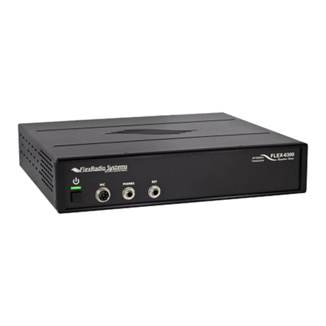
FlexRadio Systems SDR-1000 User manual

SDR-1000
OPERATING MANUAL
Ver sion 1.8.0

S D R - 1 0 0 0 S O F T WA R E D E F I N E D R A D I O
Operating Man al
FlexRadio Systems
12100 Technology Boulevard • Austin, TX 8 2
Phone: (512) 250-8595 • Fax: (512) 233-5143
Email: sales@flex-radio.com
Editor: Joe de Groot – AB1DO
iFlexRadio Systems

Table of Contents
PREFACE......................................... ..........................................VIII
ACKNOWLEDGEMENTS................................................................ .X
1 GENERAL DESCRIPTION.............................................................1
2 SPECIFICATIONS................................................................. ........2
3 HARDWARE CONFIGURATION.....................................................3
STANDARD CONFIGURATION....................................................................................................... 3
High Performance Receiver Preamplifier............................................................................................... 3
Fifth Order Low Pass Filters..................................................................................................................3
Enhanced 1W PEP Driver..................................................................................................................... 4
28MHz Transverter IF Takeoff..............................................................................................................4
Experimental Impulse Generator........................................................................................................... 4
Enclosure..............................................................................................................................................4
UPGRADES..........................................................................................................................................
2 Meter Transverter...............................................................................................................................5
100W Power Amplifier......................................................................................................................... 5
Specifications........................................................................................................................ ........................5
Automatic Antenna Tuning Unit............................................................................................................6
Griffin PowerMateTM VFO Tuning Knob............................................................................................ 6
Contour Designs Shuttle Pro V.2........................................................................................................... 6
External Clock Reference Option..........................................................................................................
USB To Parallel Adapter.......................................................................................................................
4 PLUG PINOUTS...........................................................................8
EXTERNAL CONTROL CONNECTOR (X2)....................................................................................8
Push To Talk (PTT) Input..................................................................................................................... 9
Mute Receiver...................................................................................................................................... 9
External Linear Amplifier Keying......................................................................................................... 9
ii FlexRadio Systems

T A B L E O F C O N T E N T S
Universal Controller Board for Antenna and Transverter Control............................................................9
ENCLOSURE MICROPHONE CONNECTOR............................................................................... 10
KEYER INPUT................................................................................................................................... 11
5 HARDWARE SETUP...................................................................12
6 SOFTWARE INSTALLATION & SETUP........................................18
INSTALL LATEST SOUND CARD DRIVERS................................................................................19
UPGRADING FROM AN EARLIER VERSION..............................................................................19
POWERSDR EXECUTABLE INSTALLATION............................................................................. 19
POWERSDR SETUP WIZARD.........................................................................................................24
SOUND CARD SETUP.......................................................................................................................34
POWERSDR CALIBRATION...........................................................................................................3
Frequency Calibration – DDS Clock Adjustment................................................................................. 36
Auto Calibration............................................................................................................................ ..............36
Manual Calculation................................................................................................................. ....................36
Level Calibration – Spectrum & S-Meter............................................................................................. 36
Image Null Calibration ....................................................................................................................... 3
Automatic Calibration .................................................................................................................... .............37
Manual Adjustment....................................................................................................................... ...............37
AUTOMATIC AMPLIFIER GAIN CALIBRATION.......................................................................37
7 FRONT CONSOLE......................................................................40
(1) VFO A............................................................................................................................................ 42
(2) TUNING CONTROLS.................................................................................................................. 42
(3) VFO B.............................................................................................................................................43
(4) MULTIMETER............................................................................................................................. 43
RX Meters.......................................................................................................................................... 43
TX Meters.......................................................................................................................................... 44
( ) BAND SELECTION & BAND STACKING MEMORIES..........................................................4
(6) MODE SELECTION.....................................................................................................................47
(7) FILTER CONTROLS................................................................................................................... 48
Labeled Filter Buttons......................................................................................................................... 48
Variable Filter Buttons........................................................................................................................ 49
(8) MODE SPECIFIC CONTROLS................................................................................................... 0
Phone Controls ...................................................................................................................................50
CW Controls.......................................................................................................................................51
Digital Controls...................................................................................................................................53
(9) DISPLAY CONTROLS................................................................................................................. 3
Panadapter View Controls................................................................................................................... 54
Display Type Controls.........................................................................................................................55
Display Type Descriptions.................................................................................................................. 55
Spectrum..................................................................................................................................... ................56
Panadapter (Panoramic Adapter)................................................................................................. ................56
Histo ram............................................................................................................................... ....................57
iii FlexRadio Systems

T A B L E O F C O N T E N T S
Waterfall..................................................................................................................................................... .58
Scope...................................................................................................................................... ....................58
Phase............................................................................................................................................. .............59
Off...................................................................................................................................... ........................59
Cursor and Peak Position........................................................................................................................ .....60
(10) SUB-RX CONTROLS..................................................................................................................61
(11) DSP CONTROLS.........................................................................................................................61
(12) VFO CONTROLS........................................................................................................................62
(13) CPU %..........................................................................................................................................63
(14) POWER (STANDBY/ON)........................................................................................................... 63
(1 ) MON (MONITOR)...................................................................................................................... 6
(16) MOX (MANUALLY OPERATED TRANSMIT).......................................................................6
(17) MUT (MUTE).............................................................................................................................. 6
(18) X2TR............................................................................................................................................ 6
(19) ATU MODES............................................................................................................................... 66
(20) TUN (TUNE)................................................................................................................................ 66
(21) AF (AUDIO FREQUENCY GAIN).............................................................................................66
(22) RF (RADIO FREQUENCY GAIN).............................................................................................67
(23) DRIVE (TRANSMITTER POWER OUTPUT/TUNE POWER).............................................. 67
(24) AGC (AUTOMATIC GAIN CONTROL)...................................................................................67
(2 ) PREAMP......................................................................................................................................69
(26) SQL (SQUELCH)........................................................................................................................ 69
(27) DATE/TIME DISPLAY...............................................................................................................70
(28) SETUP FORM............................................................................................................................. 70
(29) – (33) OPERATING FORMS..................................................................................................... 70
8 SETUP FORM.................................................................. ...........71
GENERAL TAB..................................................................................................................................72
Hardware Config Sub-Tab.................................................................................................................. 2
Radio Model................................................................................................................................................................ 2
Hardware Setup............................................................................................................................................................ 3
DDS............................................................................................................................................................................. 4
Options Sub-Tab................................................................................................................................. 5
Options........................................................................................................................................................................ 6
Process Priority............................................................................................................................................................ 6
Update Notification......................................................................................................................................................
Click Tune Offsets (Hz)................................................................................................................................................
Auto Mute....................................................................................................................................................................
Main Console (Always On Top)................................................................................................................................... 8
Keyboard..................................................................................................................................................................... 8
Calibration Sub-Tab............................................................................................................................ 9
Freq Cal....................................................................................................................................................................... 9
Level Cal..................................................................................................................................................................... 9
RX Image Reject Cal...................................................................................................................................................80
Filters Sub-Tab................................................................................................................................... 80
AUDIO TAB........................................................................................................................................81
Sound Card Sub-Tab...........................................................................................................................81
Sound Card Selection...................................................................................................................................................81
iv FlexRadio Systems

T A B L E O F C O N T E N T S
Buffer Size...................................................................................................................................................................82
Sample Rate.................................................................................................................................................................82
Line In Gain.................................................................................................................................................................82
Mic In Gain..................................................................................................................................................................82
Latency........................................................................................................................................................................82
Output Voltage.............................................................................................................................................................82
Sound Card Setup Details.............................................................................................................................................83
VAC Sub-Tab.....................................................................................................................................84
Gain (dB).....................................................................................................................................................................85
Auto Enable.................................................................................................................................................................85
DISPLAY TAB....................................................................................................................................86
Spectrum Grid..............................................................................................................................................................86
Refresh Rates...............................................................................................................................................................8
Waterfall......................................................................................................................................................................88
Multimeter...................................................................................................................................................................89
Phase Resolution..........................................................................................................................................................89
Scope Time Base..........................................................................................................................................................89
Averaging....................................................................................................................................................................89
Polyphase FFT.............................................................................................................................................................90
DSP TAB............................................................................................................................................. 90
Options Sub-Tab.................................................................................................................................90
Noise Reduction...........................................................................................................................................................91
Automatic Notch Filter.................................................................................................................................................91
Buffer Size...................................................................................................................................................................92
Noise Blanker..............................................................................................................................................................92
Noise Blanker 2 ...........................................................................................................................................................93
Image Reject Sub-Tab.........................................................................................................................96
Receive Rejection........................................................................................................................................................96
Transmit Rejection.......................................................................................................................................................9
Keyer Sub-Tab....................................................................................................................................98
CW Pitch.....................................................................................................................................................................98
Connections...............................................................................................................................................................100
Options......................................................................................................................................................................100
Signal Shaping...........................................................................................................................................................101
Semi Break In............................................................................................................................................................101
AGC/ALC Sub-Tab.......................................................................................................................... 102
AGC..........................................................................................................................................................................102
Leveler.......................................................................................................................................................................103
ALC...........................................................................................................................................................................103
TRANSMIT TAB.............................................................................................................................. 104
TX Profiles................................................................................................................................................................105
Transmit Filter............................................................................................................................................................105
Noise Gate.................................................................................................................................................................106
VOX..........................................................................................................................................................................106
TX Monitor................................................................................................................................................................10
Compression..............................................................................................................................................................10
AM Carrier Level.......................................................................................................................................................108
PA SETTINGS TAB..........................................................................................................................109
Gain By Band (dB).....................................................................................................................................................109
EXT. CTRL TAB.............................................................................................................................. 110
APPEARANCE TAB ....................................................................................................................... 111
Display Sub-Tab............................................................................................................................... 111
vFlexRadio Systems

T A B L E O F C O N T E N T S
Overall Display..........................................................................................................................................................111
Cursor/Peak Readout..................................................................................................................................................112
Panadapter..................................................................................................................................................................112
General Sub-Tab............................................................................................................................... 113
VFO...........................................................................................................................................................................114
Band Data..................................................................................................................................................................114
Meter Sub-Tab.................................................................................................................................. 115
Original Style.............................................................................................................................................................116
Edge Style..................................................................................................................................................................116
KEYBOARD TAB............................................................................................................................ 117
CAT CONTROL TAB...................................................................................................................... 118
Cat Control ................................................................................................................................................................119
PTT Control...............................................................................................................................................................120
Test............................................................................................................................................................................121
TESTS TAB.......................................................................................................................................122
TX IMD Text:............................................................................................................................................................122
Audio Balance Test....................................................................................................................................................122
X2..............................................................................................................................................................................123
Impulse Test...............................................................................................................................................................123
Signal Generator........................................................................................................................................................123
9 OPERATING FORMS............................................................. ....124
(29) MEMORY FORM..................................................................................................................... 12
Save… .............................................................................................................................................125
Recall…........................................................................................................................................... 126
(30) WAVE FORM............................................................................................................................127
Playback....................................................................................................................................................................12
Playlist.......................................................................................................................................................................129
Record.......................................................................................................................................................................129
TX Gain (dB).............................................................................................................................................................129
Record Options................................................................................................................................. 129
Receive......................................................................................................................................................................130
Transmit.....................................................................................................................................................................130
(31) EQUALIZER FORM.................................................................................................................130
(32) XVTRS FORM...........................................................................................................................131
(33) CWX FORM.............................................................................................................................. 132
Standard CWX Controls....................................................................................................................132
CWX Memories............................................................................................................. ............................133
Special Characters.......................................................................................................................... ...........133
Keyboard and Extended Controls.......................................................................................................134
Extended CWX Controls................................................................................................................ .............134
Morse Definition Editor......................................................................................................................... .....136
10 OPERATION................................................... ........................137
POWER-UP PROCEDURE............................................................................................................. 138
POWER-DOWN PROCEDURE...................................................................................................... 138
TUNING METHODS........................................................................................................................140
Spectrum Dra and Click.................................................................................................. .........................140
vi FlexRadio Systems

T A B L E O F C O N T E N T S
Mouse Wheel............................................................................................................................. ................140
Mouse Wheel Hover....................................................................................................................... ............140
Spectrum Click Tunin ..................................................................................................... ..........................140
Keyboard Keys........................................................................................................................................ ...141
USB Tunin Knob.................................................................................................................. ....................141
VOICE TRANSMISSION OPERATION........................................................................................ 142
CW TRANSMISSION OPERATION.............................................................................................. 14
Initial Settings................................................................................................................................... 146
Internal Keyer................................................................................................................................... 14
External Keyer.................................................................................................................................. 148
CWX Form.......................................................................................................................................149
Third Party Program..........................................................................................................................151
DIGITAL MODE OPERATION......................................................................................................1 4
CAT Control Setup........................................................................................................................... 158
Install VCOM..................................................................................................................... .......................158
Confi ure the VCOM Port Pairs............................................................................................... ..................164
Confi ure PowerSDR CAT Control........................................................................................... ..................166
Confi ure PowerSDR Keyer Connections........................................................................................... .........167
Virtual Sound Connection................................................................................................................. 168
Create the Virtual Audio Cables............................................................................................... ...................168
Setup VAC in PowerSDR........................................................................................................... .................169
Setting up Third Party Digital Programs.............................................................................................169
Usin MixW with PowerSDR............................................................................................................. .........170
Pro rams Needin to Connect to the Default Sound Device........................................................... ...............175
ATU (ANTENNA TUNING UNIT) OPERATION.......................................................................... 177
11 TROUBLESHOOTING.............................................................179
The software is oscillating quickly between receive and transmit modes..............................................1 9
Relays do not click when starting the software or when cycling the software power button.................. 1 9
Relays click, but I have no audio........................................................................................................184
Relays click and I hear static, but no signals....................................................................................... 18
I hear signals, but they sound chopped up, like a motorboat................................................................ 18
I hear signals, but cannot null the image............................................................................................. 188
The signals are all off frequency........................................................................................................ 189
The noise hiss when no signals are present is fatiguing....................................................................... 189
Software does not respond to PTT signals.......................................................................................... 189
The receiver works great, but I am getting no output power................................................................ 191
I am getting some power out, but the power seems low (also, see above—no power issue).................. 191
I am getting signal reports that indicate echoing or distortion.............................................................. 192
I am getting signal reports that indicate I am transmitting DSB while in SSB modes............................192
I am getting an error message that says, “Error communicating with ATU.”........................................193
It seems like the ATU is not tuning correctly. Is there a way to check?................................................ 193
I get an error when I try to use my USB Adapter that says “USB Device not found. (-1)”.................... 194
I see a hump around 10kHz below the center line on the display, that doesn’t seem to go away............194
vii FlexRadio Systems

Preface
Welcome to the exciting world of software defined radio. The SDR-1000 software defined transceiver is by
nature ever (rapidly) evolving. It is therefore unlike most other transceivers, which once acquired, rarely if
ever change.
Although the rapid development of the SDR-1000 can be exhilarating, it can also be somewhat daunting.
When first confronted with an SDR-1000 and its PowerSDR™ 1 operating software, the sheer number of
connections, controls, and settings can seem mind boggling even to the most seasoned Ham radio operator.
This operating manual attempts to both guide a user step by step through the setup process (both hardware
and software) and to act as a reference once the radio has been set up. Additionally, the freely downloadable
PowerSDR software will install with default settings that, in most cases, will require little adjustment. Any
adjustments that you make are automatically saved and can be imported into an updated version of the
software.
Due to the nature of the SDR-1000, the largest part of this operating manual, by far, will refer to software.
The operating manual has numerous screenshots of windows and forms to detail the various steps.
Although the manual describes the latest official release of the PowerSDR software, you may occasionally
notice an earlier version identified in the title bar of a screenshot. This is because FlexRadio Systems™ 2 has
decided to only update a screenshot if it changes.
The first three chapters of this manual will give you an overview of the SDR-1000 radio. Chapters 4 and 5
will guide you through the hardware setup, which apart from the connections to the parallel (or USB) port
and sound card of a computer, will not differ much from the transceivers to which you are most likely
already acclimated.
Chapter 6 details the installation of the PowerSDR software and calibration routines. Once completed, you
should be able to engage in your first QSO. For additional guidance on operating the SDR-1000 in various
modes, you may want to refer to chapter 10: Operation. This is especially recommended for operating
digital modes and CW, as this may be somewhat different from what you are accustomed to.
Chapters , 8, and 9 describe in detail the various controls on the Front Console, Setup Form and Operating
Forms respectively. You may want to reference these chapters to familiarize yourself with the exact
functioning of these controls and their often many options and settings.
1 PowerSDR is a trademark of Bronze Bear Communications, Inc.
2 FlexRadio Systems is a registered trademark of Bronze Bear Communications Inc.
viii FlexRadio Systems

P R E F A C E
Finally, chapter 11 is a troubleshooting guide, which should help you through various issues you may face.
If you cannot find an acceptable answer to an issue you may have, please do not hesitate to contact us either
by email or by phone (both found on our website). You may also want to check out our website and its ever
expanding Knowledge Base
If you have any ideas on how to improve the SDR-1000, please feel free to contact us, or better still, to join
our email reflector (see our website for details). Not only is the SDR-1000 a software defined radio; it is
also a user defined radio.
FlexRadio Systems is committed to ensuring that your experience with the SDR-1000 will be one of the
most enjoyable you have with Ham radio.
[The rest of this page has been left blank intentionally]
ix FlexRadio Systems

Acknowledgements
FlexRadio Systems could not be as successful, nor could the SDR-1000 radio be what it is today without
the many selfless contributions of our users all over the world. These contributions have spanned and
continue to span improvements to our hardware and software, ranging from bug reports and feature requests
to actual design and implementation of certain functionality.
Identifying contributors by name would only risk leaving out others with equally valuable contributions.
We therefore wish to suffice with a heartfelt thank you for your support and continued commitment.
[The rest of this page has been left blank intentionally]
xFlexRadio Systems

1
General Description
The SDR-1000 Software Defined Radio is an open-software; 1 or 100W
transceiver providin eneral covera e receive operation with amateur
radio band transmission between 12kHz and 60MHz.
The FlexRadio SDR-1000 is a complete Software Defined Radio (SDR) transceiver designed for Amateur
Radio use. It is the first fully open software transceiver that uses a personal computer (PC) for all Digital
Signal Processing (DSP) and control functions of the radio. General coverage receiver operation is provided
from 12kHz to 60MHz along with transmit capability on all licensed amateur bands within the coverage
range. The theory behind the SDR-1000 is described in detail in a four part QEX magazine series entitled,
“A Software Defined Radio for the Masses1.” The articles are available for download from the FlexRadio
website at www.flex-radio.com. There are also links on the site to other excellent reference materials related
to SDR and DSP theory.
Since its introduction, additional hardware components have been added to further improve the
functionality and performance of the SDR-1000. The PowerSDRTM software, written in C#.NET, provides a
full featured transceiver interface and digital signal processing for the SDR-1000. It is continuously
improved over time through open source enhancements supplied by both customers and FlexRadio
Systems.
The basic hardware consists of four boards in a stack within an enclosure. The hardware provides a LNA,
filters, mixer, power, i/o interfacing and 1W PEP driver. Also provided is a standard interface to the
optional Down East Microwave 2 meter low power transverter (intended for use in VHF, UHF, and
Microwave systems), as well as an interface to the optional 100W power amplifier and the ATU (LDG Z-
100). Additionally available is an optional interface for an external, customer supplied 10 MHz reference
clock oscillator that may provide precision frequency control.
The Contour ShuttlePro v2 USB controller offers the ability to control the radio the way you want to
without having to use a mouse or keyboard. With 15 programmable buttons and 2 concentric tuning dials
(one spring loaded jog dial), this accessory offers an unparalleled level of programmable hardware control.
1 G. Youngblood, “A Software Defined Radio for the Masses: Part 1, Part 2, Part 3, and Part 4,” QEX Jul/Aug 2002, Sep/Oct 2002,
Nov/Dec 2002, and Mar/Apr 2003 respectively.
1FlexRadio Systems
Chapter
1

2
Specifications
(Specifications are subject to change without notice)
Table 1: Specifications
Receiver
Receiver Frequency Range 12kHz-60MHz1
IP3 (2kHz Tone Spacing) +30.3dBm (Preamp MED), 19.3dBm (Preamp HIGH)2
IMD DR3 (2kHz Tone Spacing) 103.5dB (Preamp MED), 100.2dB (Preamp HIGH) 2
MDS -131dBm (Preamp HIGH), -121dBm (Preamp MED) 2
Mini u Tuning Step 1Hz (DDS d wn t µHz)
DDS Clock 200MHz, <1ps RMS jitter
Max. Receive Bandwidth 192kHz (Limited by s und card)
Trans itter
Trans itter Frequency Range 160-6m Bands (2m transverter IF pti nal)
Trans it Power 100W HF 160-10m w/ pti nal amp3, 500mW 6m
Controls
Control Interface PC Parallel P rt (DB-25 c nnect r) r pti nal USB
Rear Panel Control Outputs 15 pin D-c nnect r f r external TR relay and band c ntr l relays
Input Controls PTT f t switch, C de Key, Micr ph ne
Audio Interface Line In, Line Out, Speaker Out, Micr ph ne In
General
Enclosure Di ensions 10" W x 9.5" D x 4.5" H (25.4cm x 24.1cm x 11.4cm)
Power Supply Require ent 13.8VDC @ 1.25A (Max). 25A with pti nal 100W PA4
1 An optional filter bank is supplied that can be configured for bands below 160m. Requires external user supplied pre-selector for best
operation below 160m
2 Sound Card: Edirol FA-66 @ 96kHz sampling rate.
3 40W continuous carrier (100% duty cycle)
4 We recommend the Astron SS-30 or SS-30M or equivalent power supply for the SDR-1000
2FlexRadio Systems
Chapter
2

3
Hardware Config ration
Standard Configuration
High Performance Receiver Preamplifier
The receiver front end incorporates a Sirenza Microdevices SGA-6286 SiGe HBT MMIC amplifier with a
noise figure of less than 2dB. With the INA baseband gain of the SDR-1000 set to 26dB, the overall
receiver noise figure is approximately 4dB. The TRX board also allows 0dB INA gain setting for large
signal handling capability. A 10dB fixed attenuator may be switched in front of the LNA to increase IP3
when needed. Overall there are four gain settings done in hardware to allow you to optimize the front end
for your needs.
The front end of the SDR-1000, provides the following key benefits:
Lower receiver noise figure
Reduces relative strength of DDS local oscillator spurs in relation to the signal of interest
Lowers local oscillator radiation in relation to the signal of interest
Fixed source/load impedance for the filters
Fixed source impedance for the QSD (Quadrature Sampling Detector, IQ Mixer)
Fifth Order Low Pass Filters
Nine 5th order low pass filter banks are provided to cover all amateur bands from 160M-6M. Since the
filters are low pass, general coverage reception is still provided. The filters improve 3rd harmonic rejection
by more than 35dB over the original SDR-1000. There are BPF filters in front of the preamp board (in the
signal chain) to provide overload protection for the LNA. The LNA is then followed by the low pass filters,
which in turn drive the QSD (mixer) on the TRX board. A spare filter bank is provided for user
configuration to allow improved coverage on other bands such as medium wave or VLF bands. While the
SDR-1000 covers frequencies down to 11kHz, additional filtering is required to minimize response to odd
order harmonics. The optional filter bank allows the user to customize the radio to add support for such
frequencies.
3FlexRadio Systems
Chapter
3

H A R D W A R E C O N F I G U R A T I O N C H A P T E R 3
Enhanced 1W PEP Driver
The low power model incorporates a 1W PEP driver amplifier. The driver is between the new front end low
pass filters and the band pass filters on the BPF board, which yields increased harmonic suppression. The
driver circuit also allows for amplifier stability when driving capacitive loads and increases the gain to
reduce sound card drive requirements.
28MHz Transverter IF Takeoff
The RFE provides an internal connector for integration of the Down East Microwave 2M transverter IF
(DEMI144-28FRS). Only a single coax cable is required for both RF and TR control. The SDR1K-ENC
enclosure has mounting holes to allow either common or separate transmit/receive connections for
transverters. You can even set up the SDR-1000 to provide a dual 144/28MHz IF to cover all of the VHF
through microwave bands.
Key features of the DEMI144-28FRS are:
144-146MHz coverage
Unity gain receive conversion
4dB NF maximum
+1 dBm double balanced mixer
Three chamber helical filter
100mW nominal linear output
Experimental Impulse Generator
An experimental circuit has been incorporated that creates a 4.5ns pulse for equalization of the QSD and
sound card quadrature path. DSP software will be written to calculate the impulse response of the circuit
and automatically correct for phase and amplitude imbalances between the channels. In theory, this will
provide dynamic opposite sideband rejection optimization.
Enclosure
The SDR1K-ENC enclosure is designed to accommodate expansion options including the Down East
Microwave 2M IF transverter and the 100W PEP HF linear amplifier and LDG Z-100 automatic antenna
tuning unit options. Rear panel connections are provided for the PC parallel control port, sound card
interface, external control lines, split or common transverter RF connections, and QRP and QRO RF
connections. An AUX mounting hole is provided for the 10MHz reference clock option connector when
precision frequency control is desired.
4FlexRadio Systems

H A R D W A R E C O N F I G U R A T I O N C H A P T E R 3
Upgrades
2 Meter Transverter
The DEM 144-28FRSK is a low power, high performance 144 MHz to 28 MHz transverter kit design to be
used in conjunction with Flex Radio System’s SDR-1000 Software Defined Radio transceiver. It is intended
to be used as a 2nd conversion IF for microwave transverters. The 144-28FRSK has a nominal linear output
power of 50 - 100 mW with the 28 MHz. IF drive provided by the SDR-1000. On the receive side, a high
dynamic range amplifier, a high level double balanced mixer (+1 .0 dBm) and a three chamber helical filter
are employed to providing a over load proof, unity gain front end with superior selectivity. It is the same
design as our high performance 2 meter transverter but without the GaAs FET front end that would provide
excessive system gain not require in a microwave transverter system. The transverter is complete with all
interfacing required to install in the SDR1K-ENC enclosure and operate with the SDR-1000.
The 144-28FRSK’s 144 MHz input/output utilize BNC connectors (supplied in this kit) that are mounted in
the existing holes in the SDR1K-ENC enclosure. The transverter also has a built in relay for external
switching duties if required. It will “Shadow” the TR switch timing of the SDR-1000. The only external
wiring required to operate a microwave transverter after the completion of this kit are a simple BNC cable
or cables that will carry both TX and RX signals along with the keying voltage to activate the microwave
transverters of choice transmit functions. It is a complete, simple to use kit and will provide the highest 2
meter to microwave transverter performance on the market today.
100W Power Amplifier
The SDR-100WPA is a 100 Watt HF linear power amplifier, designed exclusively for installation in SDR-
1000 Software Defined Transceivers. Adding the 100WPA to existing radios required limited kit building
skills including wire/coax preparation, connector assembly, soldering, and mechanical assembly.
Specifications
Power output: 100W PEP, 50W on 60m
Bands: 160, 80, 60, 40, 30, 20, 1 , 15, 12, 10 meters
Elliptical filters on all bands
Drive requirements: <500mW for full output
Output transistors: Rugged matched pair 2SC28 9s
Duty cycle: Designed for intermittent SSB service (40W continuous duty)
Harmonic Content: < -43dBc
Load tolerance: 2:1 SWR or better
5FlexRadio Systems

H A R D W A R E C O N F I G U R A T I O N C H A P T E R 3
Software monitoring: Forward/Reverse Power and SWR
SWR protection: automatic power reduction for SWR > 2:1
DC power requirements: 13.8VDC @ 25A nominal for full output
Internal fuse: 25A automotive mini fuse with reverse polarity protection
Output: BNC 50 Ohm on rear panel
Cooling: 80x80x15mm, 23dB-A fan provided
Internal expansion connections: ATU RF In/Out and control
Automatic Antenna Tuning Unit
The SDR-ATU is a fully integrated automatic antenna-tuning unit across the entire HF range. It will tune
dipoles, verticals, Yagis or virtually any coax-fed antenna. It will match a wide range of antennas and
impedances. Features include:
Microprocessor controlled, switched L tuning network
Automatically matches antennas from 6-800 ohms impedance, or a 10:1 SWR, 3:1 on 6m
Tunes from memory in less than one half second. A full tune will take from 1-6 seconds.
200 memories for almost instant return of previously tuned frequencies.
Continuous coverage from 1.8 to 54 MHz
Power range 0.1 to 125 Watts, 50 Watts on 6m
Griffin PowerMateTM VFO Tuning Knob
The attractive GCN-SLV Griffin Technology PowerMate control knob connects to a USB port to provide
variable-rate VFO tuning for the SDR-1000. A simple click of the knob changes the tuning rate to any of
four user configured tuning rates. It can even be programmed to set the volume by a press, hold, and turn of
the knob. Made of high-quality machined aluminum, PowerMate feels like a solid volume knob pulled right
off the front of a world-class stereo. Its heavy weight and tactile feel are a welcome departure from typical
plastic USB peripherals.
Contour Designs Shuttle Pro V.2
The ShuttlePro V.2’s sleek innovative design, pre-configured for many of today's popular applications,
advanced programmability, and ease of use is in short, the perfect marriage of form and function.
6FlexRadio Systems

H A R D W A R E C O N F I G U R A T I O N C H A P T E R 3
The ShuttlePro V.2 is a powerful productivity enhancement tool for the PowerSDR software. The
ShuttlePro V.2 even comes pre-configured for many of the leading applications. You can also easily
customize the ShuttlePro V.2 for virtually any application.
The ShuttlePro V.2 is designed for ergonomic integrity and maximizing productivity, allowing one-hand
access to the fully programmable buttons and jog/shuttle knob. Nine (9) of the buttons have removable
keycaps for easy labeling and referencing. The inner ring or 'jog' rotates through 360 degrees and provides
precision control. The outer black ring or 'shuttle' is rubberized and spring-loaded. It facilitates tuning and
radio control. You can also use the jog and shuttle for many other purposes such as scrolling, volume
control, and sequencing.
External Clock Reference Option
The SDR-CLK External Clock Reference Option kit provides the connection required to operate the DDS
oscillator from an external 10MHz or 20MHz precision frequency reference. GPS locked oscillators may be
used in this configuration to provide precise frequency control of the SDR-1000. The internal 200MHz
oscillator must be removed to use the external reference clock.
Note: This option requires a customer provided precision clock source not
provided by FlexRadio Systems.
USB To Parallel Adapter
The SDR-USB is a USB to parallel communications adapter, specially designed to control the SDR-1000. It
allows the radio to be used with computers that do not have a parallel port available. The SDR-USB
supports all of the control and status lines required by the SDR-1000 and has special firmware to offload
hardware polling tasks from the PC. A separate download and installation of driver software is required.
[The rest of this page has been left blank intentionally]
7FlexRadio Systems

4
Pl g Pino ts
External Control Connector (X2)
The 15-pin, high-density, female “D” connector is found on the rear panel. It offers seven open collector
Darlington outputs that allow control of external devices such as transverters, relays, antennas, power
amplifiers, etc. It also includes two dedicated push-to-talk (PTT) inputs (Pins 10 & 11 – see below). The
connector has 5VDC power at up to 50mA for powering external relays or logic. The open collector outputs
may also be used with external power supplies up to a maximum of 50VDC. The maximum collector
current for a single output is 500mA. A common output clamp diode return is provided (Pin 8) to handle
relay transients. The table below details the pin connections. If you prefer not to hand-wire the connector for
any reason, cut the end off a VGA PC monitor cable and use its respective leads.
Table 2: X2 Pin Connections and Diagram
Pin # Function Specification Diagra
1 C ntr l 1 Open C llect r – 50V, 500mA Max.
2 C ntr l 2 Open C llect r – 50V, 500mA Max.
3 C ntr l 3 Open C llect r – 50V, 500mA Max.
4 C ntr l 4 Open C llect r – 50V, 500mA Max.
5 C ntr l 5 Open C llect r – 50V, 500mA Max.
6 C ntr l 6 Open C llect r – 50V, 500mA Max.
7 PTT Output (PA C ntr l)* Open C llect r – 50V, 500mA Max.
8 C mm n Pr tecti n Di de C nnect t Relay + Supply
9 N t C nnected N t C nnected
10 PTT Input (Sec ndary)
SSB/AM/FM nly (n CW) – Gr und
this line t key transmitter
11 PTT Input (Main) [S3]
W rks in all m des – Gr und this
line t key transmitter
12 S ftware Audi Mute** Pull t gr und t Mute the receiver.
13 N t C nnected N t C nnected
14 Vcc 5VDC Output @ 50mA
15 Gr und Signal Gr und f r all inputs/ utputs
* Requires enabling X2 TR Sequencing on the Setup Form - General Tab, Options Sub-Tab.
** Requires enabling Auto Mute on the Setup Form - General Tab, Options Sub-Tab.
8FlexRadio Systems
Chapter
4

P L U G P I N O U T S C H A P T E R 4
Push To Talk (PTT) Input
The External Control (X2) connector has two PTT input connections as seen in Table 1 above. Pin 11
works in all modes, while Pin 10 works only in voice modes. Pin 11 is recommended for most applications.
PTT is activated by grounding to Pin 15 either of the two respective pins.
Mute Receiver
The External Control (X2) connector has a pin dedicated to muting the receiver for multiple transceiver
operation. Simply ground Pin 12 to Pin 15 to activate the software MUT (Mute) control. Note that this does
not disconnect the coaxial connector from the receiver. External antenna switching is necessary to ensure
that high power signals are not sent directly to the SDR-1000 receiver front end.
External Linear Amplifier Keying
External linear amplifiers may be keyed using Pin on the External Control (X2) connector. Most
amplifiers are switched by grounding its keying input. Connect Pin (PTT Output) to the hot lead of keying
input and Pin 15 to the amplifier ground. This output uses an open collector Darlington transistor switch
that is rated at 500mA, 50VDC maximum.
To ensure that your amplifier keying circuit does not damage the Darlington transistor switch, insert the
circuit shown in the figure below between Pins and 15 on X2 and your amplifier.
Figure 1: Protective PTT Circuit Between SD -1000 and Amplifier
Universal Controller Board for Antenna and Transverter Control
The Universal Controller Board (UCB) is a customer developed and supplied accessory that connects to the
External Control (X2) connector. It allows automatic software control of up to 16 antennas and/or
transverters.
The Universal Controller Board is an extension of the SDR-1000 to enable additional control of external
devices by the radio. The SDR-1000 X2 connector provides 6 open collector output pins for user defined
functions. The purpose of the UCB is to accept data from the SDR-1000 via the X2 connector to be loaded
into a 16X16 memory matrix on the UCB. Pins 1 through 4 of the X2 connector are used as an address field
by the UCB to address one of 16 registers within the memory matrix. Each one of these UCB registers has
9FlexRadio Systems
Other manuals for SDR-1000
2
Table of contents
Other FlexRadio Systems Radio manuals
