FlexRadio Systems FLEX-1500 User manual
Revision 1.0
1
Copyright FlexRadio Systems, 2010-2011
FlexRadio Systems
FLEX-1500
Software Defined Radio
Service Manual
Author: raham Haddock, KE9H

Revision 1.0
2
Copyright FlexRadio Systems, 2010-2011
Contents
Introduction ..... 3
Theory of Operation .. 4
Alignment, Test and alibration.... 11
Troubleshooting and Diagnostics ....... 14
Assembly and Disassembly....... 15
Fuse Replacement... 16
Appendix “A” Schematic, PTRX (Transceiver) Board
Appendix “B” Schematic, PPA05 (RFPA) Board
Appendix “ ” Boards, Top View.
Appendix “D” Test Points and Bus Access.
Appendix “E” Test Fixtures.
Appendix “F” Parts List.

Revision 1.0
3
Copyright FlexRadio Systems, 2010-2011
Introduction
The FLEX-1500™ QRP Software Defined Radio is an entry eve QRP radio and is a so
suited to be the idea IF deck for VHF-Microwave operation. It provides a of the
advantages of a software defined radio, inc uding the sophisticated high performance
fi ters, panoramic spectrum disp ays and computer based graphic interface characteristic
of a software defined radio.
This service manua assumes that the reader / service technician is fami iar with the
operation of the radio and PowerSDR contro software. If additiona information is
required on those topics, p ease refer to the Product Manua and Quick Start Guide.
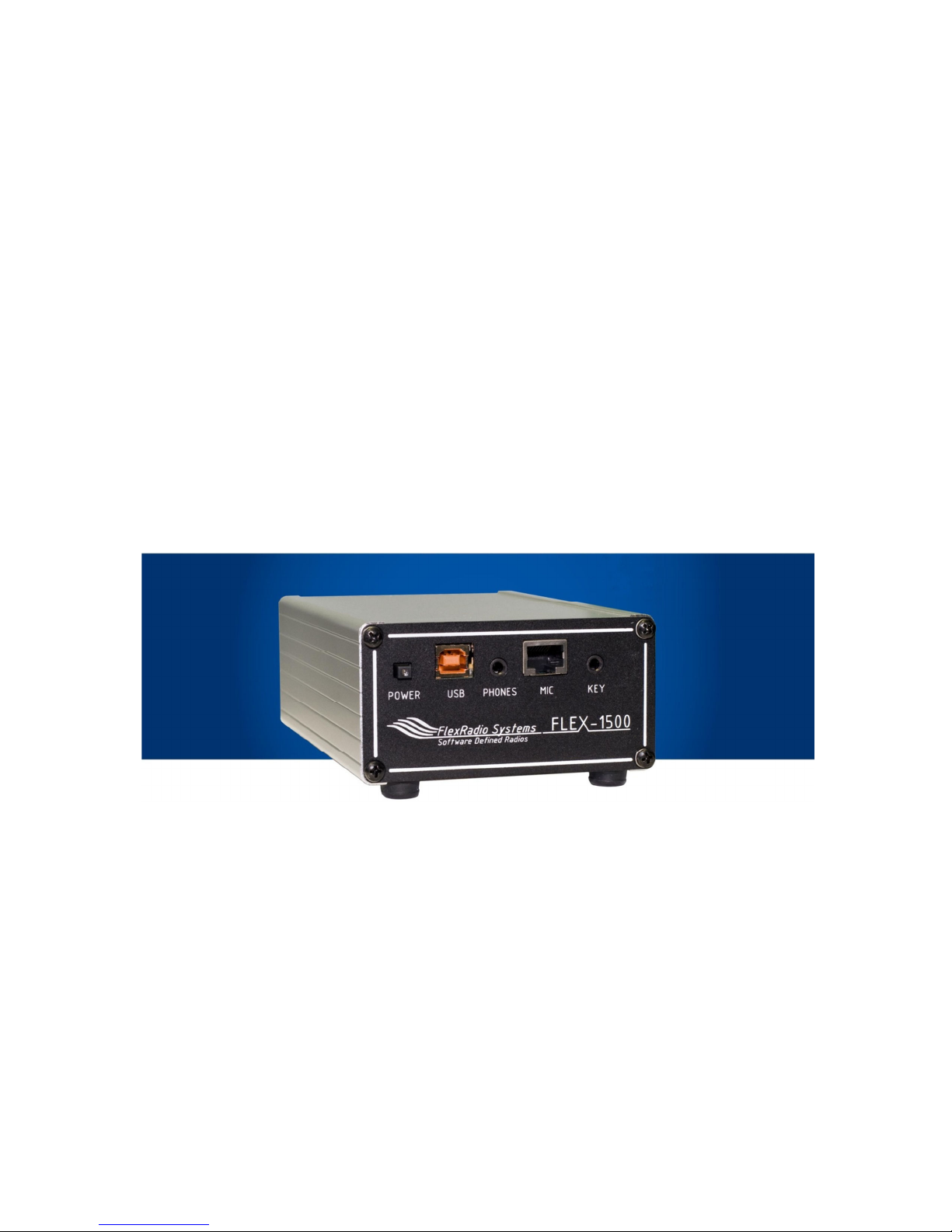
Front View - FLEX-1500

Revision 1.0
4
Copyright FlexRadio Systems, 2010-2011
Theory of Operation
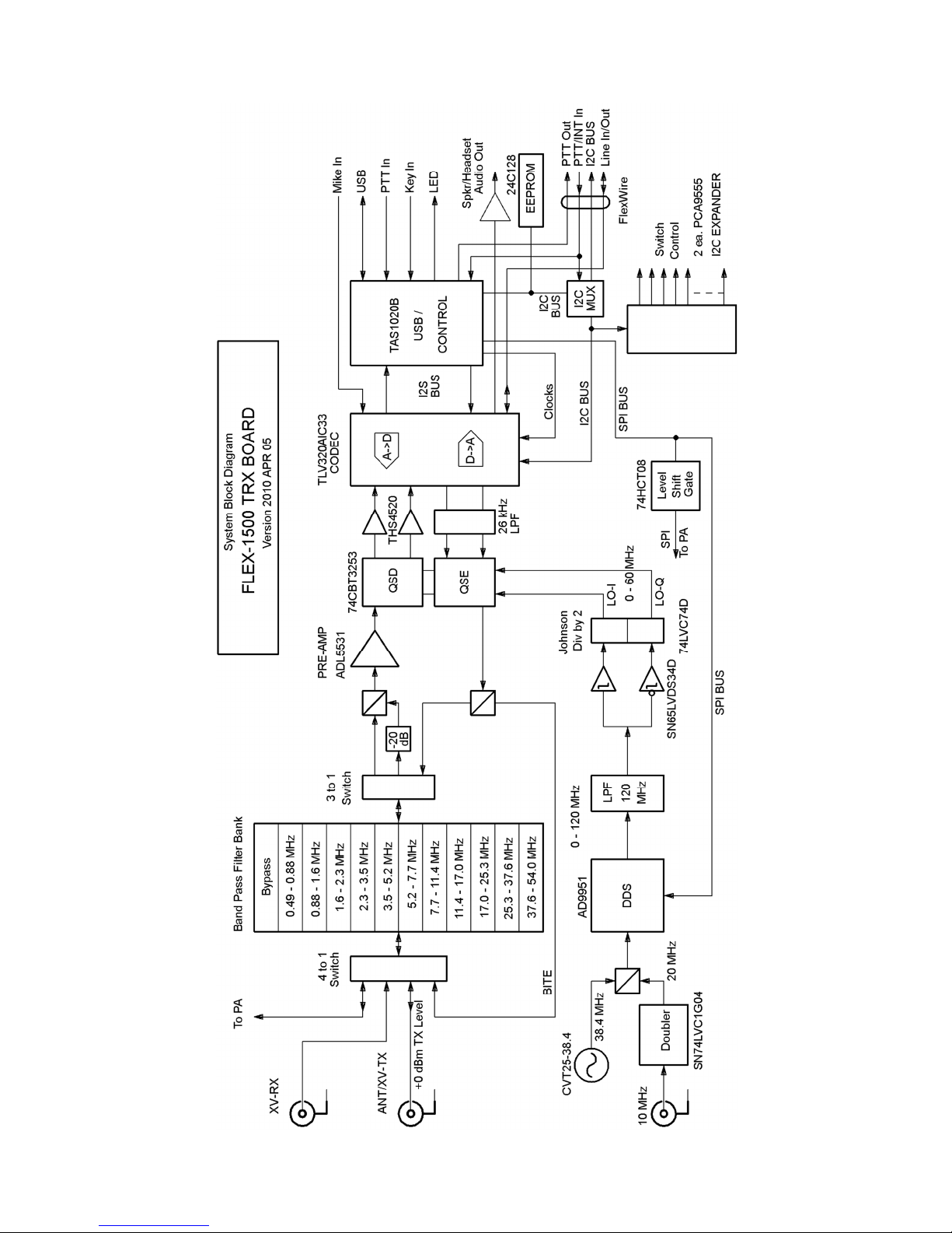
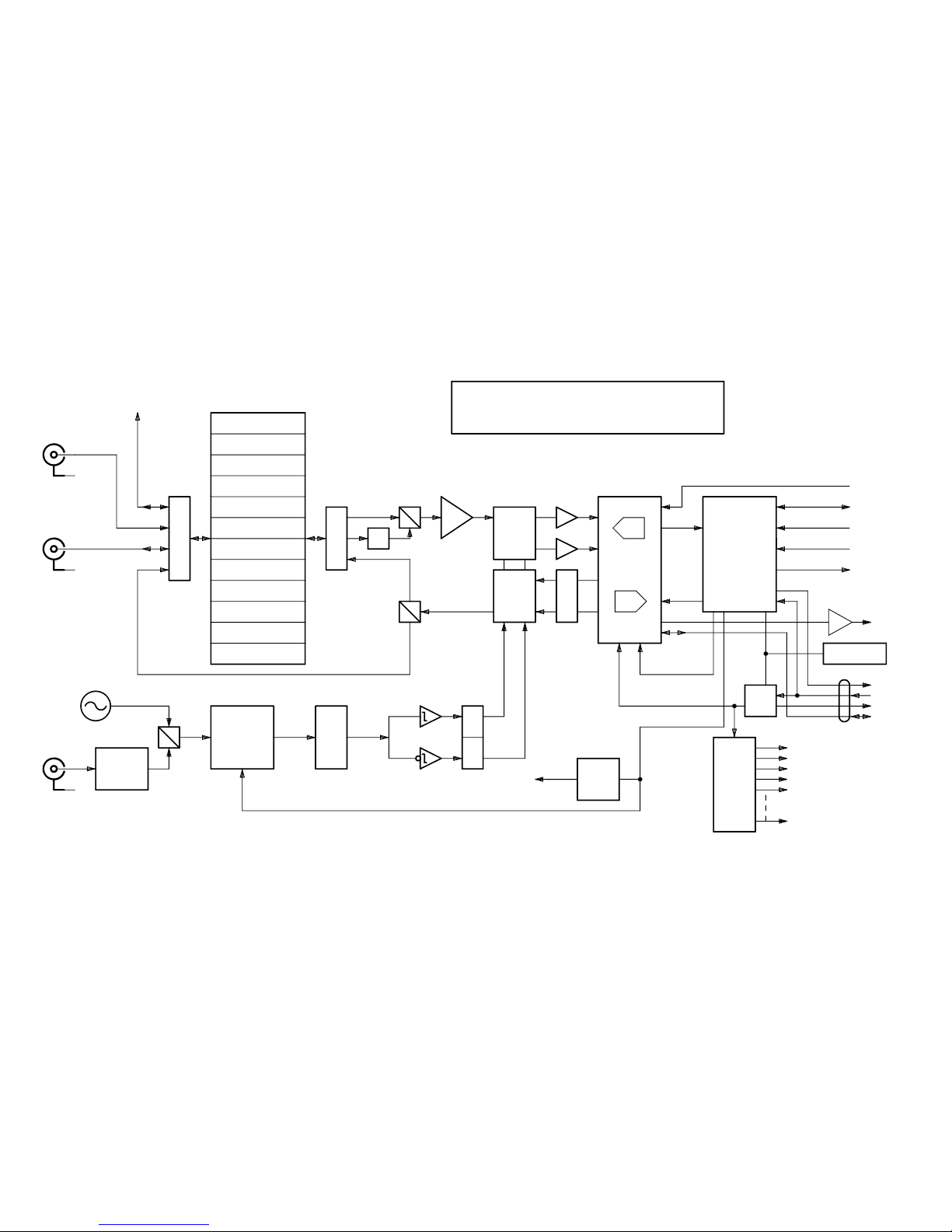
Refer to the B ock Diagrams on the two fo owing pages.
The detai ed schematic are inc uded in Appendix “A” and Appendix “B”.
The unit is powered by +13.8 Vo ts DC, supp ied via the 2.5 mm x 5.5 mm coaxia power
connector on the rear of the unit. The unit has an interna 3.0 Ampere fuse that wi b ow
if the unit draws excessive current or if the po arity of the power connected to the unit is
reversed.
The FLEX-1500 CPU (TAS1020B Streaming USB Contro er) wi communicate via
USB for both contro and streaming baseband data with the host CPU running the
PowerSDR software. The CPU in the FLEX-1500 has contro of a switching, signa
routing, frequency generation via the DDS, F exWire port, audio amp ifier, as we as
audio and baseband routing, CODEC c ock generation, data conversion, gain and eve
contro s for the radio.
Communication between the F ex-1500 radio and the host computer is via a USB
connection capab e of USB 1.1 or higher eve USB operation. The protoco is USB
“Fu Speed” or 12 Megabits per second data transfer rate.
Power Systems and Distribution
The transceiver board requires a source of regu ated +5 Vo ts at approximate y 400 mA
to function. +3.3 Vo ts is supp ied to the board in genera by a inear +3.3Vo t regu ator
derived from the +5 Vo t ine. Additiona +3.3 Vo t and +1.8 Vo ts required to operate
some of the integrated circuits is provided by point-of- oad regu ators in the vicinity of
the IC.
Overa power for the unit is derived from the +13.8 Vo t input on the RFPA board.
This 13.8 Vo ts direct y supp ies the re ays and power amp ifier transistors. It is a so
feeds two regu ators. A 6 Vo t regu ator is switched on when transmitting, and off when
receiving. This switched +6 Vo t output is used to bias the RF power transistors. A
separate +5 Vo t regu ator supp ies power for the SPI decoder and re ay driver IC on the
RFPA board, as we as supp ies a +5 Vo t power to the transceiver board (PTRX) via
the board to board interconnect system.
Revision 1.0
5
Copyright FlexRadio Systems, 2010-2011

Revision 1.0
6
Copyright FlexRadio Systems, 2010-2011

Revision 1.0
7
Copyright FlexRadio Systems, 2010-2011
ontrol Busses
There are severa contro busses that interconnect the radio. A USB “Fu Speed” bus
interconnects the host computer running PowerSDR with the on-board CPU, the
TAS1020B. Contro from the TAS1020B CPU to the rest of the radio and externa
contro is via an I2C bus system, and two SPI busses.
Firmware for the CPU is resident in a oca (I2C) EEPROM on the transceiver board.
Upon power up, the CPU wi ook for the presence of a proper y programmed EEPROM,
oad this code, begin execution, and register with the host computer as a FLEX-1500
device. In the absence of the EEPROM, or ack of correct y identified firmware, the CPU
wi execute from interna ROM, and identify itse f to the host computer as a “TI DFU
device.”
The FLEX-1500 CPU wi communicate via USB for both contro and streaming
baseband data with the host CPU running the PowerSDR software. The CPU in the
FLEX-1500 has contro of a switching, signa routing, frequency generation via the
DDS, F exWire port, audio amp ifier, as we as audio and baseband routing, CODEC
c ock generation, data conversion, gain and eve contro s for the radio. A of the above
must be trans ated from oca hardware and register contro s to the Command and Data
structures chosen for USB transport and interface in the host to the PowerSDR software.
I2C Bus
The I2C bus exists as three instances.
(1.) The computer bus (I2C-C), which contains the (master) CPU, the EEPROM
containing program memory and ca ibration parameters, and the Bus Mux.
(2.) The Interna I2C bus, (I2C-I) containing the two bus expanders and the
CODEC chip.
(3.) The Externa I2C bus (I2C-E) which is routed to the F exWire DB-9
connector, and is on y used in conjunction with an externa F exWire device.
The I2C Bus Mux se ects whether the Computer I2C bus wi be connected to the Interna
or Externa I2C bus extension at any given time, as we as passing any interrupt requests
upwards to the CPU. Since the EEPROM and the Bus Mux are on the computer bus, their
addresses wi appear in a I2C bus spaces.
I2C Bus Structure
The I2C bus address va ues are provided according to the TI convention, where the
address is an eight bit word, expressed as two hexadecima characters. The east

Revision 1.0
8
Copyright FlexRadio Systems, 2010-2011
significant bit is actua y the ~read/write bit, but is a ways presented as a “0” when the
address is expressed. The TAS1020B is the I2C Bus Master and is a ways connected to
the I2C Mu tip ex Chip and the EEPROM.
When the Bus Mux is set to “Outside,” the I2C bus is routed to the appropriate pins on
the F exWire connector. When set to “Inside” the I2C bus is routed to the CODEC, and
the two Bus Expanders, which convert I2C commands to many high/ ow outputs used to
contro the individua switches that contro signa routing in the radio.
The Audio Amp ifier is contro ed by genera purpose outputs from the CODEC.
SPI Bus
There is a so a SPI bus, used to contro the DDS and the RFPA. It appears as two
physica instances, a 3.3V version and a 5V version. The SPI is outbound contro on y,
for both the AD9951 DDS and RF PA board.
The AD9951 DDS is contro ed via the 3.3 Vo t SPI bus, direct y from the CPU.
The DDS can be programmed to operate with either a 20 MHz or 38.4 MHz reference
input. The 20 MHz signa comes from doub ing the externa 10 MHz input, and the 38.4
MHz is generated by an onboard temperature compensated crysta osci ator.
The TPIC6B595 Re ay Driver is contro ed by the 5 Vo t SPI bus, and contro s the
fo owing re ays according to the band of operation or transmit/receive status.
A “High” SPI contro bit is the active state, which provides a LOW output from the re ay
driver to turn the re ays ON.
I.C. Name
Bit
Pin
Name
Function
Initial
Drain0 0 4 15M Active = 17 or 15 Meter Band 0 = Inactive
Drain1 1 5 160M Active = 160 Meter Band 0 = Inactive
Drain2 2 6 20M Active = 30 or 20 Meter Band 0 = Inactive
Drain3 3 7 6M Active = 6 Meter Band 0 = Inactive
Drain4 4 14 80M Active = 80 Meter Band 0 = Inactive
Drain5 5 15 10M Active = 12 or 10 Meter Band 0 = Inactive
Drain6 6 16 XMIT HIGH = Trans it ode, LOW = Receive ode 0 = Receive
Drain7 7 17 40M Active = 60 or 40 Meter Band 0 = Inactive
RF Signal Processing
The incoming RF signa s may be received via the antenna connector on the RFPA board,
the transverter receive connector, or the transverter common connector. These signa s are
routed via the appropriate bandpass fi ter, then either direct y to the preamp, or through a

Revision 1.0
9
Copyright FlexRadio Systems, 2010-2011
20 dB pad to offset the gain of the preamp. The output of the preamp is fed to the QSD
down-mixer, with an output of I and Q baseband signa s in the range of 0 to 24 kHz.
The QSD down-mixer is a so supp ied with a quadrature oca osci ator signa which is
derived from the DDS. The DDS operates at twice the desired oca osci ator signa ,
passes though a 120 MHz ow pass fi ter, into a Johnson Counter that both divides the
DDS frequency by two, as we as generates the two quadrature oca osci ator signa s.
In transmit, in a reverse manner, I-Q baseband signa s from the CODEC in the baseband
range of 0 to 24 kHz are supp ied to the QSE, a ong with the quadrature oca osci ator
signa s at the operating frequency, resu ting in a direct QSE output on the fina transmit
frequency, which is routed via the bandpass fi ters to either the transverter output
connector, or the input to the RFPA.
Baseband Processing
In the receive direction, output I and Q signa s from the QSD are passed through a set of
OpAmps that have 18 dB of signa gain and 28 kHz ow pass fi ters, then sent to the
CODEC for digitization and transmission to the host computer.
In transmit, ana og I and Q signa s output from the CODEC are fi tered in a 26 kHz ow
pass fi ter to remove wideband digita noise, then sent to the QSE for up-mixing.
ommunications
In the receive configuration, digitized I and Q signa s from the CODEC, representing the
received pass band, are transferred using the I2S protoco to the Streaming USB
contro er. This contro er then transfers this information via the USB protoco to the
host computer. Processed and demodu ated audio is returned via the USB protoco to the
contro er, then transferred to the CODEC via I2S protoco for conversion into ana og
audio signa s.
In transmit configuration, digitized microphone audio signa s from the CODEC are
transferred using the I2S protoco to the Streaming USB contro er. This contro er then
transfers this information via the USB protoco to the host computer. Processed transmit
audio in a digita I and Q format is returned via the USB protoco to the contro er, then
transferred to the CODEC via I2S protoco for conversion into ana og baseband signa s to
drive the QSE up-mixer.
In the BITE (Bui t In Test Equipment) configuration, digitized I and Q signa s from the
CODEC, representing the received pass band, are transferred using the I2S protoco to
the Streaming USB contro er. This contro er then transfers this information via the
USB protoco to the host computer. Transmit test signa s in a digita I and Q format are

Revision 1.0
10
Copyright FlexRadio Systems, 2010-2011
sent via the USB protoco to the contro er, then transferred to the CODEC via I2S
protoco for conversion into ana og baseband signa s to drive the QSE up-mixer.
Audio Amplifier
An audio amp ifier is present, capab e of driving stereo headphones, or stereo powered
speakers, in the Stereo configuration, or a monophonic speaker direct y, in the Mono
configuration. In stereo, each of the two amp ifiers are carrying the appropriate eft or
right channe information, and driving a ow power amp ifier suitab e for headphones or
high impedance oads. In the Mono configuration, the two incoming stereo signa s are
mixed together to form a sing e mono signa . This is fed to one amp ifier direct y and
inverted and fed to the other amp ifier to form an “H-Bridge” speaker amp ifier. In this
mode the speaker must be wired to bridge the amp ifier output (connect to tip and ring on
stereo speaker p ug) with no connection to ground.

Revision 1.0
11
Copyright FlexRadio Systems, 2010-2011
Alignment, Test and Calibration
The on y manua a ignment required is setting the quiescent bias for the RF power
transistors on the RFPA (PPA05 PCB.)
A other a ignment, test and ca ibration wi occur under computer contro using
production test software bui t into PowerSDR.
Bias Adjustment
FLEX-1500 RFPA (PPA05) Bias settings
==
Power Supp y Setup:
Adjust Power Supp y to 13.8 Vo ts Output Vo tage.
Adjust Power Supp y maximum current imit to 2.5 Amperes. To do this, p ace a short
across the output termina s of the power supp y and adjust the Output Current knob to
read 2.5 Amps on the current meter.
==
The Bias settings are norma y set with the PA board out of the radio. It does not have to
be connected to the TRX board, since it is a DC settings, and you do not want any RF
drive present.
With just the PA by itse f on the workbench...
P ug in +13.8 Vo ts into the norma power connector.
To turn on the PA bias, ground the test point named "XMIT" at the ower right corner of
the board, between K8 and K15. This wi a so activate re ay K15, so you wi hear a
"c ick."
To measure current in the driver transistor, there is a one Ohm shunt resistor between test
points DM- and DM+. Put a vo tmeter that wi give good readings in the range of 50
mi iVo ts across these two test points. Norma y you wou d adjust R8 for 50 mi iVo ts
p us or minus 5 mi iVo ts corresponding to 50 mi iAmps f owing through driver
transistor Q1.
(Warning: do not use ong test probes that wi go a the way through the PC board and
touch the p ate be ow. This wi short the +13.8 Vo ts to ground and/or destroy the
metering resistor R2.)

Revision 1.0
12
Copyright FlexRadio Systems, 2010-2011
After adjusting bias on Q1, adjust bias on Q3. The procedure with a co d p ate wi be to
set tota power drain to 530 mA, p us or minus 25 ma, by adjusting R10.
You wi see it drift some with temperature. With a hot base p ate, it can rise as high a
580 mA.
Test and alibration
FLEX-1500 Transceiver Fina Assemb y, Test and Ca ibration.
Note: The FLEX-1599 USB signa generator is required to test receiver image
ca ibration, and operation of the 10 MHz externa reference. A other tests may be run
without the USB signa generator. If not detected by the host computer, the appropriate
test buttons wi be disab ed and “grayed out.”
Note: The PowerMaster mode PM003 is required to run power ca ibration of the
transmitter. If not detected by the host computer, the appropriate test button wi be
disab ed and “grayed out.”
Required test equipment:
Host computer with PowerSDR version 2.0 or ater with appropriate drivers for the
FLEX-1500, FLEX-1599 signa generator, and PowerMaster RF power meter
insta ed.
USB Signa Generator, F exRadio Systems mode FLEX-1599.
PowerMaster RF Power Meter mode PM003 with seria interface, or USB seria adaptor
as appropriate to connect to the host computer.
Loop-back test cab e per accompanying diagram.
Suitab e power and RF BNC connection cab es.
Power Supp y capab e of supp ying at east 2.5 Amperes at 13.8 Vo ts with maximum
current imit adjustab e to 2.5 Amperes.
==
Power Supp y Setup:
Adjust Power Supp y to 13.8 Vo ts Output Vo tage.
Adjust Power Supp y maximum current imit to 2.5 Amperes. To do this, p ace a short
across the output termina s of the power supp y and adjust the Output Current knob to
read 2.5 Amps on the current meter.
==

Revision 1.0
13
Copyright FlexRadio Systems, 2010-2011
If there is any question as to whether the quiescent bias currents are proper y set on the
RFPA power transistors, they shou d be set prior to performing the PA ca ibration tests.
==
P ug the BNC-Coaxia cab e from the PowerMaster Watt meter into the BNC connector
on the RFPA.
P ug the USB cab e from the computer into the USB connector on the front edge of the
PTRX board.
P ug the oop-back test cab e into the F exWire DB-9 connector on the rear card edge,
and the Key and Mike connectors into the connectors on the front card edge.
P ug the +13.8 Vo t power connector into the power connector on the RFPA.
==
Turn on the power switch on the PTRX board. The B ue LED shou d ight within two
seconds.
Open PowerSDR 2.0
Press "Start"
Note that the program is running and a moving Panadaptor noise f oor appears.
Bring up the production test screen by pressing Contro -Shift-P.
Check that the appropriate Com Port for the PowerMaster RF Power Meter is indicated.
The fu y automated sequence of tests may be started by pressing the “Test A ” at the
bottom of the test screen, or the individua tests may be runfor diagnostic purposes, by
pressing their individua buttons.
If a tests are passed, as indicated by a green buttons, then radio eve testing of the
assemb ed radio is comp ete.
C ose Production Test window, stop PowerSDR, c ose PowerSDR, turn off power switch
on PTRX and remove cab es from Radio Assemb y.
==

Revision 1.0
14
Copyright FlexRadio Systems, 2010-2011
Troubleshooting and Diagnostics
For bench testing the comp ete unit or RFPA as a stand a one board, it is recommended
that a 13.8 Vo t current imited bench supp y is used, with the current imiter set to 2.5
Amperes.
If necessary to test a transceiver board as a stand a one board, a ho ding fixture with
number 4 corner pins can be used to ho d the board. A source of regu ated +5.0 Vo ts,
current imited at 600 mA may be app ied in p ace of the power source jumper on J6, if
present, or P2.
The resu ts from the factory tests bui t into PowerSDR shou d provide direction as to any
fai ures in the radio. The keyboard command to invoke the factory test page in
PowerSDR is Contro -Shift-P.
The b ue ight in the center of the power-on switch is contro ed by the CPU. This ight
wi on y ight if the CPU has down oaded va id firmware from the EEPROM and has
comp eted initia ization.
If no b ue ight, check a vo tages, inc uding the output of the dedicated +3.3V regu ator
feeding the CPU digita power pins, which is separate from the genera 3.3V regu ator.
If the b ue ight is present, but the unit wi not enumerate on the USB host, check cab es,
connectors, and proper vo tage output from the dedicated +3.3V regu ator (IC28) feeding
the CPU digita power pins.
None of the band pass fi ters in the transceiver board shou d have an insertion oss greater
than 6 dB inside the band pass, so signa tracing with an RF signa generator and eve
meter or spectrum ana yzer is very practica .
Excessive fi ter oss is usua y associated with an incorrect inductance va ue, or shorted
turns in one or more fi ter inductors.

Revision 1.0
15
Copyright FlexRadio Systems, 2010-2011
Assembly and Disassembly
Required tools
Number 1 Phi ips and number 2 Phi ips screwdrivers are needed, and a 3/16 inch nut
driver to remove the DB-9 retention nuts.
Disassembly
Remove the two retention nuts on either side of the F exWire DB-9 connector.
Remove the four corner screws on both the front and back covers using the number 2
Phi ips screwdriver.
Observe the position of the upper PCB. It is in the fourth card s ot. That is, three empty
s ots are above it. Observe the position of the two screw c earance ho es on the bottom of
the case. These ho es are not equa y spaced from the ends. The ho e farthest from the
edge is on the rear end (end with a BNCs.)
Remove the four bottom feet using the number 1 Phi ips screwdriver.
Gent y s ide both cards toward the rear pane , the one with a the BNCs unti the
connected pair of cards are c ear of the outer case. The two cards may be separated.
Re-assembly
Reconnect the cards with the ten pin card to card connector.
Orient the case so that the rear of the case (end with screw c earance ho e spaced farthest
from the edge) is upwards.
Lower the upper board into the fourth board s ot from the top of the housing. Once the
upper board engages the side rai s by an inch or two, ower the ower board and heat
spreader p ate into the box and engage the board to board to board connection. The ower
(PA board) shou d not engage any board s ots and wi just rough y center in the bottom
of the case. Gent y s ide in the pair of cards unti fu y inside the new case.
Check that the two transistor mounting screws in the heat spreader are visib e and
rough y centered in the screw c earance re ief ho es in the bottom of the case.
Insta the four feet using the number 1 Phi ips screwdriver.

Revision 1.0
16
Copyright FlexRadio Systems, 2010-2011
Insta the front and rear pane s, using the b ack #6 pan head screws, with a number # 6
f at washer under each screw head, with the number 2 Phi ips screwdriver.
Insta the two retention screws, with f at washer and ock washer on either side of the
DB-9 connector.
Fuse Replacement
The F ex-1500 contains a 3 Ampere, standard automotive type AutoFuse Mini fuse to
protect the radio in the event of an interna short, excessive power drain, or app ication of
power with reversed po arity to the radio. Rep ace with Litt eFuse #297003 or
equiva ent, housing co or purp e, 3 Ampere.
To rep ace the fuse, fo ow the “Disassemb y: instructions above, and separate the two
boards.
The fuse, component designator F1, is ocated on the RF Power Amp ifier board
immediate y behind the +13.8 Vo t power connector,. The fuse is a b ade type fuse and is
removed by pu ing the fuse away from the board. It is rep aced by inserting the contact
b ades into the fuse ho der, and pushing downwards towards the PC board.
Reassemb e the radio by fo owing the “Re-assemb y” instructions above.

Revision 1.0 Copyright FlexRadio Systems, 2010-2011
Appendix "A"
Schematic, PTRX (Transceiver) Board
10 MHz
SPI BUS
FLEX-1500 TRX BOARD
XV-RX
ANT/XV-TX
To PA Band Pass Filter Bank
Bypass
1.6 - 2.3 MHz
5.2 - 7.7 MHz
7.7 - 11.4 MHz
11.4 - 17.0 MHz
25.3 - 37.6 MHz
37.6 - 54.0 MHz
LPF
MHz
AD9951
DDS
Johnson
Div by 2
LO-I
LO-Q
0 - 120 MHz
38.4 MHz
Doubler 20 MHz
Mike In
USB
Audio Out
CODEC
USB /
QSE
QSD
0 - 60 MHz
BITE
I2C BUS
Switch
Control
I2C EXPANDER
A->D
D->A
120 SPI BUS
Key In
Clocks
TLV320AIC33
TAS1020B
74LVC74D
SN65LVDS34D
2 ea. PCA9555
CVT25-38.4
SN74LVC1G04
THS4520
0.88 - 1.6 MHz
0.49 - 0.88 MHz
PTT In
LED
Version 2010 APR 05
ADL5531
4 to 1
Switch
+0 dBm TX Level
To PA
17.0 - 25.3 MHz
3.5 - 5.2 MHz
2.3 - 3.5 MHz
Level
Shift
Gate
74HCT08
26 kHz
LPF EEPROM
FlexWire
74CBT3253
I2C
MUX I2C BUS
System Block Diagram
Spkr/Headset
SPI
24C128
CONTROL
PTT/INT In
PTT Out
Line In/Out
I2S
I2C
BUS
PRE-AMP
BUS
-20
dB
3 to 1
Switch

GND
5.1k
GND
GND
.1u.1u
SD-73100
SD-73100
GND
5.1k
GND
GBLC03C
GBLC03C
GND
TC4-1T
GND
GND
.1u
GND
GND
10k
.1u
.1u
.1u +3.3V
10n 10n
GND
GND
GND
SSQ-105-01-F-D +12V
.1u
GND
+3.3V
619
3.32k
.1u
619
619
3.32k 3.32k
GND
BAS70-00-V-GS08
BAS70-00-V-GS08
GND
1267W
.1u
74AHC1G04DBV
1M 100
0
1M
GND
+3.3V
.1u
10k
GND
Copyright FlexRadio Systems 2009, 2010
XVRX
ANT
10MW TX/COM
FRONT END
2.) Ground
1.) SPI5-LOAD
3.) SPI5-CLK
5.) SPI5-DATA
4.) +12V
7.) +5
9.) RF
10.) Ground
8.) +5
Flat Cable Assignments
6.) Ground
R2
C4C6
J1G$1
J2G$1
R1
D1
D2
3
2
16
4
T1
C1
R7
C16
X1
C13
C15
C7 C8
RFTP1
10
8
6
4
2
P2
9
7
5
3
1
C275
13
GND
14
15
V2 3
11
V1 4
VDD 2
GND
1
GND
5
GND
7
GND
9
GND
10
GND
12
8
6
PAD
NC 16
IC1
PE42641
R3
R4
C3
R5
R6
R8 R9
D3
D4
L1
C5
24
IC2
35
IC2P
GND VCC
R10
R72
R73
R87
C206
R95
SPI5-CLK/8
BITE/5
FRTENDA/11
FRTENDB/11
20MHZ/9
5V-PA/12
BPFI/2
SPI5-LOAD/8
SPI5-DATA/8
RF1
RF2
RF3
RF4
ANT
RFC
10 MHz Input
10 MHz Doubler

MaxiSpring
MaxiSpring
BAND 1
BAND 2
BAND 3
BAND 4
Delevan
Coilcraft CS1812
GND
GND
+3.3V
+3.3V
307n 307n 307n 307n
91p 130p 91p
51p 82p 82p 51p
GND GND GND
491n 491n 491n 491n
150p 200p 150p
75p 110p 110p 75p
GND GND GND
680n 680n 680n 680n
110p 180p 180p 110p
220p 300p 220p
GND GND GND
1.2u_CS 1.2u_CS 1.2u_CS 1.2u_CS
150p 220p 220p 150p
300p 390p 300p
GND GND GND
+3.3V
+3.3V
10n10n10n10n
10n10n10n10n
GND
GND
+3.3V
+3.3V
+3.3V
.1u
GND
.1u
.1u
GND
.1u
.1u
GND
.1u
.1u
GND
.1u
BANDPASS FILTER BANK - HIGH
11.4 - 17.0 MHz
37.6 - 56 MHz
25.3 - 37.6 MHz
17.0 - 25.3 MHz
Physical Position on PCB:
Band 4 - 11.4 - 17.0 MHz
Band 8 - 2.3 - 3.5 MHz
Band 2 - 25.3 - 37.6 MHz
Band 5 - 7.7 - 11.4 MHz
Band 9 - 1.6 - 2.3 MHz
Band 1 - 37.6 - 56.0 MHz
Band 12 - Bypass
Band 6 - 5.2 - 7.7 MHz
Band 10 - 0.88 - 1.6 MHz
Band 3 - 17.0 - 25.3 MHz
Band 7 - 3.5 - 5.2 MHz
Band 11 - 0.49 - 0.88 MHz
Copyright FlexRadio Systems 2009, 2010
51
3
6
4
2
CTRL
VDD
RFC RF1
RF2
GND
K5
PE4259
5
1
3
6
4
2
CTRL
VDD RFC
RF1
RF2 GND
K6
PE4259
51
3
6
4
2
CTRL
VDD
RFC RF1
RF2
GND
K7
PE4259
5
1
3
6
4
2
CTRL
VDD RFC
RF1
RF2 GND
K8
PE4259
L2 L3 L4 L5
C25 C26 C27
C21 C22 C23 C24
L6 L7 L8 L9
C40 C41 C42
C36 C37 C38 C39
L10 L11 L12 L13
C49 C50 C51 C52
C53 C54 C55
L14 L15 L16 L17
C58 C59 C60 C61
C62 C63 C64
C33C48C57C66
C31C46C56C65
51
3
6
4
2
CTRL
VDD
RFC RF1
RF2
GND
K1
PE4259
5
1
3
6
4
2
CTRL
VDD RFC
RF1
RF2 GND
K2
PE4259
51
3
6
4
2
CTRL
VDD
RFC RF1
RF2
GND
K3
PE4259
5
1
3
6
4
2
CTRL
VDD RFC
RF1
RF2 GND
K4
PE4259
C245
C265
C272
C273
C277
C278
C279
C280
BPFI/1
BPFO/3
BAND04/11
BAND03/11
BAND01/11
BAND02/11
Other manuals for FLEX-1500
2
Table of contents
Other FlexRadio Systems Radio manuals


Popular Radio manuals by other brands

ML SOLUTION
ML SOLUTION FUN BR 24 operating instructions

Hama
Hama 00054820 operating instructions

HDigit
HDigit FM / Internet Radio instruction manual

Morphy Richards
Morphy Richards IB27015 operating instructions

Tivoli Audio
Tivoli Audio PORTABLE AUDIO LABORATORY PLUS BT owner's manual

Sangean
Sangean WFR-1 - DATASHEET 3 datasheet


