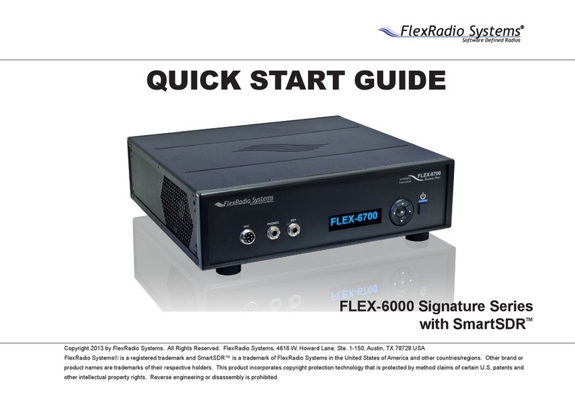
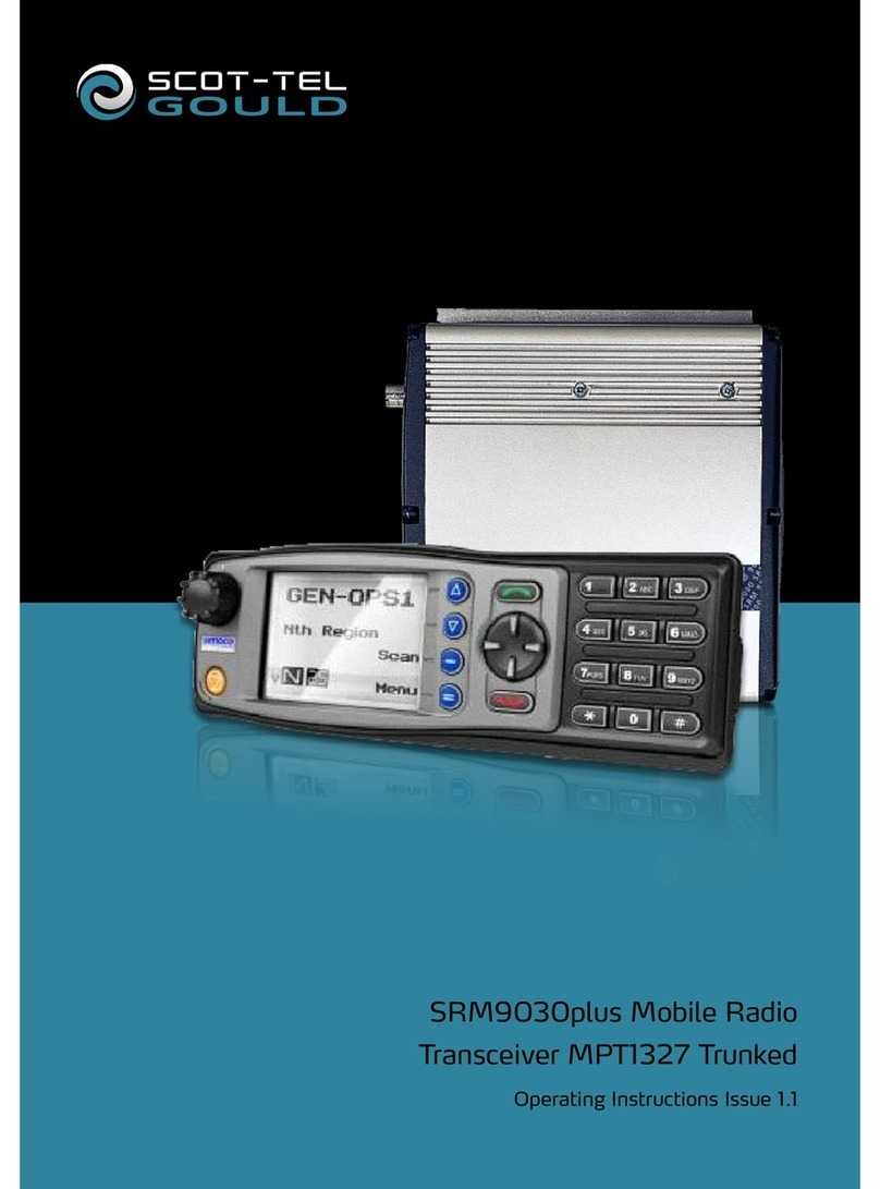
FlexRadio Systems FLEX-6500 Quick user guide

Copyright 2015 FlexRadio Systems. All Rights Reserved. FlexRadio Systems is a registered trademark and SmartSDR is a
trademark of FlexRadio Systems. All other brands or names are trademarks of their respective owners.
FLEX-6000 SIGNATURE SERIES
FLEX-6000 HARDWARE REFERENCE MANUAL
Version 1.6.21
2/08/2016

FLEX-6000 Signature Series –FLEX-6000 Hardware Reference Manual
Page 2 of 48
Copyright 2016 FlexRadio Systems. All Rights Reserved.
VERSION HISTORY
Version
#
Implemented
By
Revision
Date
Approved
By
Approval
Date
Reason
1.0.0
Greg Jurrens
9/30/2013
Lori Hicks
9/30/2013
Original Draft
1.0.1
Greg Jurrens
10/1/2013
Tim Ellison
10/1/2013
Minor Edits –Name
change
1.0.5
Greg Jurrens
12/3/2013
Revised sec. 6.2 & 7.4
for clarity. Added sec. 11
(GPSDO)
1.1.3
Lori Hicks
2/17/2014
Greg
Jurrens
2/18/2014
Moved to SVN Doc.
Control Process. Added
Voltage levels. Minor
Edits
1.2.0
Matt
Youngblood
5/8/2014
Added FLEX-6300
1.2.1
Tim Ellison
6/3/2014
Various formatting edits.
Added 6300 specs
1.2.17
Matt
Youngblood
7/1/2014
Updated Power Button
Description
1.3.0
Tim Ellison
8/15/2014
Various minor edits and
editions.
1.4.0
Tim Ellison
1/30/2014
Added section on FHM-1
Added ATU section
Various minor edits
1.4.0
Lori Hicks / Ken
Simmons
2/4/2015
Added information for the
FLEX-6700R
1.4.0
Tim Ellison
3/16/2015
Miscellaneous minor
edits. Added section on
Calibration
1.4.11
Tim Ellison
5/11/2015
Miscellaneous minor
edits and corrections
1.4.16
Tim Ellison
6/30/2015
Miscellaneous minor
edits
1.5.0
Tim Ellison
9/14/2015
Miscellaneous edits and
minor corrections
1.5.1
Tim Ellison
10/6/2015
Miscellaneous edits and
minor corrections
1.6.17
Tim Ellison
1/11/2016
Miscellaneous edits and
minor corrections
1.6.21
Tim Ellison
2/08/2016
Miscellaneous edits and
minor corrections

FLEX-6000 Signature Series –FLEX-6000 Hardware Reference Manual
Page 3 of 48
Copyright 2016 FlexRadio Systems. All Rights Reserved.
TABLE OF CONTENTS
1INTRODUCTION.................................................................................................................... 7
1.1 Welcome................................................................................................................... 7
1.2 Manual Layout.......................................................................................................... 7
1.3 Notices to the User................................................................................................... 8
2WARRANTY INFORMATION............................................................................................. 9
3IMPORTANT NOTICE –READ BEFORE OPERATING THIS UNIT ........................ 10
3.1 Precautions............................................................................................................. 10
3.2 Legal Notices .......................................................................................................... 11
3.3 Copyright Information........................................................................................... 13
4SPECIFICATIONS................................................................................................................ 14
4.1 General.................................................................................................................... 14
4.2 Transmitter ............................................................................................................ 15
4.3 Receiver.................................................................................................................. 15
5UNPACKING AND INSPECTATION................................................................................ 16
5.1 Unboxing................................................................................................................. 16
5.2 Visual Inspection.................................................................................................... 16
5.2.1 General .............................................................................................................. 16
5.2.2 Radio.................................................................................................................. 16
5.2.3 Included Accessories........................................................................................ 16
5.2.4 Additional Items not Included but Required ................................................. 17
5.3 Reporting Damage ................................................................................................. 17
6FRONT PANEL CONTROLS AND CONNECTIONS ..................................................... 18
6.1 Microphone Jack .................................................................................................... 19
6.1.1 Connector Pinout.............................................................................................. 19
6.1.2 Supported Microphone Types......................................................................... 19
6.2 Headphone Jack ..................................................................................................... 19
6.3 CW Key/Paddle Jack.............................................................................................. 19
6.4 Multi-Function Display.......................................................................................... 20
6.5 Navigation Keys ..................................................................................................... 20
6.6 Multi-Function Indicator LED............................................................................... 20
6.6.1 Chart for Indicator Color Codes ...................................................................... 20
6.6.2 Chart for Indicator Color Codes with optional GPSDO Installed.................. 20
6.7 Power Switch ......................................................................................................... 21
6.7.1 “Soft Power Control” Multiple Operations ..................................................... 21

FLEX-6000 Signature Series –FLEX-6000 Hardware Reference Manual
Page 4 of 48
Copyright 2016 FlexRadio Systems. All Rights Reserved.
7REAR PANEL CONNECTIONS......................................................................................... 22
7.1 DC Power Input...................................................................................................... 23
7.1.1 Power Pole 30 Amp.......................................................................................... 24
7.1.2 Fused Internally at 30 Amps ........................................................................... 24
7.2 USB 2.0 Ports.......................................................................................................... 24
7.3 Powered Speakers ................................................................................................. 24
7.4 Accessory Connector ............................................................................................. 25
7.4.1 Pin 1: Line In..................................................................................................... 25
7.4.2 Pin 2: Line1 Out ................................................................................................ 25
7.4.3 Pin 3: Line2 Out ................................................................................................ 25
7.4.4 Pin 4: KEY/FSK/INT In .................................................................................... 25
7.4.5 Pin 5, Reserved for future use (FLEX-6300 only).......................................... 25
7.4.6 Pin 5, Pin 6, Pin 7, Pin 8 and Pin 10: GROUND............................................... 25
7.4.7 Pin 9: +5VDC ..................................................................................................... 26
7.4.8 Pin 11: Accessory TX........................................................................................ 26
7.4.9 Pin 12: SDA I/O................................................................................................. 26
7.4.10 Pin 13: Accessory TX REQ................................................................................ 26
7.4.11 Pin 14: PTT in ................................................................................................... 26
7.4.12 Pin 15: SCL I/O.................................................................................................. 26
7.5 10Mhz Reference Clock Input............................................................................... 26
7.5.1 Radio Oscillator Startup................................................................................... 26
7.6 TX Relay Outputs [1,2,3] ....................................................................................... 27
7.7 Transceiver Antenna Ports [1,2] .......................................................................... 27
7.8 10MHz Reference Output (w/GPSDO option)..................................................... 27
7.9 Ethernet Connector ............................................................................................... 28
7.10 Balanced Audio Input ............................................................................................ 28
7.10.1 Balanced Audio Input Connectors .................................................................. 28
7.10.2 MIC vs. LINE Use............................................................................................... 29
7.10.3 Line Level.......................................................................................................... 29
7.11 GPS Antenna Input (w/GPSDO option)................................................................ 29
7.12 Remote Power On Input........................................................................................ 29
7.13 External Amplifier ALC Input ............................................................................... 29
7.14 TX Request Input (interlock)................................................................................ 29
7.15 PTT Input................................................................................................................ 30
7.16 Transverter Port .................................................................................................... 30
7.17 RX ANT-A RF Input ................................................................................................ 30
7.18 RX ANT-A RF Output.............................................................................................. 30
7.19 RX ANT-B RF Input (FLEX-6700/6700R only).................................................... 30

FLEX-6000 Signature Series –FLEX-6000 Hardware Reference Manual
Page 5 of 48
Copyright 2016 FlexRadio Systems. All Rights Reserved.
7.20 RX ANT-B RF Output (FLEX-6700/6700R only)................................................. 30
7.21 Chassis Ground ...................................................................................................... 31
7.22 AC Power Input ..................................................................................................... 31
7.23 Outputs [1, 2, 3]....................................................................................................... 31
7.24 No Connection (NC) ............................................................................................... 31
7.25 Digital Inputs [1, 2] ................................................................................................. 31
7.26 Antenna Inputs [1, 2]............................................................................................... 31
7.27 Attention Label........................................................................................................ 31
8INSTALLATION................................................................................................................... 32
8.1 Safety ...................................................................................................................... 32
8.2 Radio Placement .................................................................................................... 32
8.3 Environmental Considerations............................................................................. 32
8.4 Connecting to a PC ................................................................................................. 32
8.4.1 Ethernet Cabling Requirements...................................................................... 32
8.4.2 Direct PC Connection (Link-Local) ................................................................. 33
8.4.3 Connecting via a Local Network...................................................................... 33
8.4.4 Installing SmartSDR ......................................................................................... 34
9FHM-1 MICROPHONE........................................................................................................ 35
9.1 Specifications .......................................................................................................... 35
9.2 Tone Switch............................................................................................................. 35
9.3 Best Practices .......................................................................................................... 35
10 TRANSVERTER SETUP...................................................................................................... 36
10.1 Transmit Power Considerations .............................................................................. 37
10.2 RF Connections - Common IF ................................................................................ 37
10.3 RF Connections - Split IF........................................................................................ 37
10.4 PTT Connections..................................................................................................... 38
10.5 Sequencers............................................................................................................... 38
10.6 Multiple Transverters.............................................................................................. 38
11 DIGITAL MODE SETUP (SOUND CARD INTERFACE).............................................. 39
12 ANTENNA CONSIDERATIONS ........................................................................................ 40
12.1 Antenna Selection.................................................................................................. 41
13 ANTENNA TUNER UNIT (ATU)........................................................................................ 42
13.1 Specifications .......................................................................................................... 42
14 OPTIONAL GPS DISCIPLINED OSCILLATOR (GPSDO) SETUP ............................. 43
14.1 GPSDO Introduction .............................................................................................. 43
14.2 GPS Antenna Placement ........................................................................................ 43

FLEX-6000 Signature Series –FLEX-6000 Hardware Reference Manual
Page 6 of 48
Copyright 2016 FlexRadio Systems. All Rights Reserved.
14.3 GPSDO Lock Sequence and Status Indicators...................................................... 44
15 CALIBRATION..................................................................................................................... 45
15.1 Frequency Calibration............................................................................................. 45
16 KEY CONTACTS.................................................................................................................. 46
16.1 Headquarters / USA ................................................................................................ 46
16.2 Europe ..................................................................................................................... 46
17 REGULATORY REQUIREMENTS................................................................................... 47
17.1 European Conformity (CE)..................................................................................... 47

FLEX-6000 Signature Series –FLEX-6000 Hardware Reference Manual
Page 7 of 48
Copyright 2016 FlexRadio Systems. All Rights Reserved.
1INTRODUCTION
1.1 WELCOME
Thank you for purchasing the FLEX-6000 Signature Series software defined radio (SDR) from
FlexRadio Systems. The FLEX-6000 is an example of cutting edge SDR technology using
Digital Down Conversion (DDC) for exceptional performance and distortion free reception.
Direct Digital Up Conversion (DUC) eliminates analog mixing and IF amplification to
minimize spurious output and in-band intermodulation distortion to ensure ultra-clean RF
transmission.
The FLEX-6000 along with its SmartSDR software “ecosystem” represents the ultimate
operating experience for amateur radio operators.
1.2 MANUAL LAYOUT
The FLEX-6000 Hardware Reference Manual is designed as a guide for use while installing,
configuring, and integrating your FLEX-6000 into your amateur station. This manual
expands on the FLEX-6000 Quick Start Guide regarding connection details and hardware
configuration including basic connectivity information for interfacing with the more
common types of third-party hardware. It is designed for use in conjunction with the
SmartSDR Software User’s Guide. References to the FLEX-6000 Software User’s Guide will
be provided to assist you.
Throughout this manual, important references will be highlighted for your information and
safety. The following symbols and styles will be used:
! –WARNING: THIS MEANS THAT THERE IS A POTENTIAL SAFETY HAZARD IF THE RADIO
IS CONFIGURED OR OPERATED IMPROPERLY. PAY SPECIAL ATTENTION TO ALL “!”
WARNINGS.
Δ –CAUTION: This is a precautionary statement to acknowledge there is a risk to
damaging your radio or operating it in an unintended manner. Pay special attention to
the “Δ” symbol to get the most from your FLEX-6000.
I –Information: Important information will be highlighted with the “i” symbol. Read
these notes for helpful hints and details about your FLEX-6000.

FLEX-6000 Signature Series –FLEX-6000 Hardware Reference Manual
Page 8 of 48
Copyright 2016 FlexRadio Systems. All Rights Reserved.
1.3 NOTICES TO THE USER
IMPORTANT NOTICE - READ BEFORE OPERATING THIS UNIT
WARNING!
This radio has been configured to operate in your country according to your nation's
regulations. It will operate on frequencies which are not allowed for public use. You are
required to have a valid amateur radio license of an appropriate class from your
government to have the privileges to operate on amateur radio frequencies.
Except those actions which have been described in the FLEX-6000 Quick Start Guide, FLEX-
6000 Hardware Reference Manual, and SmartSDR Software User’s Guide, no other
manipulations to the radio are allowed. The unit must only be opened and/or serviced by
a qualified technician. Unauthorized repairs may damage the radio and void the
manufacturer’s warranty.
Please study the FLEX-6000 Quick Start Guide and the FLEX-6000 Hardware Reference
Manual and SmartSDR Software User’s Guide prior to operating the unit. These
documents contain important information for safe operation.
For any questions due to misunderstanding, translation errors and alike, please refer to the
FLEX-6000 Hardware Reference Manual and SmartSDR Software User’s Guide first.
Radio frequency energy (RF) from transmitters can interact with some electronic devices,
such as cardiac pacemakers and defibrillators. Please refer to the implanted pacemaker or
defibrillator manufacturer's instructions with respect to precautions to be taken in the
vicinity of an amateur radio transmitter. If any interaction or interference with a
pacemaker or implanted defibrillator is suspected, STOP transmitting immediately.

FLEX-6000 Signature Series –FLEX-6000 Hardware Reference Manual
Page 9 of 48
Copyright 2016 FlexRadio Systems. All Rights Reserved.
2WARRANTY INFORMATION
This Limited Hardware Warranty is effective as of the date of first shipment to the consumer.
Original equipment warranties and manufacturer hardware support for the FLEX-6300, FLEX-
6500 and FLEX-6700 applies only to the original purchaser and are not transferable unless a
warranty transfer agreement is purchased from FlexRadio Systems. FlexRadio Systems may elect
to transfer the hardware warranty to a third-party if the identity of the third-party is made known
at the time of purchase. A Return Merchandise Authorization (RMA) number is required before
sending in a product for service. An RMA number may be issued by FlexRadio Systems by
submitting a HelpDesk support ticket and undergoing troubleshooting procedures with a
technical support engineer. Any product returned for service that is out of warranty or has had
its warranty voided is subject to a one (1) hour diagnostic bench charge (currently $85 USD). This
charge will be applied to any work performed.
What is covered: During the first two (2) years after date of purchase, FlexRadio Systems will
replace defective parts free of charge (post-paid) for transceiver components only. Any
replacement hardware parts will be warranted for the remainder of the original warranty period
or ninety (90) calendar days from the date of installation or repair, whichever is longer. FlexRadio
Systems will also correct any failure caused by defective parts and materials. The complete unit
must be sent to FlexRadio Systems at your expense in the original shipping container or other
packaging sufficient to prevent damage in transit. FlexRadio Systems is not responsible for
damage or lost shipments from the customer. FlexRadio Systems will insure the package and pay
return shipping.
What is not covered: This Limited Hardware Warranty as it pertains to the transceiver or radio
components does not cover repair or damage caused by (1) misuse, negligence or user
modifications; (2) any performance malfunctions involving non-FlexRadio accessory equipment;
(3) connection to improper or unstable voltage supply; (4) the incorrect installation of any and all
cables connected to the radio by the user; (5) the use of third-party software applications or
hardware that directly or indirectly controls radio functions and/or operating state by utilizing a
communication or control protocol, such as, but not limited to CAT or I2C commands, or (6)
random acts of nature such as flood, fire, water, weather related storm, lightning or electrostatic
discharge damage.
Limitation of Incidental or Consequential Damages: This warranty does not extend to non-
FlexRadio equipment or components used in conjunction with our products. Any such repair or
replacement is the responsibility of the customer. FlexRadio Systems will not be liable or
responsible for reimbursement for any special, indirect, incidental or consequential damages,
including but not limited to any loss of business or profits, loss of property, loss of revenue, loss
of use, loss of data, inconvenience or cost of unauthorized service.

FLEX-6000 Signature Series –FLEX-6000 Hardware Reference Manual
Page 10 of 48
Copyright 2016 FlexRadio Systems. All Rights Reserved.
3IMPORTANT NOTICE –READ BEFORE OPERATING THIS UNIT
3.1 PRECAUTIONS
! –THIS UNIT IS NOT A TOY. IT MUST NOT BE HANDLED BY CHILDREN NOR
PLACED/OPERATED WITHIN REACH OF CHILDREN.
! –DO NOT LEAVE PACKING MATERIAL FOR THIS UNIT UNATTENDED. IT MAY BE
HARMFUL TO CHILDREN IF MISUSED.
! –THIS UNIT CONTAINS SMALL PARTS THAT COULD BE A CHOKING HAZARD TO SMALL
CHILDREN. DO NOT LEAVE ACCESSORIES UNATTENDED.
! –DO NOT OPERATE THIS UNIT IN POTENTIALLY EXPLOSIVE ENVIRONMENTS.
! –NEVER ATTEMPT TO INSERT WIRES OR ANY TOOLS INTO THE INTERIOR OF THIS UNIT
DURING OPERATION. THIS MAY CAUSE FIRE OR ELECTRIC SHOCK.
! –THIS UNIT MUST ONLY BE OPERATED WITH THE ELECTRICAL POWER DESCRIBED IN
THE FLEX-6000 QUICK START GUIDE. NEVER CONNECT THE +13.8VDC POWER
CONNECTOR DIRECTLY TO AN AC OUTLET. THIS MAY CAUSE A FIRE, INJURY, OR
ELECTRICAL SHOCK.
! –THE FLEX-6700R INCORPORATES DOUBLE POLE / NEUTRAL FUSING
! –NEVER CONNECT OR DISCONNECT ANTENNAS WHILE IN TRANSMIT MODE. THIS MAY
CAUSE ELECTRICAL SHOCK OR RF BURNS TO YOUR SKIN AND DAMAGE TO THE UNIT.
! –THIS UNIT GENERATES RADIO FREQUENCY (RF) ENERGY. USE CAUTION AND OBSERVE
PROPER SAFETY PRACTICES REGARDING YOUR SYSTEM CONFIGURATION. WHEN
ATTACHED TO AN ANTENNA, THIS RADIO IS CAPABLE OF GENERATING RF
ELECTROMAGNETIC FIELDS WHICH REQUIRE EVALUATION ACCORDING TO YOUR
NATIONAL LAW TO PROVIDE ANY NECESSARY ISOLATION OR PROTECTION REQUIRED,
WITH RESPECT TO HUMAN EXPOSURE!
Δ - This unit must only be opened and/or serviced by a qualified technician. Opening the
unit may void the manufacturer’s warranty
Δ - Do not operate this unit in areas of extreme humidity.
Δ - Avoid operating this radio in direct sunlight or other areas of extreme heat, excessive
vibration, or mechanical force.
Δ - When using earphones, use caution when adjusting the volume to prevent any harm
to your hearing.
Δ - If this unit is intended for use in commercial applications, special safety regulations
and cautions may apply to prevent accidents.
Δ - If any defect, abnormal result, or other observations occur that are not covered by the
Quick Start Guide; immediately cease operation and contact the manufacturer or local
distributor for operational advice or repair of the unit.

FLEX-6000 Signature Series –FLEX-6000 Hardware Reference Manual
Page 11 of 48
Copyright 2016 FlexRadio Systems. All Rights Reserved.
I- No other physical modification of this radio is allowed. Any other use or modification
(including software changes that affect operational characteristics) will void the
manufacturer’s warranty.
I- Ensure proper ventilation around the radio; this includes 2” clearance on the sides and
back.
I- If you operate this unit in conjunction with a linear amplifier, always make sure your
output power is below the maximum input limits of the amplifier. Consult your amplifier
owner’s manual for proper connection and operation.
3.2 LEGAL NOTICES
©2013-2015 FlexRadio Systems. All rights reserved. FlexRadio Systems®, SmartSDR™, and
related trademarks, names, and logos are the property of FlexRadio Systems and are
registered and/or used in the U.S. and countries around the world.
All other trademarks are the property of their respective owners.
This documentation including all documentation incorporated by reference herein such as
documentation provided or made available at support.flexradio.com/downloads is
provided or made accessible "AS IS" and "AS AVAILABLE" and without condition,
endorsement, guarantee, representation, or warranty of any kind by FlexRadio Systems
and FlexRadio assumes no responsibility for any typographical, technical, or other
inaccuracies, errors, or omissions in this documentation. In order to protect FlexRadio
proprietary and confidential information and/or trade secrets, this documentation may
describe some aspects of FlexRadio technology in generalized terms. FlexRadio reserves
the right to periodically change information that is contained in this documentation;
however, FlexRadio makes no commitment to provide any such changes, updates,
enhancements, or other additions to this documentation to you in a timely manner or at
all.
This documentation might contain references to third-party sources of information,
hardware or software, products or services including components and content such as
content protected by copyright and/or third-party web sites (collectively the "Third Party
Products and Services"). FlexRadio does not control, and is not responsible for, any Third
Party Products and Services including, without limitation the content, accuracy, copyright
compliance, compatibility, performance, trustworthiness, legality, decency, links, or any
other aspect of Third Party Products and Services. The inclusion of a reference to Third
Party Products and Services in this documentation does not imply endorsement by
FlexRadio Systems of the Third Party Products and Services or the third party in any way.
EXCEPT TO THE EXTENT SPECIFICALLY PROHIBITED BY APPLICABLE LAW IN YOUR
JURISDICTION, ALL CONDITIONS, ENDORSEMENTS, GUARANTEES, REPRESENTATIONS,
OR WARRANTIES OF ANY KIND, EXPRESS OR IMPLIED, INCLUDING WITHOUT LIMITATION,
ANY CONDITIONS, ENDORSEMENTS, GUARANTEES, REPRESENTATIONS OR WARRANTIES
OF DURABILITY, FITNESS FOR A PARTICULAR PURPOSE OR USE, MERCHANTABILITY,
MERCHANTABLE QUALITY, NON-INFRINGEMENT, SATISFACTORY QUALITY, OR TITLE, OR
ARISING FROM A STATUTE OR CUSTOM OR A COURSE OF DEALING OR USAGE OF TRADE,

FLEX-6000 Signature Series –FLEX-6000 Hardware Reference Manual
Page 12 of 48
Copyright 2016 FlexRadio Systems. All Rights Reserved.
OR RELATED TO THE DOCUMENTATION OR ITS USE, OR PERFORMANCE OR NON-
PERFORMANCE OF ANY SOFTWARE, HARDWARE, SERVICE, OR ANY THIRD PARTY
PRODUCTS AND SERVICES REFERENCED HEREIN, ARE HEREBY EXCLUDED. YOU MAY ALSO
HAVE OTHER RIGHTS THAT VARY BY STATE OR PROVINCE. SOME JURISDICTIONS MAY
NOT ALLOW THE EXCLUSION OR LIMITATION OF IMPLIED WARRANTIES AND
CONDITIONS. TO THE EXTENT PERMITTED BY LAW, ANY IMPLIED WARRANTIES OR
CONDITIONS RELATING TO THE DOCUMENTATION TO THE EXTENT THEY CANNOT BE
EXCLUDED AS SET OUT ABOVE, BUT CAN BE LIMITED, ARE HEREBY LIMITED TO NINETY
(90) DAYS FROM THE DATE YOU FIRST ACQUIRED THE DOCUMENTATION OR THE ITEM
THAT IS THE SUBJECT OF THE CLAIM.
TO THE MAXIMUM EXTENT PERMITTED BY APPLICABLE LAW IN YOUR JURISDICTION, IN
NO EVENT SHALL FLEXRADIO SYSTEMS BE LIABLE FOR ANY TYPE OF DAMAGES RELATED
TO THIS DOCUMENTATION OR ITS USE, OR PERFORMANCE OR NON-PERFORMANCE OF
ANY SOFTWARE, HARDWARE, SERVICE, OR ANY THIRD PARTY PRODUCTS AND SERVICES
REFERENCED HEREIN INCLUDING WITHOUT LIMITATION ANY OF THE FOLLOWING
DAMAGES: DIRECT, CONSEQUENTIAL, EXEMPLARY, INCIDENTAL, INDIRECT, SPECIAL,
PUNITIVE, OR AGGRAVATED DAMAGES, DAMAGES FOR LOSS OF PROFITS OR REVENUES,
FAILURE TO REALIZE ANY EXPECTED SAVINGS, BUSINESS INTERRUPTION, LOSS OF
BUSINESS INFORMATION, LOSS OF BUSINESS OPPORTUNITY, OR CORRUPTION OR LOSS
OF DATA, FAILURES TO TRANSMIT OR RECEIVE ANY DATA, PROBLEMS ASSOCIATED WITH
ANY APPLICATIONS USED IN CONJUNCTION WITH FLEXRADIO SYSTEMS PRODUCTS OR
SERVICES, DOWNTIME COSTS, LOSS OF THE USE OF FLEXRADIO PRODUCTS OR SERVICES
OR ANY PORTION THEREOF OR OF ANY COST OF SUBSTITUTE GOODS, COSTS OF COVER,
FACILITIES OR SERVICES, COST OF CAPITAL, OR OTHER SIMILAR PECUNIARY LOSSES,
WHETHER OR NOT SUCH DAMAGES WERE FORESEEN OR UNFORESEEN, AND EVEN IF
FLEXRADIO HAS BEEN ADVISED OF THE POSSIBILITY OF SUCH DAMAGES.
TO THE MAXIMUM EXTENT PERMITTED BY APPLICABLE LAW IN YOUR JURISDICTION,
FLEXRADIO SYSTEMS SHALL HAVE NO OTHER OBLIGATION, DUTY, OR LIABILITY
WHATSOEVER IN CONTRACT, TORT, OR OTHERWISE TO YOU INCLUDING ANY LIABILITY
FOR NEGLIGENCE OR STRICT LIABILITY.
THE LIMITATIONS, EXCLUSIONS, AND DISCLAIMERS HEREIN SHALL APPLY: (A)
IRRESPECTIVE OF THE NATURE OF THE CAUSE OF ACTION, DEMAND, OR ACTION BY YOU
INCLUDING BUT NOT LIMITED TO BREACH OF CONTRACT, NEGLIGENCE, TORT, STRICT
LIABILITY OR ANY OTHER LEGAL THEORY AND SHALL SURVIVE A FUNDAMENTAL BREACH
OR BREACHES OR THE FAILURE OF THE ESSENTIAL PURPOSE OF THIS AGREEMENT OR OF
ANY REMEDY CONTAINED HEREIN; AND (B) TO FLEXRAIO AND ITS AFFILIATED
COMPANIES, THEIR SUCCESSORS, ASSIGNS, AGENTS, AUTHORIZED FLEXRADIO
DISTRIBUTORS AND THEIR RESPECTIVE DIRECTORS, EMPLOYEES, AND INDEPENDENT
CONTRACTORS.
IN ADDITION TO THE LIMITATIONS AND EXCLUSIONS SET OUT ABOVE, IN NO EVENT
SHALL ANY DIRECTOR, EMPLOYEE, AGENT, DISTRIBUTOR, SUPPLIER, INDEPENDENT
CONTRACTOR OF FLEXRADIO SYSTEMS OR ANY AFFILIATES OF FLEXRADOI HAVE ANY
LIABILITY ARISING FROM OR RELATED TO THE DOCUMENTATION.

FLEX-6000 Signature Series –FLEX-6000 Hardware Reference Manual
Page 13 of 48
Copyright 2016 FlexRadio Systems. All Rights Reserved.
Prior to subscribing for, installing, or using any Third Party Products and Services, it is your
responsibility to ensure that the supplier has agreed to support all of their features.
Installation or use of Third Party Products and Services with FlexRadio System’s products
and services may require one or more patent, trademark, copyright, or other licenses in
order to avoid infringement or violation of third party rights. You are solely responsible for
determining whether to use Third Party Products and Services and if any third party licenses
are required to do so. If required you are responsible for acquiring them. You should not
install or use Third Party Products and Services until all necessary licenses have been
acquired. Any Third Party Products and Services that are provided with FlexRadio’s
products and services are provided as a convenience to you and are provided "AS IS" with
no express or implied conditions, endorsements, guarantees, representations, or
warranties of any kind by FlexRadio and FlexRadio assumes no liability whatsoever, in
relation thereto. Your use of Third Party Products and Services shall be governed by and
subject to you agreeing to the terms of separate licenses and other agreements applicable
thereto with third parties, except to the extent expressly covered by a license or other
agreement with FlexRadio Systems.
The terms of use of any FlexRadio product or service are set out in a separate license or
other agreement with FlexRadio applicable thereto. NOTHING IN THIS DOCUMENTATION
IS INTENDED TO SUPERSEDE ANY EXPRESS WRITTEN AGREEMENTS OR WARRANTIES
PROVIDED BY FLEXRADIO SYSTEMS FOR PORTIONS OF ANY FLEXRADIO PRODUCT OR
SERVICE OTHER THAN THIS DOCUMENTATION.
3.3 COPYRIGHT INFORMATION
Copyright © 2013-2015 FlexRadio Systems
All rights reserved
Information in this document is subject to change without notice and does not represent a
commitment on the behalf of FlexRadio Systems. No part of this publication may be
reproduced, stored in a retrieval system, or transmitted in any form or by any means,
electronic, mechanical, photocopying, recording or otherwise, for any purpose other than
the purchaser’s personal use, without the prior express written permission of FlexRadio
Systems.

FLEX-6000 Signature Series –FLEX-6000 Hardware Reference Manual
Page 14 of 48
Copyright 2016 FlexRadio Systems. All Rights Reserved.
4SPECIFICATIONS
4.1 GENERAL
Specification
FLEX-6300
FLEX-6500
FLEX-6700/R
Frequency Range (Transmitter)
Note: not applicable to the FLEX-
6700R
Rated Output Power @
100W nominal
160m - 6m (Amateur
bands only by country)
160m - 6m (Amateur
bands only by country) +
MARS
160m - 6m (Amateur
bands only by country) +
MARS
Transverter (XVTR) IF
Output Port
100 KHz - 54 MHz
100 KHz - 77 MHz
100 KHz - 77 MHz
135 - 165 MHz
Frequency Range (Receiver)
Low Band (First Nyquist
Zone)
30 kHz –54 MHz
30 KHz to 77 MHz
30 KHz - 77 MHz
High Band (Second
Nyquist Zone)
NA
NA
135 - 175 MHz
Emission Modes*
A1A (CW), A3E(AM), J3E
(SSB) , F3E (FM)
A1A (CW), A3E(AM), J3E
(SSB), F3E (FM)
A1A (CW), A3E(AM), J3E
(SSB) , F3E (FM)
Frequency Stability
Standard
0.5ppm TCXO
0.5 ppm TCXO
0.02 ppm OCXO (60 sec
@ 25C)
With GPSDO Option (GPS
Locked)
NA
5x10-12 over 24 Hours
5x10-12 over 24 Hours
Antenna Impedance - Unbalanced
50 Ohms
50 Ohms
50 Ohms
Antenna Tuner Load Range -
Unbalanced
8.3 - 300 Ohms (80m –
10m)
6.7 - 150 Ohms (160m
and 6m)
8.3 - 300 Ohms (80m –
10m)
6.7 - 150 Ohms (160m
and 6m)
8.3 - 300 Ohms (80m –
10m)
6.7 - 150 Ohms (160m
and 6m)
Standard Supply Voltage
+13.8 VDC +/- 15%
+13.8 VDC +/- 15%
+13.8 VDC +/- 15%
(FLEX-6700)
100-240 VAC, 50-60 Hz
(FLEX-6700R)
Supply Current (Receive/Transmit)
1.7A Receive Typ., 23A
Transmit Max.
2A Receive Typ., 23A
Transmit Max.
2A Receive Typ., 23A
Transmit Max. % (FLEX-
6700)
5W Standby/50W
operating (FLEX-6700R)
Operating Temperature Range
0 to +50C, +32 to +122F
0 to +50C, +32 to +122F
0 to +50C, +32 to +122F
Dimensions
With Feet
13"W x 11.75"D x
3.875"H, 33cm x 29.8cm
x 7.1cm
13"W x 12"D x 4"H,
33cm x 30.5cm x 10.2cm
13"W x 12"D x 4"H,
33cm x 30.5cm x 10.2
cm
Without Feet (2U Rack
Height)
NA
13"W x 12"D x 3.5"H,
33cm x 30.5cm x 8.9 cm
13"W x 12"D x 3.5"H,
33cm x 30.5cm x 8.9 cm
Weight
10 lbs., 4.5 kgs
13 lbs., 5.9 kgs
13 lbs., 5.9 kgs
10 lbs., 4.53 kgs (FLEX-
6700R)
* - Other modes may be available through the addition of third-party waveform plug-ins.

FLEX-6000 Signature Series –FLEX-6000 Hardware Reference Manual
Page 15 of 48
Copyright 2016 FlexRadio Systems. All Rights Reserved.
4.2 TRANSMITTER
Specification
FLEX-6300
FLEX-6500
FLEX-6700 only
Transmitter Architecture
Direct Digital Up
Conversion
Direct Digital Up
Conversion
Direct Digital Up
Conversion
TX DAC Resolution
16-bit
16-bit
16-bit
TX DAC Sampling Rate
122.88 Msps
491.52 Msps
491.52 Msps
Output Power CW/SSB/FSK/FM
(AM) at 13.8 VDC (nominal)
100W (25W)
100W (25W)
100W (25W)
XVTR Port Power Output
0 dBm Typ., +15 dBm
Max.
0 dBm Typ., +15 dBm
Max.
0 dBm Typ., +15 dBm
Max.
Modulation
DSP Generation
DSP Generation
DSP Generation
Spurious Emissions
HF: -50 dBc, 6m: -70 dBc
6m
HF: -60 dBc, 6m: -70 dBc
6m
HF: -60 dBc, 6m: -70 dBc
6m
Carrier Suppression
-80 dBc below peak
output
-80 dBc below peak
output
-80 dBc below peak
output
Unwanted Sideband Suppression
-80 dBc below peak
output
-80 dBc below peak
output
-80 dBc below peak
output
Transmit Frequency Response
Default 100-2900 Hz
(Variable 50-10 kHz)
Default 100-2900 Hz
(Variable 50-10 kHz)
Default 100-2900 Hz
(Variable 50-10 kHz)
Microphone Impedance
600 Ohms Nominal, 200-
10k Ohm
600 Ohms Nominal, 200-
10k Ohm
600 Ohms Nominal, 200-
10k Ohm
4.3 RECEIVER
Specification
FLEX-6300
FLEX-6500
FLEX-6700/R
Receiver Architecture
Direct Down Conversion
Direct Down Conversion
Direct Down Conversion
Spectral Capture Units
1
1
2
Maximum Slice Receivers
2
4
8
Maximum Spectral Displays
(Panadapters)
2
4
8
ADC Resolution
16-bit
16-bit
16-bit
ADC Sampling Rate
122.88 Msps
245.76 Msps
245.76 Msps
Sensitivity (Typical MDS in 500 Hz
BW, Preselector OFF) Preamp
Off/10dB/20dB/30dB
-121 dBm/-125 dBm/-
136 dBm/NA
-121 dBm/-125 dBm/-
136 dBm/NA
-121 dBm/-125 dBm/-
136 dBm/-141 dBm
Amateur Band Preselector
Coverage
NA
160 - 6m (Except 60m)
160 - 6m (Except 60m),
2m
Image Rejection Ratio
>80 dB
>100 dB
>100 dB
External Powered Speaker Output
Impedance/Level
10 kOhm / 2.6Vpp max.
10 kOhm / 2.6Vpp max.
10 kOhm / 2.6Vpp max.
Headphone Output
16 Ohm Minimum Load
@ 21 mW
16 Ohm Minimum Load
@ 21 mW
16 Ohm Minimum Load
@ 21 mW

FLEX-6000 Signature Series –FLEX-6000 Hardware Reference Manual
Page 16 of 48
Copyright 2016 FlexRadio Systems. All Rights Reserved.
5UNPACKING AND INSPECTATION
5.1 UNBOXING
FLEX-6000 Signature series radios are double packed to protect your investment. To
remove the radio, carefully cut the tape on one end of the outer carton and open the end
flaps to expose the inner carton. Remove the inner carton by placing one hand on the inner
carton while using the other hand to invert the outer box so the open end is facing down.
Carefully place the inner carton on a flat surface then remove the outer carton by pulling
up on the sides. Use caution not to let the inner carton slip out and fall.
Position the inner carton to the FLEX-6000 label is facing up. Carefully cut the tape and
open the flaps exposing your radio. Remove the upper packing foam and set it aside.
I - Be sure to keep the carton and all packing material in case you ever need to ship your
FLEX-6000.
5.2 VISUAL INSPECTION
5.2.1 General
Note the orientation of the radio in the packing foam. It is important that the front of the
radio be properly aligned to prevent damage if further shipment is required. Remove the
radio from the foam and the poly bag. Retain this bag if further shipment is required.
! - WARNING: POLY BAGS CAN BE A SUFFOCATION HAZARD. DO NOT LEAVE THIS BAG
UNATTENDED AROUND SMALL CHILDREN!
Δ –CAUTION: THE POLY BAG IS VERY IMPORTANT TO PROTECT YOUR RADIO’S FINISH
SHOULD YOU EVER NEED TO SHIP IT. DO NOT SHIP THE RADIO IN THE PACKING FOAM
WITHOUT FIRST PLACING IT IN THE INCLUDED POLY BAG.
5.2.2 Radio
Inspect your FLEX-6000 radio for any physical damage due to rough shipment. Remove the
protective cover from the front display.
5.2.3 Included Accessories
One (1) FLEX-6000 Signature Series Unit (FLEX-6300, FLEX-6500, FLEX-6700 or FLEX-
6700R)
One (1) FHM-1 Microphone (optional for EU countries) (NA to FLEX-6700R)
One (1) 6 ft. (1.8m) CAT 5 Ethernet cable
One (1) DC power cord with Anderson Power Pole™ connectors (NA to FLEX-6700R)
One (1) AC Power Cord / US (FLEX-6700R only)
One (1) SmartSDR for Windows installation CD
One (1) FLEX-6000 Quick Start Guide or FLEX-6700R Quick Start Guide
One (1) Rack Mount Kit Option (if ordered)
One (1) Handle Kit Option (if ordered)
One (1) GPS patch antenna and RG-174 coax cable (if GPSDO ordered)

FLEX-6000 Signature Series –FLEX-6000 Hardware Reference Manual
Page 17 of 48
Copyright 2016 FlexRadio Systems. All Rights Reserved.
5.2.4 Additional Items not Included but Required
In addition to the supplied accessories, software and cables supplied with the FLEX-6000
Signature Series SDR, you will need to provide the following:
An HF-Antenna or dummy load.
An RF ground (if possible).
Powered stereo speakers (computer type) or stereo headphones.
A stabilized 13.8V DC power supply, capable of 25A or greater continuous duty.
A Personal Computer (PC) running Windows Vista Service Pack 2 or above. Either 32 or
64-bit operating systems are supported (64-bit recommended).
A 100/1000BaseT Ethernet Access –either an open port on your computer or on your
local area network (LAN) Ethernet switch.
5.3 REPORTING DAMAGE
Please report any missing items or shipping damage to FlexRadio or your Distributor
immediately. It is helpful to take digital pictures of the damage to assist in resolving the
issue with the shipper. See the CONTACT US web page FlexRadio contact information. You
can always open a HelpDesk Ticket at https://helpdesk.flexradio.com

FLEX-6000 Signature Series –FLEX-6000 Hardware Reference Manual
Page 18 of 48
Copyright 2016 FlexRadio Systems. All Rights Reserved.
6FRONT PANEL CONTROLS AND CONNECTIONS

FLEX-6000 Signature Series –FLEX-6000 Hardware Reference Manual
Page 19 of 48
Copyright 2016 FlexRadio Systems. All Rights Reserved.
6.1 MICROPHONE JACK
6.1.1 Connector Pinout
6.1.2 Supported Microphone Types
The FLEX-6000 front microphone connector can support either a dynamic or an electret
microphone. This is a pseudo-balanced nominal 600 ohm impedance input. The electret
bias voltage is not enabled by default, and must be enabled by SmartSDR. The supplied
FHM-1 does not require the electret bias voltage to be enabled.
6.2 HEADPHONE JACK
The FLEX-6000 supports a stereo headset to allow for advanced audio routing features. The
headphone jack is a ¼ inch TRS phone plug. Do not use a mono or TS connector that
grounds the “ring” portion of the connector. There is a separate master headphone level
control for the radio and LEFT-RIGHT (pan) slider control on each Slice Receiver. Refer to
the SmartSDR Software User’s Guide for more information on controlling the audio to the
headphone jack. Use high quality stereo headphones or a stereo communications headset
for best results. Minimum headphone impedance is 16 ohms.
6.3 CW KEY/PADDLE JACK
The CW key/paddle jack is a ¼ inch TRS phone plug. For an iambic paddle, the tip is
connected to the dot paddle, the ring is connected to the dash paddle and the sleeve is
connected to the common. For a straight key or a keyer output, connect to the tip and
leave the ring floating. The common is connected to the sleeve. (Note: 3.3VC Max input.)

FLEX-6000 Signature Series –FLEX-6000 Hardware Reference Manual
Page 20 of 48
Copyright 2016 FlexRadio Systems. All Rights Reserved.
6.4 MULTI-FUNCTION DISPLAY
The optical LED (OLED) multi-function display provides system level enunciator and
troubleshooting information for your FLEX-6000.
6.5 NAVIGATION KEYS
The Navigation Keys may be used for advanced diagnostics in a future radio firmware
release. Currently, the UP and DOWN navigation keys will brighten and dim the optical LED
multifunction display.
6.6 MULTI-FUNCTION INDICATOR LED
The multifunction indicator LED is above the power pushbutton. It indicates the condition
of the radio hardware and software.
6.6.1 Chart for Indicator Color Codes
SOLID BRIGHT RED: Transmitting on PA
SOLID ORANGE: Transmitting on XVTR port with low power
SOLID DIM RED: Transmit engaged, but transmit interlocks are not ready. Refer to
SmartSDR documentation for description of transmit interlocks.
SOLID PURPLE: Radio is performing a software update
SOLID GREEN: Radio is in receive mode
FLASHING RED: Flashing three blinks indicates radio software is not running
FLASHING GREEN: Radio is booting or loading firmware
FLASHING WHITE: Radio is performing a reset to factory defaults
OFF: Radio turned off, oscillators are off.
6.6.2 Chart for Indicator Color Codes with optional GPSDO Installed
Note: These additional LED color codes only applies to the FLEX-6700, FLEX-6700R and
FLEX-6500 with the optional GPSDO installed.
SOLID AMBER: Radio is powered off, GPSDO is powered for stability
FLASHING YELLOW: GPSDO is in warmup
SOLID YELLOW: GPSDO is in holdover (lost satellites)
SHORT FLASH BLUE: GPSDO is locking
LONG FLASH BLUE: GPSDO is in “hold phase” mode
SOLID BLUE: GPSDO is locked
This manual suits for next models
3
Table of contents
Other FlexRadio Systems Radio manuals
