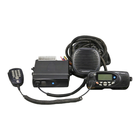
Meteor Communications Corporation MCC-545C Installation guide

FCC ID: BIB5450500101
EXHIBIT VIII
OPERATION AND MAINTENANCE
OF THE
MCC-545C
PACKET DATA RADIO

FCC ID: BIB5450500101
EXHIBIT VIII
OPERATION AND MAINTENANCE
OF THE
MCC-545C PACKET DATA RADIO
MAN-OM-545C
January 2001
Meteor Communications Corporation
8631 So.212th St..
Kent, WA 98031
Tel: (253) 872-2521
Fax: (253) 872-7662
E-mail: mcc@meteorcomm.com
2000 by Meteor Communications Corporation
all rights reserved

FCC ID: BIB5450500101
EXHIBIT VIII
This page MUST be inserted for any copy of this manual going to the United Kingdom.
WARNING WARNING WARNING
Certain power transistors used in this equipment and their associated heatsink components are
manufactured partly or wholly from a beryllium compound. Normally these can be handled
without risk of toxicity, but there is a toxic hazard if dust or finely-divided particles of the
material are inhaled or enter the body through a cut. Consequently, great care must be taken, and
hands must be washed after handling.
Any cuts or abrasions on the hands must be covered by dressings while such components are
being handled. If beryllium dust does enter the skin through a cut or abrasion, the affected part
must be washed thoroughly and treated by a doctor.
Components containing beryllium may only be machined, cut, abraded, or heated above 400 C
under strictly controlled conditions approved by the appropriate Safety Authority.
Disposal of Beryllium
Disposal of faulty components must be carried out according to special arrangements. Should a
component containing Beryllium be broken, its parts and particles must be gathered carefully
using a moistened tissue (preferably while wearing plastic or rubber gloves), placed in a plastic
bag together with any contaminated materials, sealed, labeled, and disposed of in a manner
approved of by the Safety Authority.
Beryllium Components in MCC-545C RF Power Components
RF power components in the modules listed below incorporate some Beryllium within the
transistor package and must be handled as specified in the above warning notice.
TRANSISTOR CIRCUIT MODULE MANUFACTURER REFERENCE
545C 100W Transmitter (54505302-01) Advanced Semi Corp
Motorola Q1,Q4
Q2

FCC ID: BIB5450500101
EXHIBIT VIII
GENERAL WARRANTY
Meteor Communications Corporation (MCC) warrants that its products conform to the
published specifications and are free from manufacturing and material defects for one year after
shipment. Warranty-covered equipment that fails during the warranty period will be promptly
repaired at MCC’s facility in Kent, Washington.
International customers shall pay shipping costs to the MCC facility, with Seattle as the point of
U.S. entry. MCC shall pay incoming U.S. duty fees. MCC shall pay for shipping costs to return
the equipment to the customer, with the customer paying any and all return duty fees.
This warranty is contingent upon proper use of the equipment and does not cover equipment that
has been modified in any way without MCC’s approval or has been subjected to unusual
physical or electrical stress, or on which the original identification marks have been removed or
altered.

FCC ID: BIB5450500101
EXHIBIT VIII
REVISION PAGE
Document Title MCC-545C INSTALLATION AND OPERATIONS Manual
Document Number:
Revision # Date Revision
Redline 11/10/2000 Redline Release
01/03/2001 Initial Release
A
B
C
D
E
F
G
H
I

DESCRIPTION 2-1
O&M of the MCC-545C PACKET DATA RADIO
12/2000
TABLE OF CONTENTS
Title Page
1.0 INTRODUCTION................................................................................................... 1-1
1.1 Organization..................................................................................................... 1-1
1.2 Support Documents.......................................................................................... 1-2
1.3 Conventions...................................................................................................... 1-2
2.0 DESCRIPTION....................................................................................................... 2-1
2.1 General Description............................................................................................. 2-1
2.2 Send and Receive Messages................................................................................ 2-1
2.3 Data Logging....................................................................................................... 2-1
2.4 Position Location................................................................................................. 2-2
2.5 Maintenance Features.......................................................................................... 2-3
2.6 Hardware Organization and Layout.................................................................... 2-3
2.6.1 MCC-545C Transceiver Assembly......................................................... 2-4
2.6.2 MCC-545C Power Amplifier.................................................................. 2-7
2.6.3 MCC-545C Microprocessor.................................................................... 2-7
3.0 INSTALLATION .................................................................................................... 3-1
3.1 Site Selection...................................................................................................... 3-1
3.1.1 External Noise/Interference .................................................................... 3-1
3.1.2 Horizon Angle......................................................................................... 3-3
3.1.3 Power Source........................................................................................... 3-3
3.1.4 Site Dimensions....................................................................................... 3-3
3.1.5 Antenna Considerations .......................................................................... 3-3
3.2 Equipment Installation........................................................................................ 3-5
3.2.1 Antenna Installation ................................................................................ 3-5
3.2.2 Cable Connections................................................................................... 3-5
3.2.2.1 DC Power................................................................................... 3-8
3.2.2.2 Antenna...................................................................................... 3-8
3.2.2.3 Ground Wire............................................................................... 3-8
3.2.2.4 Operator Port.............................................................................. 3-8
3.2.2.5 Data Port .................................................................................... 3-8
3.2.2.6 Auxiliary (AUX) Port ................................................................ 3-8
3.3 Power-Up Sequence............................................................................................ 3-9
3.3.1 Internal Battery........................................................................................ 3-9
3.3.2 Power On................................................................................................. 3-9
3.3.3 Set Unit ID............................................................................................... 3-11
3.3.4 Set and VerifyTx/Rx Frequencies........................................................... 3-11
3.3.5 Perform RF Test...................................................................................... 3-12
4.0 OPERATIONS ...................................................................................................... 4-1
4.1 Getting Started..................................................................................................... 4-1
4.1.1 Command Entry and Editing................................................................... 4-1
4.1.2 Unit Name and Station ID....................................................................... 4-2

DESCRIPTION 2-2
O&M of the MCC-545C PACKET DATA RADIO
12/2000
Title Page
4.1.3 HELP Command .................................................................................... 4-2
4.1.4 System Time and Date............................................................................ 4-2
4.2 Station Operational Parameters........................................................................... 4-3
4.2.1 Configuring the MCC-545C.................................................................... 4-3
4.2.2 Selecting MCC-545C Remote/Master Operation ................................... 4-5
4.2.3 Selecting Network Parameters................................................................ 4-5
4.2.4 Selecting the Burst Monitor .................................................................... 4-7
4.2.5 Controlling the Hourly Statistics Report................................................. 4-8
4.2.6 Scheduling MCC-545C Events............................................................... 4-8
4.2.7 Setting Timeout Durations ...................................................................... 4-9
4.2.8 Setting Frequencies ................................................................................. 4-9
4.2.9 Defining Data Relays.............................................................................. 4-10
4.2.10 Scaling A/D Readings............................................................................. 4-11
4.3 Sending and Receiving Messages ....................................................................... 4-12
4.3.1 Entering and Deleting Messages............................................................. 4-12
4.3.2 Sending Commands to Remote Stations................................................. 4-14
4.3.3 Editing Messages..................................................................................... 4-14
4.3.4 Transmitting Messages............................................................................ 4-15
4.3.5 Receiving Messages............................................................................... 4-16
4.3.6 Examining/Revising Messages Queues................................................... 4-16
4.3.7 Examining Message Statistics................................................................. 4-18
4.3.8 Entering Canned Messages...................................................................... 4-18
4.3.9 Printing Canned Messages ...................................................................... 4-19
4.4 Data Loggers ....................................................................................................... 4-19
4.5 Reporting Position Location................................................................................ 4-19
4.6 Master Simulator Mode....................................................................................... 4-20
4.7 Examining Station Statistics................................................................................ 4-22
4.8 Configuring an RF Network................................................................................ 4-23
4.8.1 Types of Networks .................................................................................. 4-23
4.8.1.1 Meteor Burst Networks............................................................ 4-24
4.8.1.1.1 Full Duplex Network.............................................. 4-25
4.8.1.1.2 Half Duplex Network............................................. 4-26
4.8.1.1.3 Master Probe/Transpond Role................................ 4-26
4.8.1.1.4 Master Active/Passive Role.................................... 4-26
4.8.1.2 Line-of-Sight Networks............................................................ 4-27
4.8.1.2.1 Multi-Master Mode ................................................ 4-28
4.8.1.2.2 Base/Repeater Mode .............................................. 4-28
4.8.2 Remote to Master Assignment................................................................ 4-30
4.8.2.1 Fixed Master Selection............................................................. 4-30
4.8.2.2 Preferred Master Selection....................................................... 4-30
4.8.2.3 Automatic Master Selection..................................................... 4-32
4.8.3 Destination Considerations...................................................................... 4-32
4.8.4 Source and Group Routing...................................................................... 4-33
4.8.5 Network Parameters................................................................................ 4-34

DESCRIPTION 2-3
O&M of the MCC-545C PACKET DATA RADIO
12/2000
Title Page
4.9 Command Reference List.................................................................................... 4-37
APPENDIX A
Command Printouts
Unsolicited Printouts
APPENDIX B
Data Logger Interface
APPENDIX C
GPS Interface
APPENDIX D
Application Note: MCC-545C PACKET DATA RADIO Warning Software
APPENDIX E
Application Note: CR10X Data Logger
APPENDIX F
Event Programming
LIST OF FIGURES
Figure Page
2.1 MCC-545C Photograph............................................................................................. 2-2
2.2 MCC-545C Block Diagram....................................................................................... 2-5
2.3 MCC-545C Outline Drawing.................................................................................... 2-6
3.1 Remote Station Antenna Height for Meteor Burst.................................................... 3-4
LIST OF TABLES
Table Page
2.1 MCC-545C General Specifications........................................................................... 2-8
2.2 MCC-545C Receiver Specifications......................................................................... 2-8
2.3 MCC-545C Transmitter Specifications..................................................................... 2-9
2.4 MCC-545C Multiprocessor Specifications............................................................... 2-9
3.1 MCC-545C Interface Connections............................................................................ 3-6
4.1 MCC-545C Scaling Factors...................................................................................... 4-11
4.2 MCC-545C Commands............................................................................................. 4-40

DESCRIPTION 2-4
O&M of the MCC-545C PACKET DATA RADIO
12/2000

DESCRIPTION 2-5
O&M of the MCC-545C PACKET DATA RADIO
12/2000
1.0 INTRODUCTION
The MCC-545B PACKET DATA RADIO is part of a Meteor Burst Communications System
(MBCS) that allows short and long range communications between any two Stations in the
system. The system offers continuous radio signal propagation via ground wave and meteor
burst. Ground wave covers short distances, up to 100 km (60 miles). Meteor burst covers longer
distances, up to 1,600 km (1,000 miles), reflecting signals off ionized electron trails created by
meteors entering the atmosphere at a height of about 100 km (60 miles) above the earth's surface.
These trails, called bursts, are random but predictable in number and last from a few
milliseconds to several seconds. During this time, information can be exchanged between two
Stations. The height of the trails (60 miles) gives the system its 1,000 mile range.
1.1 Presentation
This manual is divided into five major sections:
Section 2. DESCRIPTION
Discusses specifications of each module included in the 545B.
Section 3: INSTALLATION
Presents a brief outline of installation procedures for the 545B. Includes
considerations for set-up and cabling, as well as power-up procedures.
Section 4: OPERATION
Outlines operating procedures for hardware and software.
Appendix A contains printouts of 545B commands and command responses.
Appendix B contains for interfacing the Pharos Marine Data Acquisition Unit.
Appendix C contains a list of GPS units supported and instructions for interfacing each unit to
the 545B.
Appendix D contains information on configuring the 545B for use in a Flood Warning System.
Appendix E contains information on interfacing to the Campbell Scientific CR10X Data Logger.
Appendix F contains information on the event and I/O programming capability of the 545B.

DESCRIPTION 2-6
O&M of the MCC-545C PACKET DATA RADIO
12/2000
1.2 Support Documents
Customer Specific System Manual
MCC-520B/MCC-520C Operations Manual
1.3 Conventions
The following conventions are used in this manual:
Any system-dependent options are indicated with an "*".
When presented in the text, user commands and computer printout are boldfaced; e.g., Enter
DELETE. Command parameters are presented in lower case; e.g., DEFINE,id. Optional
parameters are enclosed in brackets; e.g., TIME{,hh:mm:ss}
Names of terminal keys are capitalized and enclosed in square brackets when mentioned in the
text; e.g., Press [ESC].
Names of hardware switches, meters, etc. are capitalized; e.g., PWR ON switch.
NOTE
Used for special emphasis of material
IMPORTANT
Used for added emphasis of material.
CAUTION
Signals the operator to proceed carefully.
WARNING! WARNING! WARNING!
Used in cases where failure to heed the message may result in personal injury or equipment
damage.

DESCRIPTION 2-7
O&M of the MCC-545C PACKET DATA RADIO
12/2000

DESCRIPTION 2-8
O&M of the MCC-545C PACKET DATA RADIO
12/2000
2
2.0 DESCRIPTION
2.1 General Description
The MCC-545C Packet Data Radio provides versatile communications from fixed or mobile
sites. The 545C can be used for sending and receiving messages, position reporting, data logging,
or other specific applications. Designed to operate over a fading groundwave and an intermittent
meteor burst communications channel, the unit's low standby-power consumption (<1 watt)
makes it ideal for remote locations or mobile operation.
The 545C features rugged construction in a weather-resistant enclosure that measures 10.6 " x
4.0" x 2.42" and weighs less than 3.5 pounds.
A photograph of the 545C is given in Figure 2.1.
The unit operates in a half-duplex mode and contains a solid state Tx/Rx switch that allows a
common antenna to be shared for both transmit and receive. It can be operated with a single
frequency or on two separate frequencies.
The unit utilizes three phase locked frequency synthesizers to set the Tx and Rx frequencies.
The operator can set the frequency to any authorized frequency (10KHz steps) within a 2 MHz
band. Authorized frequencies can only be set at the factory by trained technicians. A factory
technician is required to retune the transmitter and synthesizer if operation outside a 2 MHz band
is desired. The unit can be factory tuned across the full 37 to 50 MHz band
2.2 Send and Receive Messages
The 545C provides full text message capability. With a portable operating terminal, or a PC
running terminal emulation software, you can exchange messages with any other Remote Station
in the network.
Messages may be plain text or binary data. They can be routed to single or multiple destinations
or, to a Host Computer or Data Center.
2.3 Data Logging
The 545C can be programmed to acquire, store, and transmit data from the various I/O signals
noted below. Any analog or digital input can be used to trigger a transmission or to set a discrete
output level. Output levels can also be set hi or low via a command received from a distant unit.

DESCRIPTION 2-9
O&M of the MCC-545C PACKET DATA RADIO
12/2000
I/O CAPABILITY OF MCC 545C
NAME RANGE QUANTITY
Analog Inputs 0 to +5V 6
Digital Inputs Optical isolated 4
Digital Outputs RS232 (+/- 10V) 2
Digital Outputs 0 to +5V( 10 ma) 3
Digital Inputs 0 to + 5V or +/-10V 2
Relay Outputs Form C 2 amp rating 2
MCC-545C PHOTOGRAPH
FIGURE 2.1
Refer to Appendix E for detailed operation and control of the I/O capability of the MCC 545C.
The MCC can also be connected via an RS232 port to a variety of Data Loggers such as the
Campbell Scientific CR10X or CR23. Data from these loggers can be collected, stored, and
transmitted to a distant unit. Refer to Appendix B and E for a description of data logger
interface.
2.4 Position Location
The 545C delivers location data from either a built 12 channel GPS (optional) or from an
external GPS with NEMA 0183 format, positioning equipment used in mobile units on land, in
the air, and at sea. The 545C sends the position location to a Master or Base Station, which
forwards the information to a Data Center or Host Computer for processing. This data can be
used in dispatch centers, corporate/district offices, and other monitoring Stations for updating

DESCRIPTION 2-10
O&M of the MCC-545C PACKET DATA RADIO
12/2000
map displays or additional functions. Refer to Appendix B for a description of the GPS
commands.
2.5 Maintenance Features
An operator terminal or a remote command from a distant unit can also be used to read and
display the 545C's status such as radio propagation channel statistics, battery voltage during
transmission (loaded), battery voltage when not transmitting (unloaded), RF forward and
reflected power (checks antenna), and receiver noise levels. It can also be used to display and
configure the 545C's operating characteristics, as detailed in Chapter 4.
An internal Li ion battery is used to maintain the internal real time clock and battery backed
RAM. This battery is capable of operating the clock in a power down state for a period of
approximately 6 months. This battery should be removed if the unit is stored without power for
extended periods of time.
2.6 Hardware Organization and Layout
The unit contains five printed circuit assemblies:
A 100 watt all solid-state 2 stage power amplifier.
A 2 watt 2 stage preamplifier and power switch.
A BPSK 4 KB/sec transceiver containing a BPSK receiver, vector phase modulator (+13Dbm
output) and three frequency synthesizers.
A low-power microprocessor controller used to perform radio control and link and network
protocol functions. This assembly also contains a digital signal processor (DSP)and
digital to analog converter (DAC)for generating the in-phase (I) and quadrature-phase
(Q) base band signals required to generate the BPSK RF signal.
An 8 channel GPSreceiver (optional)
The following paragraphs contain a brief description of each of the five main hardware elements
in the 545C. Figure 2.2 presents a block diagram for the 545C. Figure 2.3 presents an outline
drawing showing mounting holes, connectors, and dimensions.

DESCRIPTION 2-11
O&M of the MCC-545C PACKET DATA RADIO
12/2000
2.6.1 MCC-545C Transceiver Assembly
The receiver assembly contains a complete 4K baud Bi Phase Shift Key (BPSK) receiver, a
transmit and receive frequency synthesizer module, and a 4K baud BPSK modulator.
BPSK Receiver
!Input band pass filter (37-50 MHz)
!RF amplifier (17 dB)
!Low pass image filter (Fc=50 MHz)
!Mixer
!IF amplifiers and filters (10.7 MHz)
!Noise blanker
!Mixer, 2nd IF filter and amplifier (100 KHz), and RSSI circuit
!Coherent Costas Carrier Tracking Loop
!BPSK bit detector and clock generator
Synthesizer (1st and 2nd local oscillator and transmit oscillator)
!Reference Oscillator (12.8 MHz +/- 2.5 PPM)
!Tx phase lock loop ( 74-100 MHz output, 20 KHz steps)
!A divide by 2 circuit (37-50 MHz output, 10 KHz steps)
!Rx 1st local oscillator phase lock loop (47.7-60.7 MHz output, 10 KHz steps)
!Rx 2nd local oscillator phase lock loop (10.6 MHz)
!PIC Microcontroller
BPSK Modulator
1. I/Q Vector Phase Modulator (BPSK)
2. Pre amplifier (+13 DBM output)
All components are located on a 8.5”by 3.5” two sided printed circuit board. All components are
soldered in (surface mounted). As an option the board can be conformal-coated with an acrylic
encapsulate that contains a tropicalizing, anti-fungal agent to increase durability and provide
protection against moisture and contamination.

DESCRIPTION 2-12
O&M of the MCC-545C PACKET DATA RADIO
12/2000
MCC 545C BLOCK DIAGRAM
FIGURE 2.2
OPTION GPS
4.192 PROCESSOR
NB ENABLE ANT
54505304-01
MHZ
BPSK TRANSCEIVER OSC GPS
PIC
54506303-01 NOISE BLANKER PCI BUS
MICRO
CONTROL CONTROL
TO SYNTH
2ND IF 14.2 MHZ RS 232
CERAMIC LOG ONE
COMP PROCESSOR
VCXO
2 ND IF TPFILTER AMP SHOT 4 OPER
CTL 0
LPFLBPF
DATA
QUADGATE 4.2 MHZ
FC=50 MHZ 10.7 MHZ 139-50 MHZ USART AUX
A1 LIMITED COSTAS 2
RX DATA
A1BPF1 BPF2 CERAMIC FIRST IF 10.7 MHZ USARTFILTER RX CLK
CERAMICLO1 I&D DATA RXLOCK
FILTER FILTER FILTER
SWITCH CRYSTAL COSTAS
CRYSTAL BPSK BASEBAND
16 DB 16 DB A2 A2 A2 PLL FLASH
BRATE
DET RF
VCOFr+10.7 MHZ 16 DB MAINRSSI
AD607 LOCK MEMORY
DUAL
DC CTRL PHASE LOCKED 1MEG X 16
PROCESSOR
DET RF
DC CTRL IF AMP/DETECTOR
LOOP I/O
68332VCO TCXO PHASE DC CTRL VCO
LOCKED
REF OSC
Ft LO2 114.9 MHZ SP
LOOP
FREQ DEV = +/- 2400 HZ COMPARE CONN
RAM
12.8/10.0 MHZ
GMSK MODULATION 0 DBM 512K X 16
RX ENABLE
PIC CONTROL
DATA RATE = 9600 BAUD /2 44 PIN
SYNTH LOCKSYNTH LOCK
BT = .5 IMEG (OPTIONAL)
III
COMPLEX (3)
DISCRETE
QQD/A
PHASE QOUTPUTS
DUAL
MODULATOR TXKEY MODULATOR OUT (2)
RELAY
A1 OUTPUTS
+13 DBM
ERA-5SM
RX INPUT (4)
OPTO
INPUTSDATA+12BATT 5.7VRX
CO-AX SYNC
CO-AX ANALOG INPUTS (6)
TX DATA
TX KEY
V_R TXLIMITEMI DET RF
I/O7 A/D
V_F TEMP
EMI 10 BIT
VF
POWER 11 CHVRVCC3 CONTROL & SWITCH
EMI +12VBATT
TX CLK
VCC2
EMI
I DATAVCC1 BRATE 9600 BAUD
5.7V
VR VF 5.7VPR
SWITCH DSP
LPF .020W REGULATOR
2W
100W
DIR 20W
T/R .1W
G=7DB G=13DB G=10DBG=10DB
FC = 60 MHZ
COUPLER SWITCH PROCESSOR
VHB121-12T54505305-01 19.6608 MHZ
Q DATA
VLB1-12
FINAL POWER AMP 54505306-01 FRONT END PA & POWER CONTROL
VLB100-12 MRF 455 CLK
COUNTER
F1/16
F1
CO-AX
+12 VOLT POWER 12 V BATT
PROCESSOR RUN (ON) LED (FLASH) LED
TX POWER OK = AMBER LED VSWR = RED LED LED
ANTENNA BNC

DESCRIPTION 2-13
O&M of the MCC-545C PACKET DATA RADIO
12/2000
MCC 545C OUTLINE DRAWING
FIGURE 2.3

DESCRIPTION 2-14
MCC-545C PACKET DATA RADIO
12/2000
2.6.2 MCC-545C Power Amplifier
The power amplifier assembly contains two printed circuit boards. One board, the 100 watt
power amplifier, is mounted inside an aluminum enclosure to provide RF shielding between the
low level phase lock loop synthesizers and the high power output. This board contains a T/R
switch for half-duplex operation, a harmonic low pass filter, and a dual directional coupler for
power level control.
The second board contains two low level amplifiers which amplify the 20 milliwatt input signal
from the modulator to a two watt level required by the final power amplifier stage.
All transmitter components are located on a two 4.0" x 3.5’’ printed circuit boards. All
components are soldered in place. As an option the boards can be conformal-coated with an
acrylic encapsulate that contains a tropicalizing, anti-fungal agent to increase durability and
provide protection against moisture and contamination.
Both printed circuit boards are mounted to an aluminum heat sink assembly.
2.6.3 MCC-545C Microprocessor
The microprocessor is a Motorola-based, embedded computer housed on a single PCB that
contains:
!512K x 16 of non-volatile flash memory for program storage
!Additional 512K x 16 of non-volatile flash memory for parameter storage
!1024K x 8 of static RAM for data storage (optionally 2048K x 8)
!External RS-232 I/O ports (3)
!Internal TTL GPS port
!Transmitter communication port
!Receiver communication port
!10-bit 11 channel A/D converter (6 channels available for external sensors)
!Real-time clock
!Power fail detection circuitry
!Digital Signal Processor with D/A converters
!Optically isolated digital inputs (6)
!Form C Relay Outputs (2) with current rating of 2 amps.
All I/O ports are RS 232 compatible and can be programmed to adapt to various customer
protocols. The DATA port contains full flow control hardware lines.
The A/D converter measures TX forward and reverse power, battery voltage, antenna noise
voltage, transmitter board temperature, and 6 channels of 0-5V external sensor inputs.
All processor components are located on a 198mm x 95mm (7.8” x 3.75”). All components are
soldered in place usingthe latest in surface mount technologies. As an option the board can be

DESCRIPTION 2-15
MCC-545C PACKET DATA RADIO
12/2000
conformal-coated with an acrylic encapsulate that contains a tropicalizing, anti-fungal agent to
increase durability and provide increased protection against moisture and contamination.
Specifications for the unit and the individual circuit boards are given in Tables 2.1 through 2.4.
MCC-545C GENERAL SPECIFICATIONS
CHARACTERISTIC SPECIFICATION
Dimensions 10.6”L X 4.0”W X 2.42”H
Weight 3.5 lbs.
Temperature Range -30°to 60°C (-22°to 140°F)
Power Requirements 12 VDC Nominal (10-14 VDC)
Standby: 80 ma (Continuous)
Transmit: 25 Amps Nominal (100 msec)
TABLE 2.1
MCC-545C RECEIVER SPECIFICATIONS
CHARACTERISTIC SPECIFICATION
Frequency 37-50 MHz .0005%
Synthesized 10KHz steps
Modulation: Type
Rate
Format
GMSK
9.6 kbps and 19.2 kbps
NRZ
Noise Figure < 7 db minimum
Sensitivity: Bit Error Rate < 10-3 at 9.6
kbps -114 dbm
IF Bandwidth (3/80 db) 13/40 KHz typical
RF Bandwidth (3 db) 13 MHz typical
Signal Acquisition Time < 5 msec
3rd Order Intercept Point >- 4 dbm
Image Response Attenuation > 70 db minimum
Spurious Response Attenuation > 70 db minimum
SP Threshold Adjustable from –115 to –106 dbm
Triggered by DET RF and Demodulator Lock
Noise Blanker > 20 db Reduction in Impulse Noise
I/O MCC Standard (Refer to Section 3.2)
TABLE 2.2
Table of contents
