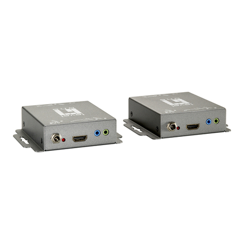
Flextronics MWB1300 User manual

Design. Build. Ship. Service
MWB1300
Wireless Video Extender Kit
User’s Guide
Version 3.12.100

pg. 2 Copyright © 2009 Flextronics Special Business Solutions | Design. Build. Ship. Service
Table of Contents
1Preface .................................................................................................................................................... 4
Who should use this guide .......................................................................................................... 4
Support Information ..................................................................................................................... 4
2Introduction .......................................................................................................................................... 5
3Knowing your MWB1300 Kit............................................................................................................. 7
Package Contents .......................................................................................................................... 7
Hardware Overview..................................................................................................................... 7
WB1305 connections ............................................................................................................ 8
WS1000 connections ............................................................................................................ 9
Front Panel and LED Status Lights ..................................................................................... 10
4Setting Up your MWB1300 Kit ........................................................................................................ 14
Powering Up your devices......................................................................................................... 15
Pairing your Devices................................................................................................................... 17
Placing and connecting your devices ....................................................................................... 18
Changing Your Computer’s IP Address.................................................................................. 21
5Manage ent - Getting Started ........................................................................................................ 23
Logging into the WB1305 anagement Application......................................................... 24
Navigating the WB1305 anagement Application............................................................ 25
6Managing the MWB1305 Device..................................................................................................... 27
Configuring the WB1305 Device ........................................................................................... 28
Defining Network Settings................................................................................................... 28
Defining Wireless Settings.................................................................................................... 30
Defining QoS Settings ........................................................................................................... 33
Defining Security Settings .................................................................................................... 35
Defining WPS Settings .......................................................................................................... 39

Copyright © 2009 Flextronics Special Business Solutions | Design. Build. Ship. Service pg. 3
Performing Administration.................................................................................................. 41
onitoring the WB1305 Device............................................................................................. 45
Viewing System and Station Parameters............................................................................ 45
Viewing Station Statistics ..................................................................................................... 48
Viewing ulticast Status...................................................................................................... 50
AUpdating the MWS1000..........................................................................................................................53
BTroubleshooting MWB1300 Kit............................................................................................................56
CTechnical Specifications.........................................................................................................................58
DRegulatory Co pliance Infor ation...................................................................................................59
Europe – EU Declaration of Conformity.................................................................................. 59
FCC Requirements for Operation in the United States.......................................................... 59
Federal Communication Commission Statement ............................................................. 59
FCC Warning.......................................................................................................................... 60
FCC RF Radiation Exposure Statement.............................................................................. 60
Industry Canada (IC) Statement ............................................................................................... 60

pg. 4 Copyright © 2009 Flextronics Special Business Solutions | Design. Build. Ship. Service
Preface
Welcome to the Wireless Video Extender solution set from Flextronics. The User’s Guide
will help you to understand the Wireless Video Extender solution, how to install it,
configure it and troubleshoot problems.
Who should use this guide
This User’s Guide assumes that the reader has basic to intermediate computer and internet
skills. All the basic computer networking, Internet, and other information required to
configure the home network and the devices is provided herein.
Support Information
Flextronics Special Buisness Solutions
Hatasia 1 St Ramat Gavriel Ind. Zone .
P.O. Box 23108
igdal Haemek
Israel
Tel.: +972-4-644-8212
Fax: +972-4-604-0850

Copyright © 2009 Flextronics Special Business Solutions | Design. Build. Ship. Service pg. 5
1
Introduction
The Wireless Video Extender solution set enables service providers and consumers to
quickly and simply deploy wireless home networks that can securely deliver multiple
streams of carrier-quality SDTV and HDTV, and any other multimedia content throughout
the home. The solution is optimized toward Quality of Experience (QoE) and performance
consistency in both capacity and coverage.
The Wireless Video Extender solution set includes a “Celeno-Powered” WB-1305
“Access Point” and a WS-1000 “Client” which enable distribution of high-definition
video streams from one central location to a TV set in the house without replacing existing
routers, gateways, set top boxes or laying out new cables across the house.

pg. 6 Copyright © 2009 Flextronics Special Business Solutions | Design. Build. Ship. Service
Figure 1 MWB1300 Kit

Copyright © 2009 Flextronics Special Business Solutions | Design. Build. Ship. Service pg. 7
2
Knowing your MWB1300 Kit
Package Contents
Your WB1300 Kit contains the following items:
1. WB1305 Wireless Video Extender “Access Point”
2. WS1000 Wireless Video Extender “Client”
3. Two CAT5 cables
4. 1 Power Transformer for the WB1305 device
5. 1 Power Transformers for the WS1000 device
6. Quick Installation Guide
Hardware Overview
The WB1300 Kit is comprised from a WB1305 access point device and a WS1000
client device .
The WB1305 is powered by Celeno’s CL1300 WiFi chipset that employs sophisticated
algorithms and techniques such as implicit Beam Forming to reliably stream High
Definition video to any location in the home. The WB1305 connects to the video source
that can be a gateway or a cable/DSL modem.
The WS1000 is a standard “off the shelf” WiFi client device. The WB1000 connects to
the video receiving set top box device.
The WB1300 devices has been designed to be placed on a desktop. All of the cables exit
from the rear of the devices. The status display LEDs are located at the front of the devices
and are easily visible.

pg. 8 Copyright © 2009 Flextronics Special Business Solutions | Design. Build. Ship. Service
MWB1305 connections
Figure 2: MWB1305 – Rear Panel
The following table describes the connectors on the rear panel of the WB1305 device:
Table 1: MWB1305 Rear Panel – Connectors
Name Description
Ethernet Data and anagement Ethernet port.
WPS Wireless Protected Setup(WPS) button.
Power In DC power input. 12 VDC.

Copyright © 2009 Flextronics Special Business Solutions | Design. Build. Ship. Service pg. 9
MWS1000 connections
Figure 3: MWS1000 – Rear Panel
The following table describes the connectors on the rear panel of the WS1000 device:
Table 2 - MWS1000 Rear Panel – Connectors
Name Description
Ethernet Data and anagement Ethernet port.
WPS Wireless Protected Setup(WPS) button.
Power In DC power input. 5 VDC.

pg. 10 Copyright © 2009 Flextronics Special Business Solutions | Design. Build. Ship. Service
Front Panel and LED Status Lights
Figure 4 - MWB1305/ MWS1000 – Front Panel shows the front view of the WB1305 and
WS1000 devices.
Figure 4 - MWB1305/ MWS1000 – Front Panel

Copyright © 2009 Flextronics Special Business Solutions | Design. Build. Ship. Service pg. 11
The following table describes the LED indications on the front panel of the WB1305
Device.
Table 3 - WB1305 LEDs
Name Color Description
Solid Green The device is powered on. Power
Off The device is powered off.
Solid Green The LAN port is connected and has a link. LAN
Off The LAN port is either not connected or has no
link.
Solid Green At least one WS1000 device is associated with
the WB1305 AP.
Flashing Green WPS pairing is in progress. This is a temporary
state that lasts no longer then 2 minutes.
WLAN
Off No WS1000 devices are associated with the
WB1305 AP.
Solid Green The wireless link conditions are excellent and all
of the associated WS1000 devices can
consistently receive high definition video streams.
Flashing Green WPS pairing has finished successfully. This is a
temporary state that lasts for 30 seconds.
Solid Yellow The wireless link conditions are fair and all of the
associated WS1000 devices can consistently
receive standard definition video streams, but at
least one associated WS1000 device is unable to
consistently receive high definition video streams.
Flashing Yellow WPS pairing has failed. This is a temporary state
that lasts for 30 seconds.
Link Quality
Off The wireless link conditions are poor and at least
one associated WS1000 device cannot receive
video at all.

pg. 12 Copyright © 2009 Flextronics Special Business Solutions | Design. Build. Ship. Service
The following table describes the LED indications on the front panel of the WS1000
Device.
Table 4 - WS1000 LEDs
Name Color Description
Solid Green The device is powered on. Power
Off The device is powered off.
Solid Green The LAN port is connected and has a link. LAN
Off The LAN port is either not connected or has no
link.
Solid Green The WS1000 device is associated with a
WB1305 AP.
Flashing Green WPS pairing is in progress. This is a temporary
state that lasts no longer then 2 minutes.
WLAN
Off The WS1000 device is not associated with a
WB1305 AP.
Solid Green The wireless link conditions are excellent and the
WS1000 device can consistently receive high
definition video streams.
Flashing Green WPS pairing has finished successfully. This is a
temporary state that lasts for 30 seconds.
Solid Yellow The wireless link conditions are fair and the
WS1000 device can consistently receive
standard definition video streams but not high
definition video streams.
Flashing Yellow WPS pairing has failed. This is a temporary state
that lasts for 30 seconds.
Link Quality
Off The wireless link conditions are poor and the
WS1000 device cannot receive video at all.

Copyright © 2009 Flextronics Special Business Solutions | Design. Build. Ship. Service pg. 13
The following LED combinations describe special indications:
Combination – The Power LED is solid green, the LAN and WLAN LEDs are flashing
green and the link quality LED is flashing yellow. The flashing is simultaneous.
Description – The device is experiencing a severe malfunction. Please contact your service
provider or local dealer.
Combination – The Power LED is solid green, the LAN, WLAN and Link quality LEDs are
flashing green. The lashing is in sequence.
Description – The device is undergoing a software upgrade process.
“Do not unplug the device from the power outlet or reset it while software upgrade is in
progress”.

pg. 14 Copyright © 2009 Flextronics Special Business Solutions | Design. Build. Ship. Service
Setting Up your MWB1300 Kit
Setting up the system involves the following steps:
Powering up your devices
Pairing your devices
Placing and connecting your devices
After performing these steps, you can start streaming High Definition video through the
WB1300 Kit.
Changing your computer’s IP address
After performing this additional step, you can use the WB1305 anagement Application
to configure and manage your WB1305 device. (refer to anaging the WB1305 Device
on page 27).

Copyright © 2009 Flextronics Special Business Solutions | Design. Build. Ship. Service pg. 15
Powering Up your devices
To power up the MWB1305 device:
1. Plug in the 12V A/C adapter and connect it to the WB1305 Access Point device.
Use the recommended AC/DC power adaptor which was supplied in the kit.
“Using a power supply with a different voltage rating then the one included with the
WB1305 device will cause damage and void the warranty for this product”.
Note: There is no On/Off switch. Once you connect the power adapter, the WB1305
device powers up.
2. Wait several seconds while the WB1305 device performs a reset.
Figure 5- Powering up the MWB1305 Device

pg. 16 Copyright © 2009 Flextronics Special Business Solutions | Design. Build. Ship. Service
To power up the MWS1000 device:
1. Plug in the 5V A/C adapter and connect it to the WS1000 Client device.
Use the recommended AC/DC power adaptor which was supplied in the kit:
“Using a power supply with a different voltage rating then the one included with the
WS1000 device will cause damage and void the warranty for this product”.
Note: There is no On/Off switch. Once you connect the power adapter, the WS1000
device powers up.
2. Wait several seconds while the WS1000 device performs a reset.
Figure 6 - Powering up the MWS1000 Device

Copyright © 2009 Flextronics Special Business Solutions | Design. Build. Ship. Service pg. 17
Pairing your Devices
Note: Consult with the quick installation guide that came with your kit to check if the
devices in your kit are already paired, in which case you can skip this step. .
1. Place the WB1305 Access Point and the WS1000 Client devices between 1 to 3
meters from each other.
2. Pair the devices by pressing the WPS button on the WB1305 and WS1000 rear panel
for 5 seconds. You can release the button as soon as the WLAN LED begins flashing.
Figure 7 - Pairing the devices
Note: The WPS buttons should be pressed within 2 minutes period. The buttons can be
pressed in any order.
3. Wait for the pairing process to complete by watching the LEDs on the devices:
While pairing is in progress the WLAN LED is flashing green
After successful pairing the Link Quality LED is flashing green for 30 seconds.
Pairing is in progress Pairing has finished successfully

pg. 18 Copyright © 2009 Flextronics Special Business Solutions | Design. Build. Ship. Service
Placing and connecting your devices
To place and connect your MWB1305 device:
1. Place the WB1305 Access Point device on an easily-accessible surface near the home
gateway or Cable/DSL odem.
2. Plug one end of the Ethernet cable into the LAN port of the gateway device and the
other end into the Ethernet port of the WB1305.
Figure 8 - Connecting and placing the MWB1305 device
3. ake sure that the LAN LED on the WB1305 is turned on:

Copyright © 2009 Flextronics Special Business Solutions | Design. Build. Ship. Service pg. 19
To place and connect your MWS1000 device:
1. Place the WS1000 Client device on an easily-accessible surface near the set top box.
2. Plug one end of the Ethernet cable into the LAN port of the set top box device and the
other end into the Ethernet port of the WS1000.
Figure 9- Connecting and placing the MWS1000 device
3. ake sure that the LAN LED on the WS1000 is turned on:

pg. 20 Copyright © 2009 Flextronics Special Business Solutions | Design. Build. Ship. Service
4. ake sure that the link quality LED is solid green:
If the link quality LED is solid yellow or turned off, try to reposition the device to a more
elevated location and as far as possible from large metallic objects.
Co pleting the installation:
You have finished installing your WB1300 kit. To test your connectivity, turn on the TV
and set top box and watch any available channel.
Note: To install additional WS1000 devices, repeat the above procedure for each new
WS1000 device.
Table of contents

