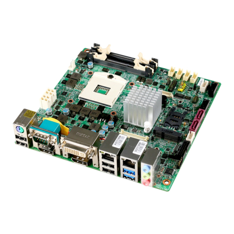
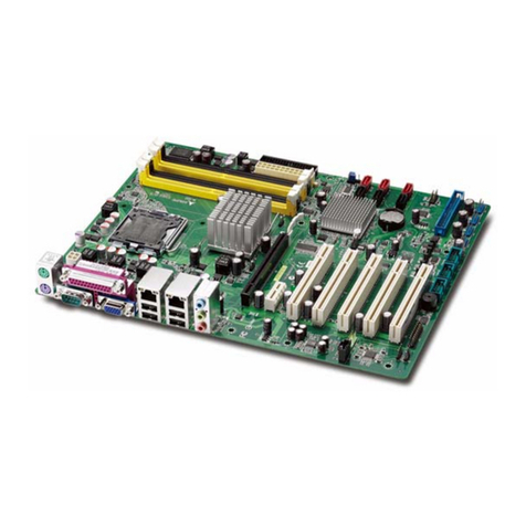
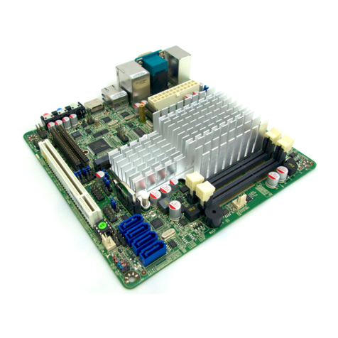
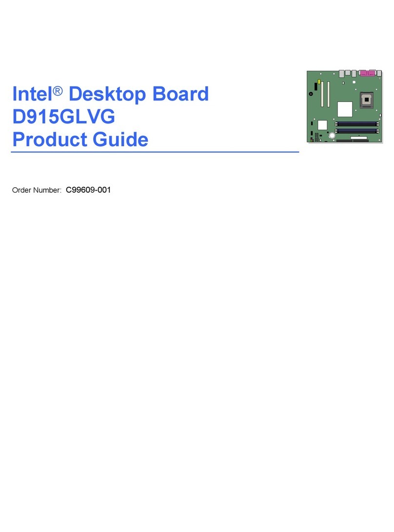
Flextronics Mini P4 Barebone Series User manual

Mini Pentium 4 Barebone
User’s Manual
Version 1.1

ii User’s Manual
Mini P4 Barebone Series

iii
User’s Manual
Preface
FCC Compliance Statement
This equipment has been tested and found to comply with
limits for a Class B digital device, pursuant to Part 15 of
the FCC rules. These limits are designed to provide
reasonable protection against harmful interference in
residential installations. This equipment generates, uses,
and can radiate radio frequency energy, and if not installed
and used in accordance with the instructions, may cause
harmful interference to radio communications.
However, there is no guarantee that interference will not
occur in a particular installation. If this equipment does
cause interference to radio or television equipment
reception, which can be determined by turning the equip-
ment off and on, the user is encouraged to try to correct
the interference by one or more of the following measures:
• Reorient or relocate the receiving antenna
• Move the equipment away from the receiver
• Plug the equipment into an outlet on a circuit different
from that to which the receiver is connected
• Consult an experienced radio/television technician for
additional suggestions
This device complies with Part 15 of the FCC Rules.
Operation is subjected to the following two conditions 1)
this device may not cause harmful interference and 2) this
device must accept any interference received, including
interference that may cause undesired operation.

iv User’s Manual
Mini P4 Barebone Series
Disclaimer
The information in this document is subject to change
without notice. The manufacturer makes no representa-
tions or warranties regarding the contents of this manual
and specifically disclaims any implied warranties of
merchantability or fitness for any particular purpose.
Furthermore, the manufacturer reserves the right to revise
this publication or make changes in the specifications of
the product described within it at any time without notice
and without obligation to notify any person of such
revision.
Trademarks
Microsoft and Windows are registered trademarks of
Microsoft Corp. Intel and Pentium 4 are registered trade-
marks of Intel Corporation. Other product names used in
this manual are the properties of their respective owners
and are acknowledged.
Copyright
This publication, including all photographs, illustrations
and software, is protected under international copyright
laws, with all rights reserved. Neither this manual, nor any
of the material contained herein, may be reproduced
without the express written consent of the manufacturer.
©Copyright 2003

v
User’s Manual
Preface
Table of Contents
1: Introduction ......................................................... 1-1
About This Manual ............................................................ 1-2
Package Contents ............................................................. 1-2
Getting Started .................................................................. 1-1
2: Installation ........................................................... 2-1
Installing a CPU ................................................................. 2-1
Installing System Memory ................................................. 2-7
Installing Internal Peripherals ............................................ 2-9
Installing an IDE drive .................................................. 2-9
Installing a CD-ROM .................................................. 2-10
Completing System Configuration ................................... 2-10
3: External Components ......................................... 3-1
Front Panel ........................................................................ 3-1
Rear Panel ........................................................................ 3-3
4: BIOS Setup ......................................................... 4-1
Running the BIOS Utility .................................................... 4-1
Entering Setup ................................................................... 4-2
System Information ........................................................... 4-2
General Configuration ....................................................... 4-3
Advanced Configuration .................................................... 4-4
System Specific Setup ...................................................... 4-4
Primary / Secondary IDE Drives ........................................ 4-5
Peripherals ........................................................................ 4-6
Power Management .......................................................... 4-6
PCI & PNP ......................................................................... 4-7
Hardware Monitor .............................................................. 4-7
Restore Default Settings ................................................... 4-8
Exit .................................................................................... 4-8
5: Drivers and Utilities ............................................. 5-1
Running the Power Installer Disc ...................................... 5-1
Drivers and Utilities Screen ............................................... 5-1

vi User’s Manual
Mini P4 Barebone Series
Drivers Installation Screen ................................................ 5-1
Software Utility Screen ...................................................... 5-2
Make Driver Screen ........................................................... 5-2
Appendix 1: Hardware Layout .............................. A1-1
Components .................................................................... A1-1
Connectors ...................................................................... A1-1
Jumpers ........................................................................... A1-1
Motherboard Layout ........................................................ A1-2
Motherboard Layout Key .................................................A1-3
JCMOS1: Clear CMOS Jumper ...................................... A1-4
System Memory Socket .................................................. A1-5
CPU Socket & Cooling Fan / Heatsink Frame ................. A1-5
Expansion Slot ................................................................ A1-6
PCI Expanion slot ...................................................... A1-6
AGP Slot .................................................................... A1-6
IDE1, IDE2: IDE Drive Connectors .................................. A1-7
ATX12V Power Connectors ............................................. A1-7
J2, J3: Internal USB Connectors .....................................A1-8
J4: AUX-IN/ CD-IN ........................................................... A1-8
J8: Audio Connector ........................................................ A1-9
JPANEL1: Front Panel Connector ................................... A1-9
JCFAN1, JSFAN1: System Fan Connectors ................. A1-10
Appendix 2: Specifications.................................... A2-1

1 - 1User’s Manual
IntroductionChapter 1
1: Introduction
The mini P4 barebone is a high-performance personal computer
barebones system that supports the Intel® Pentium® 4
processor.The barebone’s motherboard has one DIMM
memory socket that accommodates 200/266 MHz DDR
SDRAM (without AGP slot version) or 200/266/333MHz DDR
SDRAM (with AGP slot version).
The without AGP slot model uses the latest Intel® 845GV chipset
or the Intel® 845GE chipset (with AGP slot version)
to integrate all system control functions.
Features of this system include support for:
•Intel® Pentium® 4 processor
•533/400 MHz system bus
•Up to 1GB DDR SDRAM
•One 32-bit PCI/33 MHz slot (without AGP slot version)
•One onboard AGP slot (with AGP slot version)
•Two USB 2.0 external ports on rear panel (stacked)
For a complete list of specifications, see Appendix 2,
Specifications.

1 - 2 User’s Manual
Mini P4 Barebone Series Chapter 1
About This Manual
This manual’s five chapters and two appendices cover the
following topics:
Chapter 1, Introduction, provides a basic introduction to
the system and package contents.
Chapter 2, Installation, explains basic installation
procedures.
Chapter 3, External Components, describes external
components.
Chapter 4, BIOS Setup, describes setting the BIOS.
Chapter 5, Drivers and Utilities, explains how to use the
bundled software drivers and utilities.
Appendix 1, Hardware Layout, describes the mother-
board layout, components, and configuration
Appendix 2, Specifications, lists the system’s technical
specifications.
Package Contents
The package contains the following items:
• One Barebone
• IDE connector cables
• Power cord
• Three spare Jumper caps
• Power Installer software & utilities disc
• User’s Manual
Inspect the system; if any items are damaged or missing,
contact Anyware Solutions Pte Ltd immediately.

2 - 1
User’s Manual
InstallationChapter 2
2: Installation
This chapter describes installing components and devices
on the barebone’ motherboard. Please review each of
the following procedures before you start. For the location
and description of system components, please refer to
Appendix 1, Hardware Layout.
Getting Started
The package contains the motherboard/chassis assembly,
plus one box containing the Fan/Heatsink, and one box
containing accessories.
1. Unpacking the package.
2. Remove the two smaller boxes and place to one side.
3. Remove the motherboard/chassis assembly, and
discard the foam and plastic packaging – or save it for
recycling.
4. Unscrew the three thumbscrews at the rear of the barebone
and remove the aluminum Housing.
5. Locate the CPU socket.
Installing a CPU
The motherboard supports the Intel Pentium 4 processor.
Follow the procedures below to avoid damaging the CPU
or motherboard.

2 - 2 User’s Manual
Mini P4 Barebone Series Chapter 2
Selecting a Processor
This motherboard supports all Intel Pentium 4 processors.
The motherboard’s BIOS automatically detects the
required settings and configures the CMOS Setup Utility.
Installing the Processor
It is important to review all of the instructions before
beginning the installation procedure. Carefully handle the
processor by its edges, and take all precautions against
electrostatic discharge. The boxed Intel Pentium 4 proces-
sor comes with a Heatsink and Thermal Interface Material
applicator. Non-boxed processors follow the same proce-
dures, but the accessories may have a different appear-
ance. The following illustrations are a generic representa-
tion and may not show the components’ exact appearance.
Note that you install the CPU by reaching your hands and
fingers through the chassis frame to manipulate the CPU
and socket.
1. Unlock the socket by pressing the lever sideways, then
lift it up to a vertical angle.
Step 1

2 - 3
User’s Manual
InstallationChapter 2
2. Position the CPU above the socket such that its
marked corner matches the base of the socket lever.
3. Press it firmly on the socket while you push down the
socket lever to secure the CPU.
Step 2
Step 3

2 - 4 User’s Manual
Mini P4 Barebone Series Chapter 2
4. After installing the CPU you need to apply the Ther-
mal Interface Material (TIM) to the top of the installed
CPU (Fig. 2) and remove the piece of tape from the
Heatsink. The TIM is supplied in an applicator with
the boxed Pentium 4 processors. The TIM secures the
Fan/Heatsink to the CPU. However, if the Fan/
Heatsink already has a patch of TIM on its underside,
you won’t need to apply additional TIM to the CPU
(Fig. 1).
Step 4
Fig. 2
Fig. 1
The heatsink may have thermal interface material attached to the bottom as shown in
Fig.1, or you may need to apply the thermal interface material using a syringe as
shown in Fig.2.
Be careful not to damage the
thermal interface material.
Using the enclosed syringe apply
all of the thermal interface material
to the top of the processor.
mPGA478B

2 - 5
User’s Manual
InstallationChapter 2
Installing the Fan/ Heatsink
To install the Fan/Heatsink assembly:
5. When installing the Fan/Heatsink and clip assembly it
is important to make sure the Fan/Heatsink does not
rotate or twist on the processor. Securing the Fan/
Heatsink while closing the clip lever will ensure the
thermal interface material (TIM) is not damaged and
the processor will operate correctly. The TIM is
attached to the heatsink.
6. Make sure to close the clip levers one at a time. Close
the clip lever (1), while holding the top-side of the
Fan/Heatsink with your other hand (A). Close the clip
lever (2) while holding the top-side of the Fan/
Heatsink with your other hand (B).
Step 5
A
1
Step 6 B
2

2 - 6 User’s Manual
Mini P4 Barebone Series Chapter 2
7. Align the Heatsink and clip assembly with the Reten-
tion Mechanism and place it on the processor. The
Heatsink is symmetrical.
8. With the clip levers in the up position (C), push down
on all four clip frame corners to secure to the Reten-
tion Mechanism hooks (D). Close the clip levers (E).
The levers require force to be completely closed.
Connect the processor fan cable connector to the
motherboard connector.
Step 7 C
D
Step 8
E

2 - 7
User’s Manual
InstallationChapter 2
Installing System Memory
Review this section before installing memory modules.
Memory Specifications
The motherboards has one DIMM module socket that
supports DDR SDRAM. Memory specifications are:
DDR SDRAM*
•PC1600/PC2100 DDR SDRAM (without AGP slot version)
•PC1600/PC2100/PC2700 DDR SDRAM (with AGP slot
version)
•Unbuffered DDR SDRAM modules
•Maximum up to 1GB system memory
Memory configuration options are:
•Supports 64MB, 128MB, 256MB, 512MB, and 1GB
modules
*Note: DDR SDRAM types include:
PC1600 at 200MHz
PC2100 at 266MHz
PC2700 at 333MHz

2 - 8 User’s Manual
Mini P4 Barebone Series Chapter 2
Installing Memory Modules
To install a memory module, you insert a module into its
socket and secure it with the socket retaining arms. The
modules are notched so that you cannot insert them
incorrectly. The BIOS recognizes the installed memory
and configures the CMOS Setup Utility automatically.
Installing Memory Modules
To install memory modules:
1 Unlock a DIMM socket by pressing the retaining clips
outward.
2 Align the “notch” on the memory module to the
“break” on the socket.
3 Firmly insert the module into the socket until the
retaining clips snap back into place and the module is
properly seated.
4 Make sure the memory module is locked on the socket
with both retaining clips.
Notch
Break

2 - 9
User’s Manual
InstallationChapter 2
Installing Internal Peripherals
After installing the CPU, Fan/Heatsink, and memory
modules, you can install internal peripherals such as a
hard disk drive (IDE/HDD), and CD-ROM drive. You
may have to set the jumpers of each internal peripheral to
either Master or Slave mode depending on whether you
install more than one peripheral.
Important: Make sure the 110/220 switch on the back
panel is set to the appropriate voltage.
Installing an IDE drive
To install an IDE drive:
1 Set the required jumpers on the IDE drive according to
the instructions of the manufacturer.
2 Remove the 3-connector peripherals cable from the
accessories box and attach it to the blue connector
IDE1 on the motherboard.
3 Bring the cable up and over the IDE drive and attach
the cable’s middle connector to the IDE drive. With the
cable wrapped over the top of the IDE drive, slide the
drive into the lower chassis port.
Important: The IDE cable must be wrapped over the IDE
Drive to keep it from blocking the fan.
4. Secure the IDE drive to the chassis port by inserting
mounting screws in all the holes and tightening these
screws with a screwdriver.
5. Connect an available power cable from the power
supply unit to the back panel of the IDE Drive. Note
that the power cable is directional and can only fit one
way.

Chapter 2Mini P4 Barebone Series
Installing the IDE Cable between CDROM and HDD
In vertical down direction the IDE Hard Disk Drive
into lower bay and apply screws on each side of the
bay to make sure Hard Disk was secured seated in
correct place.Connect the power and IDE cable to the
IDE Hard Disk. To ensure air-flow quality issue
regarding thermal from CPU, the IDE cable will need
to be placed between IDE Hard Disk Drive and CDROM
CD Rom Drive
Hard Disk Drive
IDE Cable
2 - 10
User’s Manual

User’s Manual 2 - 11
Chapter 2 Installation
Installing a CD-ROM
1Set the required jumpers on the CD-ROM drive
according to the instructions of the manufacturer.
2 Attach the end of the peripherals cable to the CD-
ROM. The peripheral cable now connects both the IDE
drive and the CD-ROM.
3Slide the CD-ROM drive into the upper chassis port.
4. Secure the CD-ROM drive to the chassis by inserting
mounting screws in all the holes and tightening these
screws with a screwdriver.
5. Connect an available power cable from the power
supply unit to the back panel of the IDE Drive. Note
that the power cable is directional and can only fit one
way.
1 2
3 4
Please adjust the button inside the
case to fit the CDROM's button.
Attach the IDE cable and power
cord to the CDROM.
Secure the CD-ROMdrive to the
chassis by insertingscrews.
Slide the CD-ROMdrive into the
chassis from thetop.

2 - 12
User’s Manual
Mini P4 Barebone Series Chapter 2
Completing System Configuration
To complete the system configuration:
1.
Replacing the system housing cover and tighten the
three thumbscrews on the rear panel.
2. Connect external peripherals such as a monitor, a
keyboard, and a pointing device to the back panel.
3. Once you have completed final hardware installation,
you can configure CMOS Setup Utility and Drivers,
see the following chapters.
4. Install an operating system and support software—see
related documentation.
Table of contents
