Fliegl TDK 80 User manual

GB
Operating instructions
TDK tandem three-way tipper
TDK
We are Fliegl.
Translation of original operating instructions

Read these operating instructions prior to first-time start-up
and observe them at all times!
Retain for future reference!

Foreword
Dear valued customer,
Thank you for purchasing the Fliegl tandem three-way tipper.
Fliegl machines and attachments are manufactured with care under continuous monitoring.
The Fliegl tandem three-way tipper you have purchased is a product manufactured to the highest quality
standards.
To avoid accidents, and therefore personal injuries and material damage, you must read and understand
the corresponding cautionary and warning notices in these operating instructions and on the Fliegl
tandem three-way tipper before beginning operation or maintenance of the tandem three-way tipper.
These operating instructions must therefore also be passed on to the operating personnel.
Before putting the Fliegl tandem three-way tipper into operation, every operator must be familiar with
how to handle the machine as described in these operating instructions.
The safety requirements must be strictly followed.
Compliance with safety regulations applicable to your country is also mandatory.
The Fliegl tandem three-way tipper can be attached to different vehicles, such as tractors.
The limits of use are described in this manual.
Any types of operation or use other than those described in these operating instructions, or beyond the
limits of use specified by the manufacturer, are strictly prohibited.


Contents
4
Contents
Foreword..................................................................................................................................................2
Contents ..................................................................................................................................................4
Legal notices............................................................................................................................................9
Identification...........................................................................................................................................10
EC Declaration of Conformity................................................................................................................11
1. User instructions.............................................................................................................................12
1.1 Purpose of this document......................................................................................................12
1.2 Locations in the operating instructions ..................................................................................13
1.3 Illustrations used....................................................................................................................13
1.4 Cross references ...................................................................................................................13
1.5 Terminology: "trailer", "machine", "vehicle" ...........................................................................13
1.6 Figures...................................................................................................................................13
1.7 Scope of the document..........................................................................................................14
1.8 Presentation of safety instructions.........................................................................................14
1.9 Liability and damages............................................................................................................14
1.10 Duty to inform ........................................................................................................................14
2. Basic safety instructions.................................................................................................................15
2.1 Designated use......................................................................................................................18
2.2 Reasonably foreseeable misuse ...........................................................................................19
2.3 Service life of the machine.....................................................................................................20
2.4 Risks when working with the machine...................................................................................20
2.5 Residual risks ........................................................................................................................20
2.6 Obligations of the operator ....................................................................................................20
2.7 Obligations of personnel........................................................................................................21
2.8 Qualification of operating personnel......................................................................................21
2.9 Qualification of specialist personnel ......................................................................................21
2.10 Personal protective equipment..............................................................................................22
2.11 Operational safety..................................................................................................................22
2.11.1 Operation without correct start-up ...................................................................................22
2.11.2 Safeguarding perfect technical condition.........................................................................22
2.11.3 Danger due to machine damage......................................................................................22
2.11.4 Technical limits ................................................................................................................23
2.12 Safety and protective devices................................................................................................23
2.12.1 Emergency stop device....................................................................................................23
2.12.2 Description of additional safety and protective devices...................................................23
2.12.3 In case of faulty protective devices..................................................................................23
2.12.4 Inspecting safety and protective devices.........................................................................23

Contents
5
2.13 Workstation of operating personnel....................................................................................... 24
2.14 Danger areas......................................................................................................................... 24
2.14.1 Safety distance from overhead lines ............................................................................... 25
2.15 Machine identification............................................................................................................ 25
3. Description of the machine............................................................................................................. 27
3.1 Applications........................................................................................................................... 27
3.2 Design variants –standard.................................................................................................... 27
3.3 Functional description ........................................................................................................... 28
3.4 Layout of the machine........................................................................................................... 29
3.5 Assemblies and components ................................................................................................ 30
3.6 Technical data –standard equipment................................................................................... 33
4. Transport and installation............................................................................................................... 34
4.1 Basic requirements................................................................................................................ 34
4.2 Supply and installation .......................................................................................................... 35
4.2.1 Drawbar eye connection.................................................................................................... 35
4.2.2 Establishing the electrical connection ............................................................................... 35
4.2.3 Compressed air supply...................................................................................................... 36
4.2.4 Establishing hydraulic connections ................................................................................... 37
5. Start-up........................................................................................................................................... 38
5.1 First-time start-up .................................................................................................................. 38
5.2 Check before start-up............................................................................................................ 38
5.3 Returning to service............................................................................................................... 38
6. Preparation and setup.................................................................................................................... 39
6.1 Draw gear.............................................................................................................................. 39
6.1.1 Draw gear with top/bottom attachment [from TDK 140].................................................... 39
6.1.2 Hydraulically sprung draw gear [TDK 255]........................................................................ 39
6.1.3 Draw gear with overrun brake........................................................................................... 39
6.1.4 Ball head coupling............................................................................................................. 40
6.1.5 Installing forced steering on the towing vehicle (optional)................................................. 40
6.2 Setting up the forced steering (optional) ............................................................................... 42
6.3 Overrun brake mechanism.................................................................................................... 44
6.4 Compressed air brake system with ALB, brake force regulator (optional)............................ 45
6.5 Hydraulic brake (optional) ..................................................................................................... 46
6.5.1 Hydraulic brake system without load adjustment valve..................................................... 46
6.5.2 Hydraulic brake with load adjustment valve...................................................................... 46
6.6 Parking brake ........................................................................................................................ 47
6.6.1 Farmer stop –parking brake ............................................................................................. 47
6.6.2 Hand brake lever –overrun brake..................................................................................... 47
6.6.3 Hand brake lever (detachable brake) –parking brake...................................................... 48
6.7 Electrical systems.................................................................................................................. 48

Contents
6
7. Use and operation..........................................................................................................................49
7.1 Trailer operation.....................................................................................................................49
7.1.1 Before operation ................................................................................................................49
7.1.2 Setting up the trailer coupling on the towing vehicle .........................................................49
7.1.3 Coupling the trailer.............................................................................................................50
7.1.4 Conducting a trial run.........................................................................................................51
7.1.5 Uncoupling the trailer.........................................................................................................51
7.2 Working with the machine......................................................................................................52
7.2.1 General safety and operating instructions.........................................................................52
7.2.2 Loading the trailer..............................................................................................................53
7.2.3 Emptying the trailer............................................................................................................53
7.2.4 Using the side panels ........................................................................................................54
7.2.5 Tipping linchpins................................................................................................................55
7.2.6 Tipping processes..............................................................................................................55
8. Basic equipment (standard, optional).............................................................................................56
8.1 Side panel..............................................................................................................................56
8.1.1 Base side panel .................................................................................................................56
8.1.2 First and second attachment .............................................................................................56
8.2 Rear panel .............................................................................................................................56
8.2.1 Rear panel (base side panel ) with grain hatch.................................................................56
8.2.2 Gravel flap version.............................................................................................................57
8.3 Supporting mechanism..........................................................................................................57
8.4 Flange couplings....................................................................................................................57
8.5 Underride guard.....................................................................................................................58
8.6 Central locking.......................................................................................................................58
8.6.1 "Rear" version....................................................................................................................58
8.6.2 "Side" version.....................................................................................................................59
8.7 Mechanical stopcock for hydraulics (maintenance work)......................................................60
9. Accessories ....................................................................................................................................61
9.1 Reversing/monitoring camera................................................................................................61
9.2 Marker lights ..........................................................................................................................61
9.3 Side panel tension springs.....................................................................................................61
9.4 Side panel boom chains with storage box.............................................................................61
9.5 Shunting coupling ..................................................................................................................62
9.6 Automatic trailer coupling ......................................................................................................62
9.7 Tensioning chain for steel side panel....................................................................................62
9.8 Removable rear exhaust pipe with outlet spout.....................................................................63
9.9 Removable discharge chute..................................................................................................63
9.10 Side panel stabiliser [tensioning strap]..................................................................................63
9.11 Side panel support.................................................................................................................63

Contents
7
9.12 Bracket for folded side panel................................................................................................. 63
9.13 Roll-off tarpaulin with operating platform............................................................................... 64
9.14 Side panel.............................................................................................................................. 64
9.14.1 First attachment............................................................................................................... 64
9.14.2 Second attachment.......................................................................................................... 64
9.15 Hydraulic rear panel (optional) .............................................................................................. 65
9.16 Supply connections for 2nd trailer......................................................................................... 65
9.17 Bridge support for maintenance work.................................................................................... 66
10. Service and maintenance.......................................................................................................... 67
10.1 Customer service................................................................................................................... 67
10.2 Replacement parts ................................................................................................................ 67
10.3 Fliegl VIN (vehicle ID number) and type plate....................................................................... 68
10.4 Operational maintenance ...................................................................................................... 69
10.4.1 General instructions for maintenance.............................................................................. 69
10.4.2 Cleaning the vehicle ........................................................................................................ 70
10.4.3 Corrosion protection ........................................................................................................ 71
10.4.4 Lubrication schedule........................................................................................................ 71
10.4.5 Tyres and wheels............................................................................................................. 72
10.5 Maintenance of the brake system ......................................................................................... 74
10.5.1 Maintenance of the compressed air brake system.......................................................... 74
10.6 Troubleshooting and fault elimination.................................................................................... 76
10.6.1 List of warning and fault signals ...................................................................................... 76
10.7 Decommissioning.................................................................................................................. 78
10.7.1 Temporary shutdown....................................................................................................... 78
10.7.2 Storage conditions........................................................................................................... 78
10.7.3 Disassembly and final shutdown ..................................................................................... 78
10.7.4 Scrapping and recycling .................................................................................................. 78
11. Standard tipper hydraulics......................................................................................................... 79
12. Brake system............................................................................................................................. 80
13. Electrics..................................................................................................................................... 81
13.1 Contact assignment plan....................................................................................................... 81
13.2 Rear light versions................................................................................................................. 81
14. Axles.......................................................................................................................................... 82
14.1 Axle assemblies..................................................................................................................... 82
14.1.1 Gigant tandem assembly................................................................................................. 82
14.1.2Gigant Plus tandem assembly......................................................................................... 82
14.1.3Titan tandem assembly ................................................................................................... 82
14.2 Axle maintenance work ......................................................................................................... 82
15. Appendix.................................................................................................................................... 83
15.1 Volumetric weights for loosely stacked goods ...................................................................... 83

Contents
8
15.1.1 Agricultural products ........................................................................................................83
15.1.2 Fertiliser ...........................................................................................................................83
15.1.3 Construction materials .....................................................................................................83
15.1.4 Firewood ..........................................................................................................................83
15.2 Conversion table....................................................................................................................84
16. Index..........................................................................................................................................85

Legal notices
9
Legal notices
1. When the tandem three-way tipper is delivered, check immediately to determine whether the
machine is complete. State any complaints to the freight forwarder, have them certified on the
delivery documents and inform the delivering plant within 14 days after you become aware of the
problem (see "Scope of delivery").
2. The manufacturer is liable for technical defects. The owner is liable for defects that were caused
by improper operation.
The warranty period is 1 year from delivery.
3. At our discretion, the warranty will either cover the cost of repair of the faulty part or replacement
of the part, or delivery of the part from the factory, carriage due. Any other claims for
compensation (such as for losses due to business interruption) are expressly excluded.
4. The warranty will be invalidated if the attachment or device is modified by installing third-party
parts without our knowledge or prior agreement, especially if improper modifications were made.
5. The warranty will also be invalidated if a defect is not rectified completely and correctly
immediately after it is discovered. Repairs required for functional reasons need our prior approval
if a claim is to be made for full or partial compensation of expenses.
6. Liability is excluded for damage to the tandem three-way tipper resulting from exceeding the
allowable working capacity or transport speed. The warranty does not cover natural wear,
damage resulting from negligent or improper handling of the machine, or storage and corrosion
damage.
7. Parts not manufactured by ourselves are covered by the warranty provided by the relevant
manufacturer. Machine parts for which claims are made under the terms of the warranty must be
sent without delay to our address in Mühldorf for the purpose of material examination to
determine the damage. If a replacement is made, these parts become our property.
8. Legal warranty provisions also apply to the Fliegl tandem three-way tipper.

Identification
10
Identification
Machine identification data
Manufacturer:
Fliegl Agrartechnik GmbH
Product:
Tandem three-way tipper
Type:
TDK 80, TDK 110, TDK 140, TDK 160,
TDK 200, TDK 255, TDK 80 VR FOX,
TDK 100 VR FOX, TDK 140 FOX,
TDK 160 FOX, TDK 200 FOX
Serial number:
WGJXXXXXXXXXXXXXX
Manufacturer details
Fliegl Agrartechnik GmbH
Bürgermeister-Boch-Straße 1
84453 Mühldorf am Inn, Germany
Telephone: +49 (0)8631 307 - 0
Fax: +49 (0)8631 307 - 550
E-mail: info@fliegl.com
Internet: www.fliegl.com
Formal details of operating instructions
Document no.:
1-009B06203.1
Version/revision:
3.1
Creation date:
12/07/2016
Last revision:
14/07/2020
Language of original operating instructions: German
(Translation of original operating instructions)
Copyright Fliegl, 2020. All rights reserved.
Reproduction, in whole or in part, is only permitted with the approval of Fliegl.
We are constantly developing and enhancing our products and therefore reserve the right to make changes to
them without prior notification.
This may result in differences in the illustrations and descriptions in these operating instructions.

Declaration of conformity
11
EC Declaration of Conformity
As stipulated in EC Machinery Directive 2006/42/EC, Annex II, 1.A (ORIGINAL)
Manufacturer:
Fliegl Agrartechnik GmbH
Bürgermeister-Boch-Straße 1
84453 Mühldorf am Inn, Germany
Person residing in the European Community authorised to compile the relevant technical
documentation:
Kopold Gerald
Fliegl Agrartechnik GmbH
Bürgermeister-Boch-Straße 1
84453 Mühldorf am Inn, Germany
Description and identification:
Product: Tandem three-way tipper
Type:TDK 80-88, TDK 80A-88 VR, TDK 110-88, TDK 140-88, TDK 160-88, TDK 200 Profi,
TDK 255 Profi, TDK 80A-88 VR FOX, TDK 100 VR FOX, TDK 140 FOX, TDK 160 FOX, TDK 200 FOX
Project designation: Fliegl TDK
Trade name: Fliegl TDK tandem three-way tipper
Function: Transport trailer
It is expressly stated that this machine complies with all relevant provisions of the following EC
directives:
2006/42/EC:2006-05-17 EC Machinery Directive 2006/42/EC
Source of the harmonised standards applied in accordance with Article 7(2):
ISO 12100:2010 Safety of machinery –General principles for design –Risk assessment and risk
reduction
Mühldorf am Inn 14/07/2020
Place Date
User instructions
12
1.User instructions
This manual provides information about the
Structure
Function
Operation
Maintenance
Accessory parts
of the tandem three-way tipper and ensures long, problem-free operation if it is carefully observed.
In case of malfunctions, it can be used to troubleshoot and rectify errors. The purpose of the safety
instructions is to prevent personal injury and damage to the tandem three-way tipper. All operators are
required to read these safety instructions and comply with them at all times. The regulations of
agricultural employers' liability insurance associations also apply.
Fliegl assumes no liability and honours no warranty for damage and malfunctions resulting from failure
to comply with the operating instructions.
This information is required to ensure a smooth replacement parts ordering
process:
Copy the relevant information from the type plate into the box below:
For replacement part orders please contact:
Fliegl Agro-Center GmbH
Maierhof 1
84556 Kastl, Germany
Tel.: +49 (0)8671 / 9600 - 0
Fax: +49 (0)8671 / 9600 - 71
E-mail: info@agro-center.de
www.agro-center.de
Replacement parts must satisfy the technical requirements stipulated by the vehicle
manufacturer as a minimum.
This requirement is always met when using Fliegl original replacement parts.
1.1 Purpose of this document
These operating instructions:
- Describe the function, operation and maintenance of the machine
- Provide important advice for safe and efficient handling of the machine
Vehicle ID no.
(serial number)
…………………………………………………………………………………
Type
…………………………………………………………………………………
Year of manufacture
…………………………………………………………………………………
User instructions
13
1.2 Locations in the operating instructions
All directions and locations in these instructions are based on the operator's workstation.
Left
Rear Front
Right
Fig. 1:Locations in the documentation
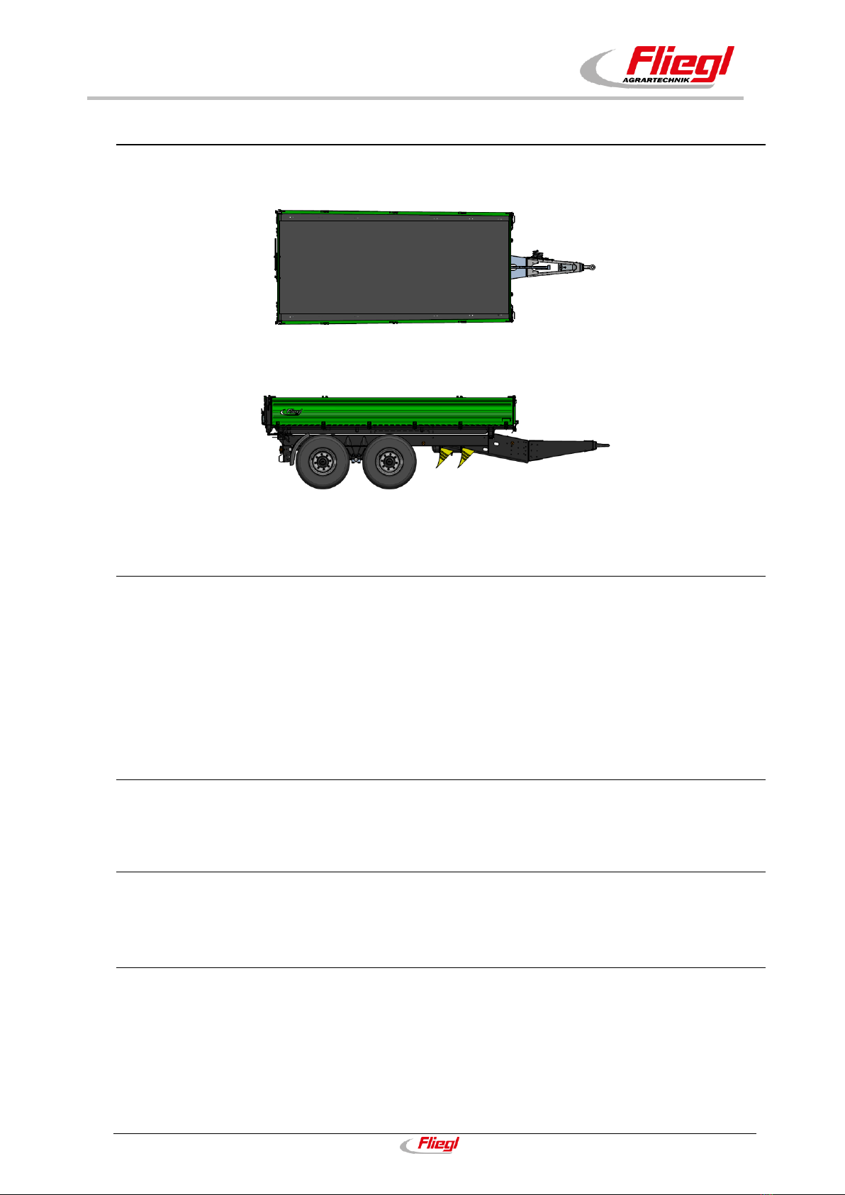
Top
Rear Front
Right side view
Fig. 2:Main view of the tandem three-way tipper (model may vary)
1.3 Illustrations used
Instructions and system responses
The steps to be taken by operating personnel are presented in the form of a (numbered) list.
These steps must be followed in the correct order. The system response to each operator action is
marked with an arrow. Example:
Operator action step 1
System response to operator action step 1
1.4 Cross references
Cross references to other points in the operating instructions appear in the text along with the relevant
chapter and subchapter or section.
1.5 Terminology: "trailer", "machine", "vehicle"
Within this document, the tandem three-way tipper is also referred to as the "trailer", "machine" or
"vehicle".
1.6 Figures
The figures in this document do not always depict the exact machine type.
The information relating to the figures always corresponds to the machine type described in this
document.
User instructions
14
1.7 Scope of the document
In addition to the standard models, B variants of the machine are also described in this document. Your
machine may deviate from this.
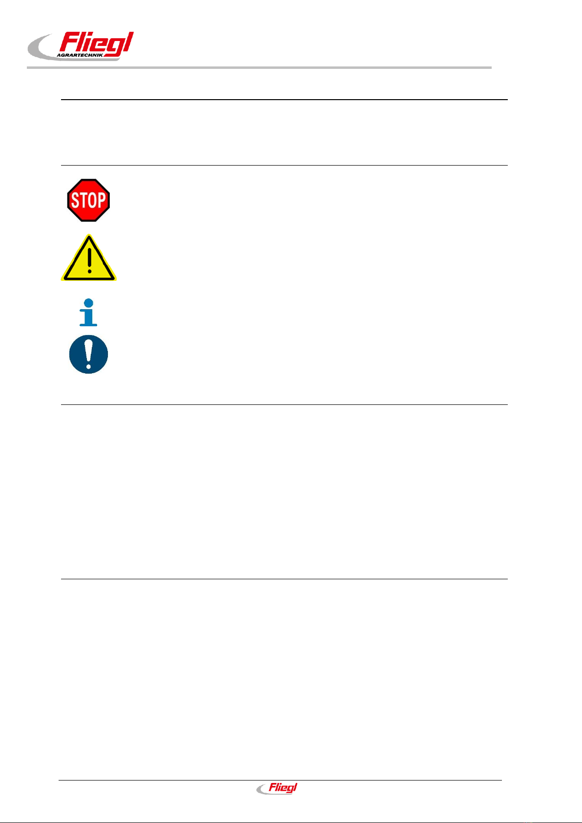
1.8 Presentation of safety instructions
Danger!
Imminent risk that will lead to serious bodily harm or death.
Warning!
Potentially hazardous situation that could lead to serious bodily harm or death.
Caution!
Potentially hazardous situation that could lead to minor bodily harm. Also warns
against potential damage to property.
Notice!
Potentially harmful situation in which the product or other property in its vicinity
could be damaged.
Important!
For usage instructions and other helpful information.
1.9 Liability and damages
The product must only be operated by persons who are familiar with the operating instructions, the
product and national laws, directives and regulations relating to health and safety at work as well as
accident prevention. We accept no liability for personal or material damage caused, or contributed to, by
untrained persons due to non-compliance with regulations regarding health and safety at work as well as
accident prevention.
Based on the specifications in these operating instructions, Fliegl Agrartechnik GmbH assumes no
liability for direct or consequential damage attributable to improper operation or maintenance. For your
own safety, you should only use original replacement parts and accessory products. Fliegl Agrartechnik
GmbH assumes no liability for the use of other products and any resulting damage. No claims for
modification of delivered products can be made on the basis of the information, images and descriptions
provided in this manual.
1.10 Duty to inform
These operating instructions are to be considered part of the tandem three-way tipper.
If the machine is passed on to another party by the customer, the operating instructions must also be
passed on and the party receiving the machine must be instructed regarding the regulations cited above.
Only the procedures described in these operating instructions are safe.
Read and observe the contents of chapter 2 Basic safety instructions before first using the
machine.
Before performing any work with the machine, always read and observe the contents of the
relevant sections of the operating instructions.
The operating instructions must be stored such that they are always on hand for the machine
user.

Safety instructions
15
2.Basic safety instructions
Failure to observe the safety instructions and warnings can pose a risk to
persons, property and the environment.
Non-compliance can also result in the loss of any claims for damage
compensation on the part of the customer.
When driving on public roads, be aware of the following:
When driving on public roads, the provisions of the country-specific registration regulations must be
observed.
The operator is personally responsible for the registration of the vehicle.
Lost permit documents can only be replaced by agreement with the administrative/regulatory authority
specified below. A duplicate of the permit documents will be given to the customer by the
administrative/regulatory authority.
A duplicate of the CoC document can be issued by the manufacturer.
Before driving on public roads:
- Before travelling on public roads, ensure that the maximum permissible dimensions,weights as
well as axle, drawbar and trailer loads dictated by EU or national law are not exceeded.
- The side panels must be closed.
- The tipper bridge must be lowered.
- The support gear must be completely raised.
- Lighting equipment must be connected.
- A functional check of the lighting equipment must be performed.
- For equipment with a connection for the tractor hydraulics, the hydraulic lines between the
towing vehicle and trailer must be disconnected or their actuation device locked.
- If the trailer is equipped with an overrun brake, the breakaway cable must be attached to the
tractor.
The controls of the on-board hydraulic system must be laid out so that visual contact with
the trailer can be maintained during operation.
Before the trailer is connected to the towing vehicle, its compatibility with tow
connection(s), hydraulic connections, permitted axle loads, etc. must be adapted to the
operating conditions and set accordingly.
Entering or remaining in the trailer is only permitted when it is stopped and the towing
vehicle is turned off.
Check the trailer after use every day for obvious damage and defects.
In the case of damage that affects safety, repair the trailer immediately.
In the event of any faults that affect safety, the trailer must be stopped immediately.
The trailer and the tractor must be secured against reactivation.
Changes to the trailer must only be carried out following consultation and with express
permission of the manufacturer.
Use only original replacement parts.
Follow the maintenance intervals stipulated in this manual.
In addition to this manual, the operating instructions included for third-party components
must be observed.
Note the permitted axle load, total weight and maximum speed.

Safety instructions
16
Notes on driving with the tandem three-way tipper
The handling characteristics of a towing vehicle are influenced by the coupled trailer.
Always adjust the vehicle speed to the local conditions.
Avoid sudden cornering when driving uphill and downhill as well as when crossing a
slope.
When driving uphill, use a low gear. Never change or disengage gears on a gradient.
When driving downhill / mountain passes, care must be taken not to overheat the
brakes. After long, hard braking and pass driving, they must let the brakes cool down.
Stop the towing vehicle immediately if a brake fault occurs.
Rectify any faults immediately.
There is a risk of tipping when driving on inclines.
The driving style must be adapted to the terrain and ground conditions.
The operator workstation is the driver's seat of the towing vehicle.
The tractor must be fitted with ballast weights in order to ensure steering and braking
capability (at least 20% of the vehicles empty weight on the front axle).
Carrying persons on the trailer is prohibited.
Climbing on and off safely
Careless behaviour can result in falling when climbing on and off the machine. Persons
climbing on to the machine without using the designated access points may slip, fall and suffer
serious injuries.
The safety of access points can be impaired by dirt and debris.
Always ensure that access points are clean and in working condition.
Never climb on or off the machine while it is moving.
Never jump off the machine.
Only climb on and off the machine via the access points specified in the operating
instructions.
Notes on coupling and uncoupling the tandem three-way tipper
There is an injury risk when coupling devices to the tractor.
When coupling, do not step between the trailer and the tractor while the tractor is
moving backwards.
Nobody must enter the area between the tractor and the trailer unless the vehicles
have been secured against rolling away with the parking brake and/or wheel chocks.
Release the parking brake before driving off.
(Turn the crank inward.)
Parking the tandem three-way tipper
Park the TDK on level, solid ground.
Secure the trailer to prevent it rolling away (with parking brake, wheel chocks).
On soft ground, the supporting mechanism's surface area must be increased by using
a suitable aid (e.g. a wood plank).
Extend the supporting mechanism.
Ensure that the machine is positioned securely before performing any adjustments,
repairs, maintenance or cleaning.

Safety instructions
17
Handling the supporting mechanism
Coupling the TDK
Couple the TDK to the tractor
(the coupling height can be adjusted via the supporting mechanism).
The load on the supporting mechanism can be reduced by operating the actuation
device.
Fully retract the supporting mechanism and then secure it if possible.
Uncoupling the TDK
The supporting mechanism can be extended by operating the actuation device.
Uncouple the TDK (the coupling height can be adjusted via the supporting
mechanism).
Disconnect the hydraulic and electrical lines as well as the brake system and uncouple
the vehicle.
The tractor is a weight-bearing element for tandem trailers.
Therefore, the trailer must only be set down on the supporting foot when it is empty.

Safety instructions
18
2.1 Designated use
The machine is constructed according to the EC Machinery Directive using the latest technology and in
accordance with the recognised safety regulations.
However, during use there is a risk to life and limb for the user or third party, or risk of damage to the
machine or other property.
The TDK must only be used as intended and when in good and safe working
condition.
Operational safety of the machine is guaranteed only if it is used as intended.
An unequally distributed load can cause damage to the vehicle, for which Fliegl Agrartechnik GmbH
shall assume no liability. To be used exclusively for transporting agricultural and forestry products
(e.g. grain of all kinds, fruit, vegetables, potatoes etc.)
Always use a signaller when reversing (as required by German road traffic regulations).
The machine is intended solely for agricultural use and must only be used if:
All safety equipment specified in the operating instruction is present and in the safety position
All safety instructions in the operating instructions are observed and complied with, including the
information in the chapter "Basic safety instructions" as well as the specific instructions in the
individual chapters
The operating instructions form part of the machine and must remain with the machine at all times.
The machine must only be operated following appropriate instruction and in strict compliance with these
operating instructions.
Any use of the machine not described in the operating instructions can result in serious injury or death
and may also lead to machine and property damage.
Unauthorised changes to the machine can have a negative impact on the machine properties or impair
its correct function. Unauthorised changes will therefore release the manufacturer from any resulting
liability.
Designated use also includes compliance with the operating, maintenance, cleaning and repair
instructions prescribed by the manufacturer.

Safety instructions
19
2.2 Reasonably foreseeable misuse
Any use other than the defined "designated use" or any use which exceeds this shall be defined as
misuse. The manufacturer/supplier accepts no liability for any resulting damages.
Misuse can be dangerous.
Examples of such misuse are:
Transporting persons
Exceeding the permissible total weight
Exceeding the permissible speed
Failure to observe safety stickers on the machine and safety information in the operating
instructions
Performing troubleshooting, adjustments, cleaning, repairs and maintenance contrary to the
specifications in the operating instruction
Unauthorised changes to the machine
Attachment of additional equipment that has not been authorised or approved
Use of non-original FLIEGL replacement parts
Transportation of broken glass, scrap steel, sharp-edged goods, aggressive materials, artificial
fertilizer, materials with a PH value higher than the neutral value
Caution when reversing:
Because the area behind the trailer cannot be seen, or can only be partially seen from the operator
workstation, a signaller is mandatory when reversing (as required by German road traffic regulations).
Modifications and changes
Any unauthorised modifications and changes to the machine (such as welding onto bearing parts)
will void all liabilities and the manufacturer's warranty.
Additions or modifications of any kind can affect the electro-magnetic behaviour of the machine.
Therefore, do not make any changes or add anything to the machine without consulting and receiving
written agreement from the manufacturer.
Replacement and wear parts and auxiliary materials
The use of replacement and wear parts or auxiliary materials from third parties can lead to dangers.
The manufacturer accepts no liability for damage resulting from the use of these parts.
Therefore, use only original parts or parts approved by the manufacturer.
This manual suits for next models
10
Table of contents
Other Fliegl Farm Equipment manuals


Popular Farm Equipment manuals by other brands

horsch
horsch Transformer 6 VF operating instructions

Agromehanika
Agromehanika AGS 2000 Series Instructions for use

Sulky
Sulky Isobus X Series Original instructions

GREAT PLAINS
GREAT PLAINS PL5500 installation manual

Yetter
Yetter GERMINATE UNIFORMITY 2940 Operator's manual

GREAT PLAINS
GREAT PLAINS Turbo Max 3500TM Assembly manual

Chore-Time
Chore-Time Auger Connector installation instructions

USC
USC AT500H DUAL PUMP STAND Troubleshooting

IMV
IMV AlphaVision instruction manual

Erskine Attachments
Erskine Attachments HB 18 Operator's manual

Unverferth
Unverferth BLU-JET SubTiller 4 manual

Foerster
Foerster TAK5-VH1-55 instruction manual


