Forster CalfRail User manual

Original Service Manual
CalfRail
Versions: IFS 6.10 / Feeder S 2.00
CRS2-IF1-WH
June 29, 2017

2 Table of contents
Table of contents
1. Introduction . . . . . . . . . . . . . . . . . . . . . . . . . . . . . . . . . . . . . . . . . . . . . . . . . . . . . . . . . . . . . . . . . 5
1.1 Overview of the CalfRail . . . . . . . . . . . . . . . . . . . . . . . . . . . . . . . . . . . . . . . . . . . . . . . . . . . 6
1.1.1 CalfRail viewed from the right. . . . . . . . . . . . . . . . . . . . . . . . . . . . . . . . . . . . . . . . . 6
1.1.2 Interior view . . . . . . . . . . . . . . . . . . . . . . . . . . . . . . . . . . . . . . . . . . . . . . . . . . . . . . 7
1.1.3 Front view . . . . . . . . . . . . . . . . . . . . . . . . . . . . . . . . . . . . . . . . . . . . . . . . . . . . . . . . 8
1.1.4 Name plate . . . . . . . . . . . . . . . . . . . . . . . . . . . . . . . . . . . . . . . . . . . . . . . . . . . . . . . 9
1.1.5 Supply line . . . . . . . . . . . . . . . . . . . . . . . . . . . . . . . . . . . . . . . . . . . . . . . . . . . . . . 10
1.1.6 Return valve . . . . . . . . . . . . . . . . . . . . . . . . . . . . . . . . . . . . . . . . . . . . . . . . . . . . . 10
1.1.7 Heating system . . . . . . . . . . . . . . . . . . . . . . . . . . . . . . . . . . . . . . . . . . . . . . . . . . . 11
1.2 Technical data . . . . . . . . . . . . . . . . . . . . . . . . . . . . . . . . . . . . . . . . . . . . . . . . . . . . . . . . . . 13
1.2.1 Electrical connection. . . . . . . . . . . . . . . . . . . . . . . . . . . . . . . . . . . . . . . . . . . . . . . 13
1.2.2 Dimensions . . . . . . . . . . . . . . . . . . . . . . . . . . . . . . . . . . . . . . . . . . . . . . . . . . . . . . 14
1.2.3 Weight. . . . . . . . . . . . . . . . . . . . . . . . . . . . . . . . . . . . . . . . . . . . . . . . . . . . . . . . . . 14
1.2.4 Number of feeding stations and animals . . . . . . . . . . . . . . . . . . . . . . . . . . . . . . . 14
1.2.5 Installation requirements. . . . . . . . . . . . . . . . . . . . . . . . . . . . . . . . . . . . . . . . . . . . 14
1.3 Disposal . . . . . . . . . . . . . . . . . . . . . . . . . . . . . . . . . . . . . . . . . . . . . . . . . . . . . . . . . . . . . . 16
1.4 Manufacturer's contact details . . . . . . . . . . . . . . . . . . . . . . . . . . . . . . . . . . . . . . . . . . . . . 16
2. Important safety instructions. . . . . . . . . . . . . . . . . . . . . . . . . . . . . . . . . . . . . . . . . . . . . . . . . . 17
2.1 Intended use . . . . . . . . . . . . . . . . . . . . . . . . . . . . . . . . . . . . . . . . . . . . . . . . . . . . . . . . . . . 17
2.2 Required qualifications . . . . . . . . . . . . . . . . . . . . . . . . . . . . . . . . . . . . . . . . . . . . . . . . . . . 17
2.3 Residual risks . . . . . . . . . . . . . . . . . . . . . . . . . . . . . . . . . . . . . . . . . . . . . . . . . . . . . . . . . . 17
2.4 How am I warned of hazards? . . . . . . . . . . . . . . . . . . . . . . . . . . . . . . . . . . . . . . . . . . . . . 18
2.4.1 What are the components of a hazard description? . . . . . . . . . . . . . . . . . . . . . . . 19
2.4.2 Potentially fatal hazards or health hazards. . . . . . . . . . . . . . . . . . . . . . . . . . . . . . 19
2.4.3 Material damage . . . . . . . . . . . . . . . . . . . . . . . . . . . . . . . . . . . . . . . . . . . . . . . . . . 19
2.5 Safety signs . . . . . . . . . . . . . . . . . . . . . . . . . . . . . . . . . . . . . . . . . . . . . . . . . . . . . . . . . . . 20
2.5.1 Warning signs on the machine . . . . . . . . . . . . . . . . . . . . . . . . . . . . . . . . . . . . . . . 20
2.5.2 Safety devices . . . . . . . . . . . . . . . . . . . . . . . . . . . . . . . . . . . . . . . . . . . . . . . . . . . 22
3. Commissioning . . . . . . . . . . . . . . . . . . . . . . . . . . . . . . . . . . . . . . . . . . . . . . . . . . . . . . . . . . . . . 24
3.1 Electrical connection provided by the customer . . . . . . . . . . . . . . . . . . . . . . . . . . . . . . . . 24
3.2 Hanging the running rail . . . . . . . . . . . . . . . . . . . . . . . . . . . . . . . . . . . . . . . . . . . . . . . . . .24
3.3 Mounting the CalfRail . . . . . . . . . . . . . . . . . . . . . . . . . . . . . . . . . . . . . . . . . . . . . . . . . . . . 26
3.4 Connecting the CAN bus and power. . . . . . . . . . . . . . . . . . . . . . . . . . . . . . . . . . . . . . . . . 28
3.5 Run and connect supply line. . . . . . . . . . . . . . . . . . . . . . . . . . . . . . . . . . . . . . . . . . . . . . . 30
3.6 Activating the heating system . . . . . . . . . . . . . . . . . . . . . . . . . . . . . . . . . . . . . . . . . . . . . . 31
3.7 Inserting the servopump hose. . . . . . . . . . . . . . . . . . . . . . . . . . . . . . . . . . . . . . . . . . . . . . 32
3.8 Attaching the magnets for the stopping positions . . . . . . . . . . . . . . . . . . . . . . . . . . . . . . . 33
3.9 Activating the CalfRail. . . . . . . . . . . . . . . . . . . . . . . . . . . . . . . . . . . . . . . . . . . . . . . . . . . . 34
3.10 Testing the CalfRail . . . . . . . . . . . . . . . . . . . . . . . . . . . . . . . . . . . . . . . . . . . . . . . . . . . . . . 35
3.11 Calibration. . . . . . . . . . . . . . . . . . . . . . . . . . . . . . . . . . . . . . . . . . . . . . . . . . . . . . . . . . . . . 37
3.11.1 Calibration of the hose pump . . . . . . . . . . . . . . . . . . . . . . . . . . . . . . . . . . . . . . . . 37

Table of contents 3
3.11.2 Automatic calibration . . . . . . . . . . . . . . . . . . . . . . . . . . . . . . . . . . . . . . . . . . . . . . 37
3.12 Cleaning the CalfRail . . . . . . . . . . . . . . . . . . . . . . . . . . . . . . . . . . . . . . . . . . . . . . . . . . . . 38
4. Transmitter and animal management . . . . . . . . . . . . . . . . . . . . . . . . . . . . . . . . . . . . . . . . . . . 39
4.1 Manual registration of animals . . . . . . . . . . . . . . . . . . . . . . . . . . . . . . . . . . . . . . . . . . . . . 39
4.2 Canceling animals or animal groups. . . . . . . . . . . . . . . . . . . . . . . . . . . . . . . . . . . . . . . . . 41
4.2.1 Canceling individual animals . . . . . . . . . . . . . . . . . . . . . . . . . . . . . . . . . . . . . . . . 41
4.2.2 Canceling a group. . . . . . . . . . . . . . . . . . . . . . . . . . . . . . . . . . . . . . . . . . . . . . . . . 42
4.2.3 Canceling weaned animals. . . . . . . . . . . . . . . . . . . . . . . . . . . . . . . . . . . . . . . . . . 42
4.3 Changing the registration of animals . . . . . . . . . . . . . . . . . . . . . . . . . . . . . . . . . . . . . . . . 42
4.4 Changing the box for the CalfRail . . . . . . . . . . . . . . . . . . . . . . . . . . . . . . . . . . . . . . . . . . . 43
4.4.1 Box/transmitter present. . . . . . . . . . . . . . . . . . . . . . . . . . . . . . . . . . . . . . . . . . . . . 43
4.4.2 Resetting a transmitter . . . . . . . . . . . . . . . . . . . . . . . . . . . . . . . . . . . . . . . . . . . . . 43
5. Feeding . . . . . . . . . . . . . . . . . . . . . . . . . . . . . . . . . . . . . . . . . . . . . . . . . . . . . . . . . . . . . . . . . . . 45
5.1 Feeding plans . . . . . . . . . . . . . . . . . . . . . . . . . . . . . . . . . . . . . . . . . . . . . . . . . . . . . . . . . . 45
5.2 Feeding times . . . . . . . . . . . . . . . . . . . . . . . . . . . . . . . . . . . . . . . . . . . . . . . . . . . . . . . . . . 46
5.3 Feeding of additives . . . . . . . . . . . . . . . . . . . . . . . . . . . . . . . . . . . . . . . . . . . . . . . . . . . . . 46
5.4 Plan for maximum speed . . . . . . . . . . . . . . . . . . . . . . . . . . . . . . . . . . . . . . . . . . . . . . . . . 47
5.5 Waiting times . . . . . . . . . . . . . . . . . . . . . . . . . . . . . . . . . . . . . . . . . . . . . . . . . . . . . . . . . . 48
5.6 Monitoring the first feeding . . . . . . . . . . . . . . . . . . . . . . . . . . . . . . . . . . . . . . . . . . . . . . . .48
5.7 Starting the CalfRail manually. . . . . . . . . . . . . . . . . . . . . . . . . . . . . . . . . . . . . . . . . . . . . . 49
5.7.1 Start feeding . . . . . . . . . . . . . . . . . . . . . . . . . . . . . . . . . . . . . . . . . . . . . . . . . . . . . 49
5.7.2 Move feeding forward. . . . . . . . . . . . . . . . . . . . . . . . . . . . . . . . . . . . . . . . . . . . . . 50
5.7.3 Stop feeding . . . . . . . . . . . . . . . . . . . . . . . . . . . . . . . . . . . . . . . . . . . . . . . . . . . . . 50
6. Maintenance work. . . . . . . . . . . . . . . . . . . . . . . . . . . . . . . . . . . . . . . . . . . . . . . . . . . . . . . . . . . 51
6.1 Important safety instructions . . . . . . . . . . . . . . . . . . . . . . . . . . . . . . . . . . . . . . . . . . . . . . . 51
6.2 Annual care and maintenance intervals . . . . . . . . . . . . . . . . . . . . . . . . . . . . . . . . . . . . . . 52
6.2.1 Replacing the servopump hose . . . . . . . . . . . . . . . . . . . . . . . . . . . . . . . . . . . . . . 52
6.2.2 Replacing the hose for the teat cleaner . . . . . . . . . . . . . . . . . . . . . . . . . . . . . . . . 53
6.2.3 Replacing the suction hose in the supply line. . . . . . . . . . . . . . . . . . . . . . . . . . . . 54
6.2.4 Cleaning the return valve . . . . . . . . . . . . . . . . . . . . . . . . . . . . . . . . . . . . . . . . . . . 55
6.2.5 Cleaning the suction sensor . . . . . . . . . . . . . . . . . . . . . . . . . . . . . . . . . . . . . . . . . 56
6.2.6 Cleaning the heating system housing. . . . . . . . . . . . . . . . . . . . . . . . . . . . . . . . . . 56
6.2.7 Cleaning the water filter . . . . . . . . . . . . . . . . . . . . . . . . . . . . . . . . . . . . . . . . . . . . 57
7. Shutdown and recommissioning. . . . . . . . . . . . . . . . . . . . . . . . . . . . . . . . . . . . . . . . . . . . . . . 59
7.1 Shutdown . . . . . . . . . . . . . . . . . . . . . . . . . . . . . . . . . . . . . . . . . . . . . . . . . . . . . . . . . . . . . 59
7.2 Permanent shutdown . . . . . . . . . . . . . . . . . . . . . . . . . . . . . . . . . . . . . . . . . . . . . . . . . . . . 62
7.3 Recommissioning after a long-term shutdown . . . . . . . . . . . . . . . . . . . . . . . . . . . . . . . . . 62
8. Faults and warnings . . . . . . . . . . . . . . . . . . . . . . . . . . . . . . . . . . . . . . . . . . . . . . . . . . . . . . . . . 65
8.1 Warnings. . . . . . . . . . . . . . . . . . . . . . . . . . . . . . . . . . . . . . . . . . . . . . . . . . . . . . . . . . . . . . 65
8.1.1 CalfRail . . . . . . . . . . . . . . . . . . . . . . . . . . . . . . . . . . . . . . . . . . . . . . . . . . . . . . . . . 65
8.1.2 CalfRail pivot arm . . . . . . . . . . . . . . . . . . . . . . . . . . . . . . . . . . . . . . . . . . . . . . . . . 66
8.1.3 CalfRail travel to parking. . . . . . . . . . . . . . . . . . . . . . . . . . . . . . . . . . . . . . . . . . . . 66

4 Table of contents
8.1.4 CalfRail travel to box. . . . . . . . . . . . . . . . . . . . . . . . . . . . . . . . . . . . . . . . . . . . . . . 66
8.1.5 CR feeding/flushing . . . . . . . . . . . . . . . . . . . . . . . . . . . . . . . . . . . . . . . . . . . . . . . 67
8.1.6 Automatic calibration . . . . . . . . . . . . . . . . . . . . . . . . . . . . . . . . . . . . . . . . . . . . . . 67
8.1.7 Feed deviation . . . . . . . . . . . . . . . . . . . . . . . . . . . . . . . . . . . . . . . . . . . . . . . . . . . 67
8.1.8 Heating system water shortage . . . . . . . . . . . . . . . . . . . . . . . . . . . . . . . . . . . . . . 67
8.1.9 Heating system temperature. . . . . . . . . . . . . . . . . . . . . . . . . . . . . . . . . . . . . . . . . 68
8.1.10 Heating sensor . . . . . . . . . . . . . . . . . . . . . . . . . . . . . . . . . . . . . . . . . . . . . . . . . . . 69
8.1.11 Heating system pump . . . . . . . . . . . . . . . . . . . . . . . . . . . . . . . . . . . . . . . . . . . . . . 69
8.1.12 CR water heating system . . . . . . . . . . . . . . . . . . . . . . . . . . . . . . . . . . . . . . . . . . . 69
8.2 Diagnosis . . . . . . . . . . . . . . . . . . . . . . . . . . . . . . . . . . . . . . . . . . . . . . . . . . . . . . . . . . . . . 70
8.2.1 Checking stations . . . . . . . . . . . . . . . . . . . . . . . . . . . . . . . . . . . . . . . . . . . . . . . . . 70
9. Appendix . . . . . . . . . . . . . . . . . . . . . . . . . . . . . . . . . . . . . . . . . . . . . . . . . . . . . . . . . . . . . . . . . . 72
9.1 Initial commissioning checklist . . . . . . . . . . . . . . . . . . . . . . . . . . . . . . . . . . . . . . . . . . . . . 72
9.2 Materials list . . . . . . . . . . . . . . . . . . . . . . . . . . . . . . . . . . . . . . . . . . . . . . . . . . . . . . . . . . . 73
9.3 Care and Maintenance schedule / routine work . . . . . . . . . . . . . . . . . . . . . . . . . . . . . . . . 74
9.3.1 Important safety instructions. . . . . . . . . . . . . . . . . . . . . . . . . . . . . . . . . . . . . . . . . 74
9.3.2 Maintenance intervals and activities. . . . . . . . . . . . . . . . . . . . . . . . . . . . . . . . . . . 75
9.4 Shutdown checklist . . . . . . . . . . . . . . . . . . . . . . . . . . . . . . . . . . . . . . . . . . . . . . . . . . . . . . 76
9.5 Checking components for compliance with national regulations . . . . . . . . . . . . . . . . . . . 76
Index. . . . . . . . . . . . . . . . . . . . . . . . . . . . . . . . . . . . . . . . . . . . . . . . . . . . . . . . . . . . . . . . . . . . . . 77

Introduction 5
1. Introduction
This manual enables you to commission the CalfRail safely as intended.
• The end user must provide you with the operating manual of the CalfRail and the safety data
sheets for the cleaning agents.
• Carefully read all operating instructions and safety data sheets before initial commissioning
or recommissioning of the CalfRail.
• Observe all of the warnings and safety instructions in this operating manual at all times.
• The CalfRail is connected to an automatic feeder. You must also comply with the separate
operating manuals, safety instructions and warnings for the automatic feeder.

6 Introduction
1.1 Overview of the CalfRail
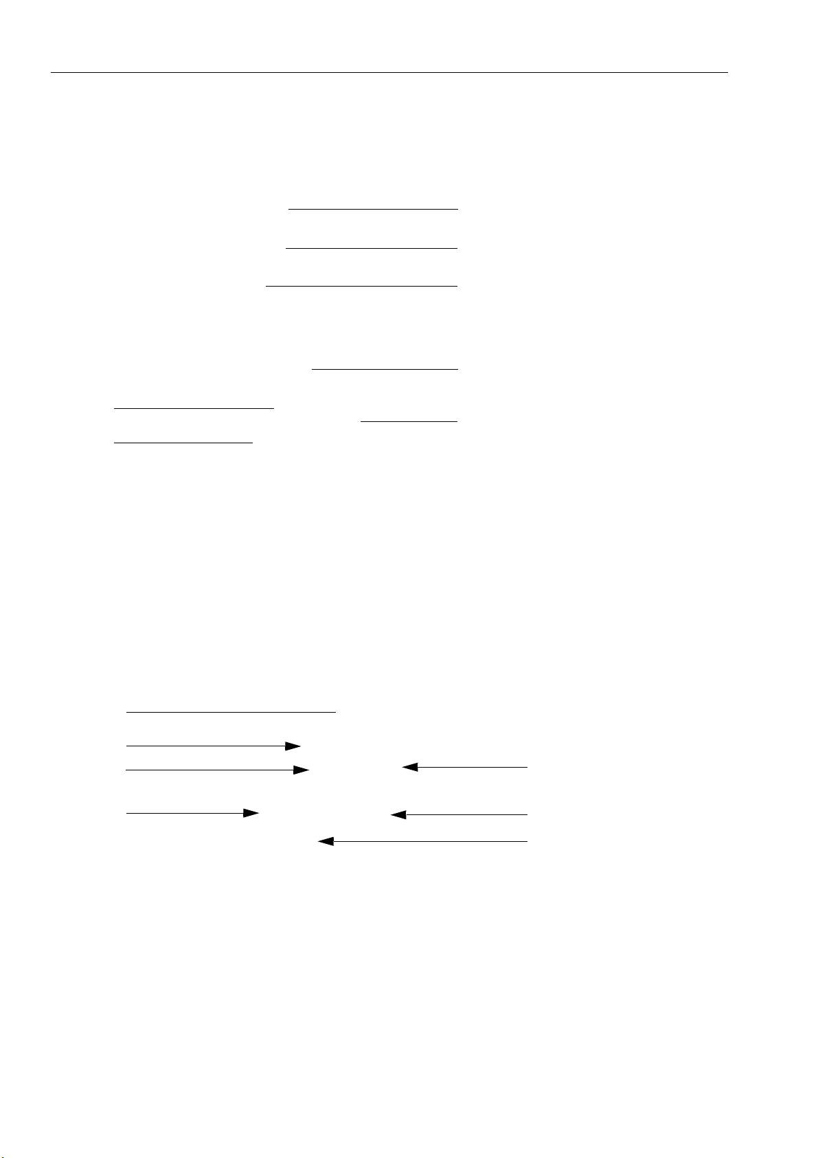
1.1.1 CalfRail viewed from the right
1 Service door
2 Screws to adjust teat height
3 CalfRail unit
4 Service opening for suction sensor
5Teat
6 AFeed button with entitlement LED
7 Supply line
4
1
3
5
7
6
Direction of travel
2

Introduction 7
1.1.2 Interior view
1 Servopump
2 Pump for teat cleaning (optional)
3 Connectors for hose group
1
2
3

8 Introduction
1.1.3 Front view
1Rail
2 Drive carriage
3 Quick release
4 LED light strip
5 Continue button
6 Feed button with entitlement LED
7 Teat cleaner (optional)
8 Return valve (internal)
Continue button
If during feeding the CalfRail is in front of a box and this button is pressed, the CalfRail moves
on to the next box.
2
3
4
5
6
7
8
1

Introduction 9
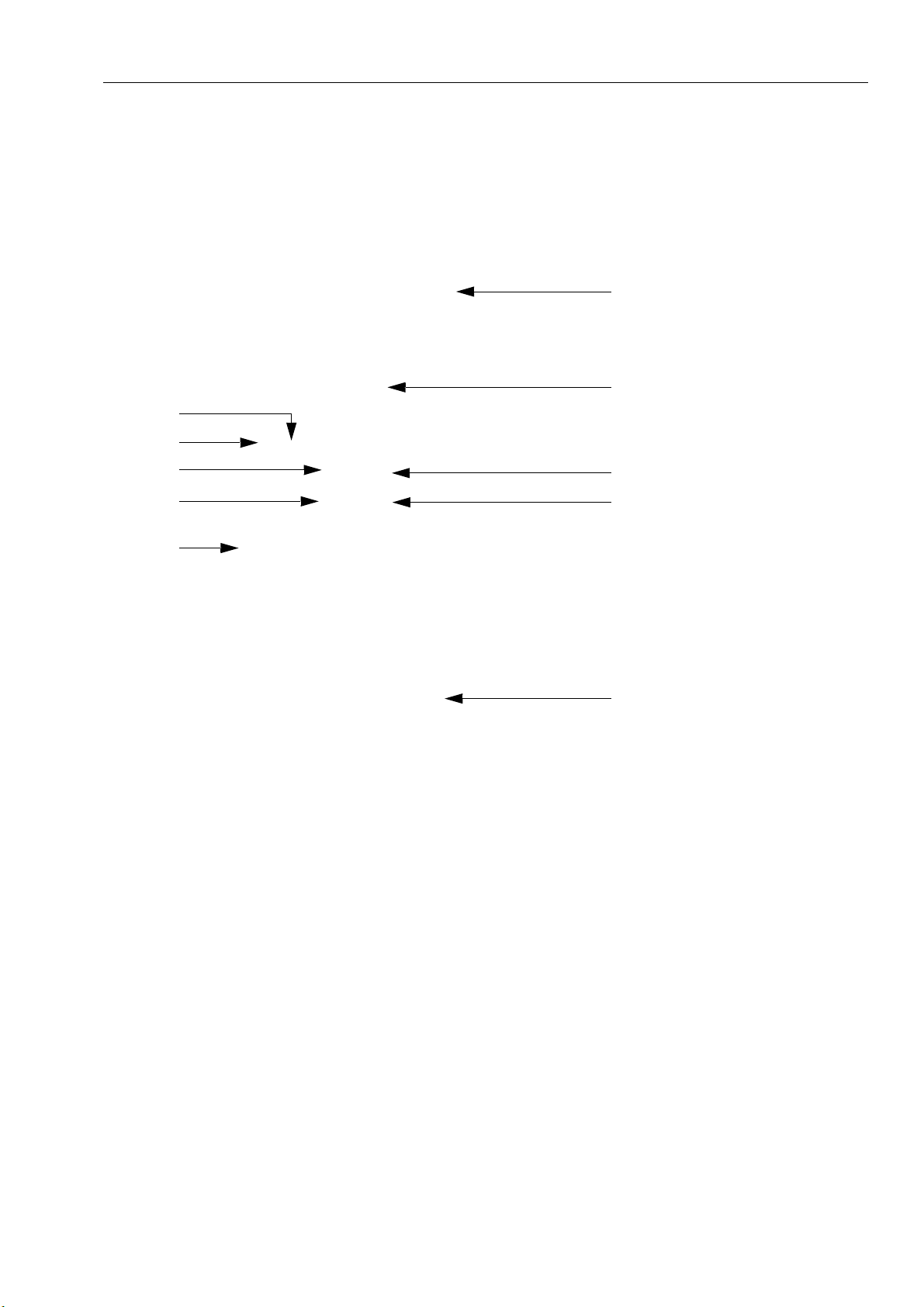
Feed button
The feed button activates the servopump. The servopump makes it easier for the animals to
become accustomed to automatic feed consumption and encourages weak calves to consume
feed. The feed button has an integrated Entitlement LED:
• LED lights up: The calf has a feed entitlement.
• LED flashes slowly: The calf has a feed entitlement < 0.5 liters.
• LED flashes rapidly: The calf has no feed entitlement.
1.1.4 Name plate
There is a name plate on the left-hand exterior side of the CalfRail and on the rear of the control
box and there is a component name plate on the rear of the heating system. They provide in-
formation about the manufacturer, type and number of the CalfRail, information for connecting
the feeder to the mains as well as the certifications of the CalfRail. An example of a name plate
is shown below.
1 Name and address of the manufacturer
2 Type and number of the CalfRail
3 Information for connection to the mains
4 Certifications of the CalfRail
1
2
3
4
10 Introduction
1.1.5 Supply line
1 CAN bus cable (violet)
2 CalfRail power supply (gray)
3 Suction hose return line ø7 mm (without marking)
4 Heating system return line (2 x, blue)
5 Teat cleaner ø5 mm (optional)
6 Heating system feed line (blue)
7 Suction hose (red)
1.1.6 Return valve
The return valve is located inside the pivot arm.
1 Teat cleaner (optional)
2 Return valve
3 Heating system return line (2 x, blue)
4 Suction hose return line (without marking)
5 Suction hose (red)
6 Heating system feed line (blue)
7 Power supply connection for return valve (gray)
1
2
3
6
75
4
1
2
3
6
5
4
7
Introduction 11
1.1.7 Heating system
Front view
1 Expansion vessel
2 Hose holder
3 Port for return line
4 Port for feed line
5 Temperature sensor
6 Control box cover (not shown)
7 Port for CAN bus cable (CalfRail 1)
8 Port for CAN power supply (CalfRail 1)
9 Port for other CAN participants (e.g. IFS)
10Port for CAN bus cable to automatic feeder
1
2
3
4
8
9
10
6
5
7

12 Introduction
Single unit rear view
1 Expansion vessel
2 Component name plate
3 Main switch
4 Mains connection
5 Filter
3
4
5
2
1
Introduction 13
Double unit rear view
1 Expansion vessel
2 Component name plate
3 Main switch
4 Mains adapter for second CalfRail
5 Mains connection
6 Filter
1.2 Technical data
1.2.1 Electrical connection
Note: The electrical connection specifications of the CalfRail can be found on the name plate
on the left-hand side of the CalfRail unit and on the component name plate of the heating sys-
tem.
2
3
5
6
4
1

14 Introduction
1.2.2 Dimensions
1.2.3 Weight
CalfRail unit: approx. 40 kg.
Water heating system: approx. 35 kg.
1.2.4 Number of feeding stations and animals
1.2.5 Installation requirements
1.2.5.1 Structural integrity of the carrier system
The hanger elements for the rails on the carrier system must be designed so as to accommo-
date both the vertical and horizontal loads in the rail direction and perpendicular to the rail di-
rection.
CalfRail/automatic feeder Calves/CalfRail Calves/side
Max. 2 Max. 32 Max. 16

Introduction 15
In planning the carrier system, the following hanging loads deriving from the CalfRail system
must be taken into account for the carriers exposed to the greatest load:
• Vg,k = 1.0 kN (vertical hanging load resulting from the dead load)
• Vp,k = 0.10 kN (vertical hanging load resulting from the payload)
• HL,k = 0.05 kN (horizontal load in rail direction resulting from the inertial forces)
• HQ,k = 0.06 kN (horizontal load perpendicular to rail direction resulting from the transverse
pull)
Note: All hanging loads include the dynamic increase factors!
The specified values apply subject to the following conditions:
• Spacing of rail fasteners < 3.0 m
• Spacing of carriers of the carrier system on which the rail is hung < 6.0 m
1.2.5.2 Running rail
• The running rail should be suspended at a height of 2.2 meters (measured from the calf floor
level to the running rail).
• The distance between the suspension points for the running rail may not be more than 3 me-
ters.
• The running rail must be able to carry the weight of the CalfRail unit (40 kg).
• The rail system must be installed without any inclination or tilt.
• A roof over the running rail is recommended.
• The maximum length of the hose group from the automatic feeder to the CalfRail is 30 me-
ters for each CalfRail.
• The running rails may not be welded to the carrier system.
Note: The carrier system must be configured to suit.
1.2.5.3 Igloo/Calf box
• The calf boxes should have only a single central opening.
• This enables easy installation as opposite-facing boxes can be set up as mirror images
of one another
• Off-center openings result in offset boxes with an individual orientation, since the teat
must always come to rest in the middle of the opening. This can mean longer rail and
hose lengths
• The distance from the rail to the calf box should be 0.7 - 1 meter. Therefore the feeding alley
should be set up as follows:
• At least 1 meter distance from the building wall to the calf box;
• Minimum of 1.4 meters from calf box to calf box, up to a maximum of 2.0 meters.
1.2.5.4 Automatic feeder
As a prerequisite for operating the CalfRail, the following must be present for the installation:
• Automatic feeder VARIO smart (TA*-VS*) (with current software version)
• Power outlet

16 Introduction
• Water connection
• Drain for flushing water
• 1 x power outlet for the CalfRail
• 2 x power outlets as backup near the automatic feeder
• Ideally, a drain for flushing water at the parking position
• Space for parking position, at least 0.6 meters wide and 1.5 to 3.0 meters long
1.3 Disposal
All components, liquids and solids must be disposed of in compliance with the applicable official
regulations for proper waste recycling and disposal in your country. Also comply with the corre-
sponding safety data sheets.
1.4 Manufacturer's contact details
Please contact us if you have any questions about our products or require technical support!
When you contact us, always specify the serial number of your CalfRail. The serial number is
located on the name plate on the left side of your CalfRail unit.
Also specify the device type and the program version of your automatic feeder and your CalfRail
so that you can obtain service tailored to your automatic feeder. The device number and model
are located on the name plate on the left of the housing of the automatic feeder and the CalfRail
unit.
You can call up the program version via your hand-held terminal. The relevant menu item can
be found under > Diagnosis > Version > Peripherals > CalfRail or CR water heating sys-
tem.
You can note the device type, serial number and program version in the fields provided.
Device type:
Serial number:
CalfRail program version:
Water heating system program version:
Our contact details:
Förster-Technik GmbH
Gerwigstrasse 25
78234 Engen, Germany
Phone: +49/ (0)7733/ 9406- 0
Fax: +49/ (0)7733/ 9406- 99
www.foerster-technik.de

Important safety instructions 17
2. Important safety instructions
You will learn about the following in this section:
• The hazards presented by the CalfRail and how to avoid those hazards.
• The safety signs on the CalfRail and what they mean.
• How to install the CalfRail safely.
The CalfRail has been designed in accordance with accepted rules of engineering and ap-
proved safety standards. Hazards and adverse effects may nevertheless arise during operation.
These hazards are indicated by the warning signs directly on the CalfRail as well as the warning
messages in this service manual.
2.1 Intended use
The CalfRail is only intended for the distribution, provision, delivery and dispensing of animal
feed in liquid form for the Vario automatic calf feeder.
2.2 Required qualifications
Only trained service technicians are authorized to install the CalfRail, put it into service and sub-
ject it to maintenance and repairs.
Service technicians are specialists with appropriate qualifications. They are able to assess the
work assigned to them and detect potential risks on the basis of their technical training as well
as their knowledge of the relevant standards. They have knowledge of relevant accident pre-
vention regulations, generally accepted safety regulations and country-specific standards and
provisions.
2.3 Residual risks
Hazards to life and health caused by the CalfRail:
WARNING!
Hazards due to electrical power
The CalfRail is operated with electrical power.
► You must observe the general precautions for handling electrical devices.
• Read the operating manual before commissioning the CalfRail.
• Keep children away from the CalfRail.
• Do not touch any moving parts of the CalfRail, such as the drive motor.
• Use only original replacement parts made by the manufacturer.
• Always disconnect the mains plug before performing any maintenance or cleaning on the
CalfRail.
• If you are operating the CalfRail outside of enclosed spaces, you must protect it against rain
and moisture, for example with a roof.

18 Important safety instructions
• The following specific hazards are associated with the CalfRail's electrical system:
•Electric shock. If there is an electrical or voltage breakdown, electric current will flow
through parts of the CalfRail that are normally isolated. Touching the unit can cause a
fatal electric shock. The CalfRail must be checked regularly for electrical safety in com-
pliance with national regulations (repeated inspection) and you must install a 30mA re-
sidual current device (RCD).
•Short circuit, indirect contact. A short circuit can result in currents that are many times
greater than the operating current. Touching the unit can cause a fatal electric shock. In-
stall fuse protection (provided by the customer) with the rating specified on the name
plate and a residual current device (RCD) of 30 mA in compliance with local regulations.
•Harsh environmental conditions. In agricultural operations, water hoses or pressure
washers are often used to clean areas. This can damage the CalfRail. Never spray-wash
the CalfRail.
•Risk of becoming pulled in or trapped. The CalfRail unit is attached to the carriage by
means of a slewing ring. In order to prevent injuries to fingers, do not touch the CalfRail while
it is slewing.
•Chemical burns. The cleaning agent used to clean the CalfRail contains caustic substanc-
es. These substances can cause serious injuries to the hands or eyes. Avoid direct contact
with the cleaning agent and always wear chemical-resistant protective gloves and safety
glasses when using the cleaning agent.
Material damage caused by the CalfRail
The CalfRail can cause the following types of material damage:
•Infection. Improper cleaning or incorrect operation can result in calves becoming infected
by pathogens from the CalfRail. This can result in medical costs or death of calves.
•Corrosion. Improper cleaning or maintenance can result in the CalfRail ceasing to function
correctly.
2.4 How am I warned of hazards?
Hazards are indicated directly on the CalfRail by safety signs (warning signs, instruction and
prohibition notices), and in the operating manual by specially marked hazard descriptions.
The warnings for hazards that can cause death or injury to people are given greater prominence
that those for material damage, for example through the colors, hazard words or symbols used.
Safety signs are an important element of the overall CalfRail safety concept. They provide warn-
ings about hazards and explain how to avoid them.
Make sure that all the specified safety signs are fitted to your CalfRail and that they are in a
legible condition. If the safety signs are difficult to read, replace them immediately. New safety
signs are available from Förster-Technik GmbH.
Important safety instructions 19
2.4.1 What are the components of a hazard description?
A hazard description always consists of the following elements:
• Hazard word (danger, warning, caution, attention)
• Type of hazard (what can happen?)
• Location of hazard (where can it happen?)
• Actions necessary for preventing the hazard (what should I do?).
2.4.2 Potentially fatal hazards or health hazards
A hazard symbol indicates the risk of fatal injury or detrimental effects on health. The words and
symbols differ according to the severity and the likelihood of occurrence: (Warning triangle
with exclamation mark) and the following hazard words:
DANGER!
The word DANGER indicates an immediate danger that can cause loss of life or injury.
Warning signs on the CalfRail and in the operating manual: DANGER (white font on red back-
ground).
WARNING!
The word WARNING indicates a potentially dangerous situation that can result in loss of
life or severe injury.
Warning signs on the CalfRail and in the operating manual: WARNING (white font on orange
background).
CAUTION!
The word CAUTION indicates a potentially dangerous situation that can result in minor
injuries.
Warning signs on the CalfRail and in the operating manual: CAUTION (white font on yellow
background).
2.4.3 Material damage
The word Attention warns you about the risk of material damage. The CalfRail or an object in
its vicinity, such as a calf, can be damaged.
NOTICE!
The word ATTENTION warns you about the risk of material damage. The CalfRail or an
object in its vicinity, such as a calf, can be damaged.
Prohibitory signs on the CalfRail: A pictogram with a red line through it in a white circle with a
red border indicates what you may not do.
Operating manual: white font on a blue background.

20 Important safety instructions
2.5 Safety signs
Different safety labels are attached at the hazardous points on the CalfRail. Warning signs, pro-
hibition and instruction notices.
What are warning signs?
Warning signs consist of:
• A pictogram in a yellow triangle illustrating the potential hazard.
What are prohibitory signs?
Prohibitory signs have a pictogram of the prohibited action in a red circle with a line
through it. See the adjacent example. They graphically depict the prohibited ac-
tion. In this example, the hose with a line through it means that you may not use
high-pressure cleaners.
What are instruction notices?
Instruction notices show a pictogram of what you are being instructed to do in a
blue circle. They illustrate what you have to do. In the example, the pictogram
means that you must always disconnect the plug first.
Other signs
Grounding symbol. This symbol is placed in the locations where you must perform
potential equalization.
2.5.1 Warning signs on the machine
Danger of death by electric shock
Beware of hot fluids!
Table of contents
Other Forster Farm Equipment manuals


Popular Farm Equipment manuals by other brands

Schaffert
Schaffert Rebounder Mounting instructions

Stocks AG
Stocks AG Fan Jet Pro Plus 65 Original Operating Manual and parts list

Cumberland
Cumberland Integra Feed-Link Installation and operation manual

BROWN
BROWN BDHP-1250 Owner's/operator's manual

Molon
Molon BCS operating instructions

Vaderstad
Vaderstad Rapid Series instructions


