Flight Deck FlightDeck SC-6502 Operating instructions

SI-7AP1E
SERVICE INSTRUCTIONS
Cycle Computer
SC-6502 / SC-6501/ SC-M500
t

Be careful not to pay excessive
attention to the computer data while
riding, otherwise you might have an
accident.
NOTE;
* The all clear (AC) button is used to clear the main unit memory.
* Never disassemble the main unit, as it cannot be reassembled.
* The main unit is fully waterproofed to withstand wet weather
conditions; however, do not deliberately place it into water.
* Avoid leaving the main unit exposed to extremely hot weather
conditions.
* Handle the main unit carefully, and avoid subjecting it to any shocks.
* Do not use thinner or other solvents to clean parts such as the main
unit and sensor, as they may dissolve the part casings.
* To clean these parts, wipe them with a cloth soaked in a weak mixture
of neutral detergent and water.
* If using the SM-6501/M/MD together with an LED lamp from another
manufacturer, the speed measurement function may not work correctly.
If using an LED lamp from another manufacturer, it is recommended
that you use the SM-6500-RS.
Specifications
Meter
Bracket/Sensor unit
SC-6501 / SC-M500SC-6502
SM-6501 SM-6501-MD
STI lever
ST-7700-C
ST- 6510
ST-5500-CA
ST- 4400
ST- 3300/3303
SM-SC70
ST-7800
ST- M510
SL-M510
SM-6501-M
ST-M952 SL-M952
ST-M750 SL-M750
ST-M570 SL-M570
1. Display Modes
“Current speed” and “Gear indicator (bar)” are always displayed
mode 1 mode 2
TIM Trip time
DST Trip distance
ODO ODO meter
STW Stop watch
CLK Clock rpmCadence
VEL
Main display cadence
MAX
Maximum speed
AVEAverage speed
CNTLap counter
Press mode button
once
Press mode button continuously
for 2 seconds or more
Mode Button
SM-6501-MD
WARNING
Mode Button
SM-SC70
SM-6501
SM-6501-M
ST/SP button
Mode button

2. Display Contents
mode 1 mode 2
Current
speed
(VEL)
Clock
(CLK)
Trip time
(TIM)
Trip distance
(DST)
ODO meter
(ODO)
Stop watch–
trip distance
(DST STW)
Stop watch–
average speed
(AVE STW)
Stop watch–
maximum speed
(MAX STW)
Stop watch
Cadence
(rpm)
Main display
cadence
Maximum
speed
Average
speed
No. of gear teeth
(digital)
Gear indicator
(bar)
Pace Arrow
Low battery display
Lap counter

(1)Current speed (VEL)km/h, mph
When main
display cadence
appears on top
Current speed
will appear in
the sub - display
0.0 (2.0) - 130.0km/h
0.0 (1.2) - 80.0mph (Range)
The current speed will appear at
the top of the main display.
(2)Gear indicator (bar)
Front display
Rear display
For double : Low position
•••••
For triple : Middle position
••••
For single :
••••••••••••••••••••
Displays;
Top for smallest sprocket
Low for largest sprocket
(3)Time display (CLK)24-hours clock
Gear indicator bar will not appear
if the sensor wire is not connected
or it has been turned off.
Clock will appear when changing
mode 2 to mode 1 and during
power saver function.
7th sprocket for 10-sprocket set ••••••••
7th sprocket for 9-sprocket set •••••••••
7th sprocket for 8-sprocket set •••••••••
7th sprocket for 7-sprocket set •••••••••
3.
Name and function of each part
Front
Rear
STI Brake Bracket
<
ST- 7800, ST-7700-C, ST- 6510,
ST- 5500-CA, ST- 4400, ST- 3300/3303
>
<ST- M510, SL- M510 >
ST/SP button Mode button
Main Display
1. Current speed
(VEL)
8. Cadence Sub Display
3
-
7, 9 -10
2. Gear indicator
(bar)
Switch B
AC All clear
Switch
Battery cap
Switch A
R.H. side lever :
Mode button
L.H. side lever :
ST/SP button
<ST-M952, ST-M750, ST-M570,
SL-M952, SL-M750, SL-M570 >
ST/SP button
Mode button

(4)
Trip distance group (TIM, DST, MAX, AVE)
(5)ODO meter (ODO)
0- 99999.9
km, mile
(6)Stopwatch (STW)group
This group includes stopwatch trip distance average speed and maximum speed.
The stopwatch is activated by pressing ST/SP button. While the stopwatch
group is operating the stopwatch (STW) display will flash.
Stopwatch trip distance (DST,STW) records total during STW function.
Stopwatch average speed (AVE,STW) records the average speed during STW
function.
Maximum speed (MAX,STW) records the Maximum speed during the stopwatch
function.
Displays the cumulative distance
travelled.
Note;
The functions of this group are
only available when
stopwatch is activated.
If the trip distance mode is
also activated simultaneously,
it is not possible to view at the
distance. However the trip
distance, average speed and
maximum speed will still be
recorded during this time.
The trip distance group includes the trip time (TIM), trip distance (DST), maximum
speed during the trip (MAX) and the average speed during the trip (AVE). To activate
the trip distance group, press the Mode button until “TIM” is displayed, and then
press the ST/SP button.
< Reset to zero > Press the ST/SP button and the Mode button
simultaneously while this group is active.
Average speed (AVE)
0.0 (2.0) - 130.0km/h
0.0 (1.2) - 80mph.
Trip time (TIM)
0 -99:59:59 (h ; min ;sec)
Trip distance (DST)
0 -999.99 (km, mile)
Maximum speed (MAX)
0.0 (2.0) - 130.0km/h
TIM group (automatic stop
and start) start is activated
TIM group is deactivated
km/mile flashes
Note;
•
To calculate the average speed, You must
travel for more than 10 seconds or more.
•
If the trip time exceeds 100hours or the trip
distance exceeds 1,000kilometers (620miles),
“ER” will be displayed and the pace arrow
comparison will disappear. However, TIM
and DST measurements will start again from
zero and the MAX speed will be retained.
Pace Arrow
Moves when distance time is
operating.
The upward arrow indicates that
the current speed is faster and
the downward arrow indicates
that the current speed is slower
than the
average speed
for the trip.
ST/SP button
Stop
Reset to zero
ST/SP button
ST/SP
button
Press ST/SP button
and Mode button
simultaneously
Mode button
(STW) Group mode
is displayed
Start
< Starting and stopping >
Stopwatch
(STW)
0.0 -90:00 (min,sec)
Stopwatch trip
distance (DST,STW)
km mile
Stopwatch average
speed (AVE,STW)
km/h mile/h
Stopwatch maximum
speed (MAX, STW)
km/h mile/h
switch “B”
ST/SP button

(7)Cadence (rpm)
Cadence is calculated from the F- R
gear tooth numbers and current
speed.
Note;
Cadence always appears during
bicycle movement regardless if the
crankarms are rotating.
(
10
)
Digital number of gear teeth (F-R)
Gear combinations are displayed when a shift has
been made. This will show for approx 2 seconds
then original screen will return.
(
11
)Low battery display (LO BAT)
This flashes when the remaining battery
power is low. The battery should be replaced
with a new one as soon as possible.
(9)Lap counter (CNT)
This function is used to count laps,
etc. (range 0 - 99)
Lap counter is activated by
pressing the ST/SP button.
To reset the counter to zero, press
mode and ST/SP button
simultaneously.
(8)Main display cadence (VEL)
Cadence (rpm) can also be shown
in main display. Current speed will
move to sub- display.
Cadence on main display
Current speed on sub- display
(
12
)Power saver function
When the computer does not
receive a signal or no button is
pressed during a 30-minute period,
the unit will change to power
saver function, and only the clock
will appear on the display.
Canceling power save mode
The normal display will return as
soon as switch “A” or switch “B”
is pressed.
Note;
During the stopwatch function the
stopwatch will continue to operate
even when the power saver
function has been activated. The
stopwatch will stop automatically
after 90minutes have passed.
Bicycle number
display
Switch “A” or switch “B”
No. of gear teeth
display
Display mode

6. Setting tolerances
5.
Viewing data after removing the
computer from the bracket mount
The data can still be viewed even when the computer has been removed
from the handlebar bracket.
CLK rpm
VEL
MAX
AVE
STW
DST, STW
AVE, STW
MAX, STW
CNT
TIM
DST
ODO
STW
changes in order
when switch B is
pressed
changes in order when switch A is pressed
mode1 mode2
VEL ••••••••••••••••••••••••• ±1%
DST, ODO •••••••••••••• 0.05%
CLK ••••••••••••••••••••• 30ppm
STW, TIM ••••••••••••••• 50ppm
(5minutes or less per month)
4.
Changing the setting data and
the bicycle number
•Refer to “8. Data input”.
•To change the time setting, change the sub-display to show the CLK
display, and then press switch “B”for 5 seconds or more and then enter
the new time setting.
•This function lets you reset input data without losing any data that has
been recorded up to that point (such as total distance and trip distance).
Normal display
Changing tire circumference
Changing no. of F-R gear teeth
Changing type of rear derailleur
Switch “B”5 seconds
Switch “B”2 seconds
Switch “B”2 seconds
Switch “B”
Tire circumference
setting mode is
displayed.
Switch “B”2 seconds
Switch “A”The bicycle number
to be changed is
displayed.
Display other than
CLK display
Bicycle number is
displayed
Changing the
setting data
Changing the
bicycle number

()
()
7. Installation to the bicycle
8. Data input
(
*
data for up to 4 bicycles can be entered)
Install the levers to the handlebars. Then connect and adjust the brake and
shifting cables. Refer to the STI Lever Service Instructions for details on
these procedures.
* For the SM-6501-M, SM-6501-MD refer to the Service Instructions included.
(1)Installing the signal cable
(SM-SC70/SM-6501)
Install the signal cable as
shown in Figure No1.
First measure the tire circumference and check the number of chainring and
sprocket teeth.
To measure the tire circumference,first ensure that the tire is inflated to the standard
tire pressure. Make a mark on the tire and the ground at the point where the tire
touches the ground, and move the bicycle forward one full revolution of the front
wheel while seated on the bicycle, Mark the point where the marking on the tire
touches the ground again. Measure the distance between the two points in
millimeters. Round the distance to the nearest multiple of 5mm.
SM-SC70/SM-6501
Tape the signal cable to the
handlebars.
(2)Installing the computer
Install the band and the bracket as
shown in Figure No2.
(3)Slide the computer onto the
bracket until it clicks into its
place.
as shown in Figure No3.
SM-SC70/SM-6501
After this, wrap handlebar with finishing tape around the
handlebars to secure both the signal cable and the brake cable.
Fig.1
Tightening torque:
0.3 - 0.5 N·m
{2 - 4 in. lbs.}
Fig.3
ComputerBracket
1. Km or Miles
2. ODOmeter data
3. Tire circumference*
4.
No. of chainring and sprocket teeth
*
5. Type of rear derailleur*
6. Current time
Fig.2 Bracket
Band
Tightening torque:
1 N·m
{8 in. lbs.}
(4)Installing the magnet and
sensors
Use a screwdriver to temporarily secure
the magnet to a spoke on the right hand
side of the front wheel as shown in fig4.
Put a rubber shim between the fork and
the sensor as shown in fig5.
(Fork diameter range is 11- 35mm)
Place the magnet on the sensor line as
shown in the illustration.
Adjust the position of the magnet so that
the distance between the magnet and the
sensors is 1--5 mm. Secure the magnet
and the sensors firmly in these positions.
Set the positions so that the distance
between the meter and the sensor
are within the following:
Vertical: 50 cm
Horizontal: 10 cm
Fig.4
Fig.5
Sensors
Magnet
1- 5 mm
Ø2.1mm or less
Front Fork
Pull
Sensors
Meter
Speed sensor

The value will increase by 5mm each time switch “A”is pressed.
The value will change rapidly when switch “A”is pressed continuously.
Once the desired value is displayed, press switch “B”for 2 seconds or more
to set.
In the case of tires which have circumference of less than 2050mm, press
switch “A”continuously. After the value increases to 2400, it will change
to 1300.
Continue pressing switch “A”until the desired value is reached, and then
press switch “B”2 seconds or more to set.
The tire size display can appear as any one of the following 18 displays, in
addition to 26 x 1.75 (2050mm)
The display will appear as shown in fig9, Enter the value which was
measured previously.
Check whether the
cassette has 7, 8, 9,
or 10 sprockets.
[]
Example
12,13,14,15,16,17,18,19,21,23 ••••10 sprocket
12,13,14,15,16,17,19,21,23 ••••••• 9 sprocket
Example
2050 • • • Tire circumference (mm)
26 1.75 • • • Indicates the tire size
for 26inch x 1.75
Tires with sizes other that these are not displayed
Check whether the front chainwheel is a
single, double or triple chainwheel.
48x38x28
••••••
Triple53x39
••••••
Double53
••••••
Single
Fig.9
* If the tire circumference matches one of
those in this list, the tire size is displayed
alternately.
ETRTO
Main Display Sub Display
ETRTO
Main Display Sub Display
23-571
32-584
40-559
47-559
18-622
50-559
37-590
47-559
54-559
19-622
54-559
1970
2005
2030
2050
2070
2070
2075
2075
2085
2090
2090
26 1.00
26 1.40
26 1.50
26 1.75
700 18
26 1.90
26 1-3/8
26 1.95
26 2.00
700 19
26 2.10
57-559
40-584
54-571
20-622
23-622
25-622
28-622
57-559
2095
2100
2100
2100
2105
2115
2135
2260
26 2.20
26 1-1/2
26 2.35
700 20
700 23
700 25
700 28
26 2-1/8
[]
Example
2028 - 2032mm •••••• 2030mm
2033 - 2037mm •••••• 2035mm
2038 - 2042mm •••••• 2040mm
Roll forward
Wheel circumference
(1)Selecting Km or Miles
When switch “AC”(All Clear) is pressed, the
display as shown in fig6 appears and the k/h
setting starts flashing. Select your choice for
Km/h or Mile/h by pressing switch “A”.
Once your choice is displayed, press switch “B”
continuously for 2 seconds or more to set.
Fig.6
Fig.8
Fig.7
(3)Entering the tire circumference
The display will change as shown in Fig. 8.
Press switch “A”to display the bicycle
number that you would like to change, and
press switch “B”for 2 seconds or more.
Because of the preset chainring and sprocket
tooth configurations used, bicycle numbers 1
and 2 are recommended for road bicycles
and bicycle numbers 3 and 4 are
recommended for MTB bicycles.
(2)Entering odometer data
The display will change as shown in Fig. 7.
For each column, press switch “A”so that a
numeral is displayed, and then press switch “B”
to accept the setting. After entering the single
decimal place numeral, press switch “B”for 2
seconds or more.
If not entering odometer data, press switch “B”
for 2 seconds or more when the display
appears as shown in Fig. 7.
Switch “A”:
Select
Switch “B”:
Accept
All clear
(AC) switch
Switch “A”:
Change
value
Switch “B”:
Accept
Switch “A”:
Change
bicycle
number
Switch “B”:
Accept
Switch “A”:
Change
value
Switch “B”:
Accept

(4)
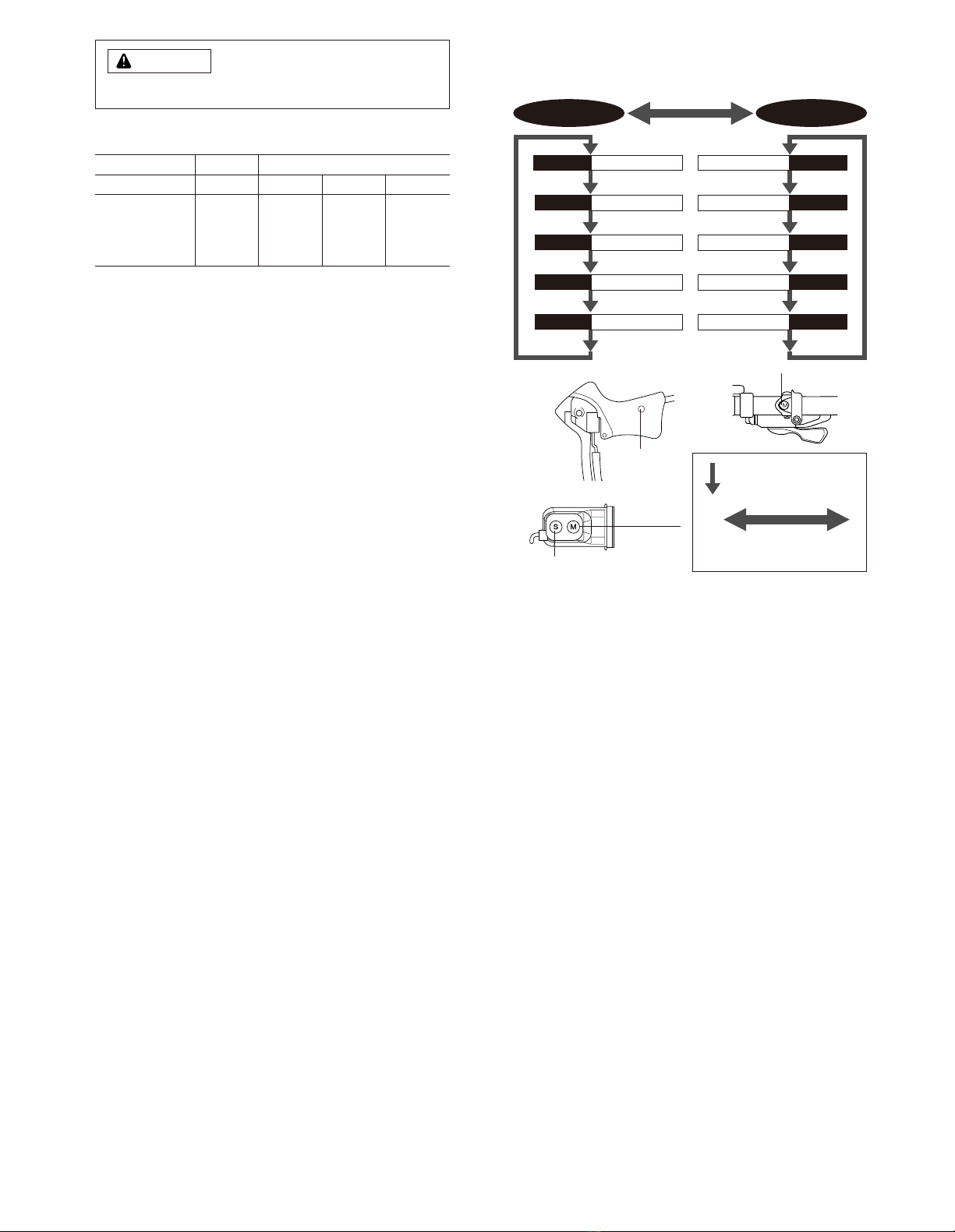
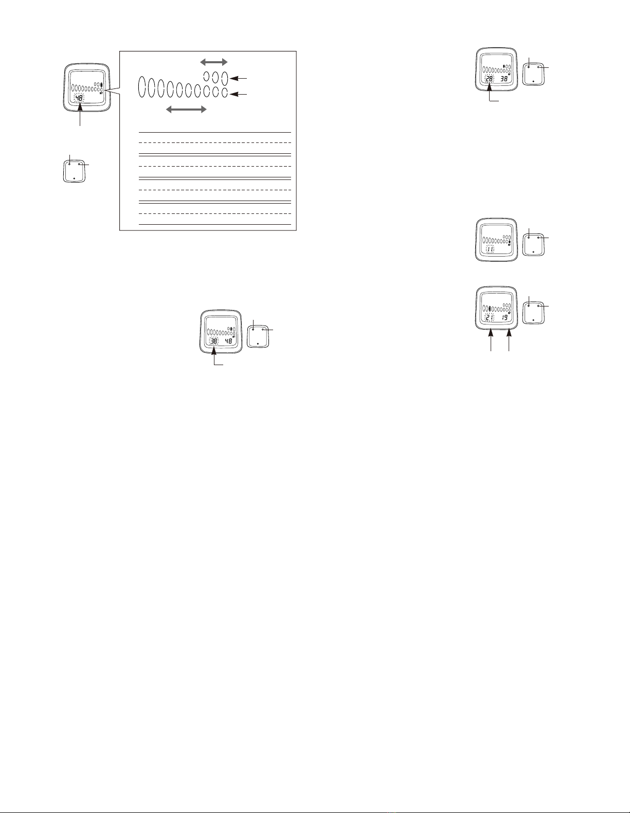
Entering the number of chainring and sprocket teeth
The display will then change to that shown in fig10.
Enter the values staring from the outer chainring. “48”(or “42”if no. 3 or 4
has been selected) will flash on the display. Press switch “A”until the
desired setting is displayed, and then press switch “B”to accept the new
setting. (Setting range: 60- 40)
The “--”is displayed once for every five times the value is changed.
If this value is set for the outer chainring by switch “B”, all gear indicator
related screen display will be eliminated.
Fig.10
No. of teeth for
largest chainring
When switch “A”is pressed for 2
seconds or more, the value will
change rapidly.
After the value for the largest
chainring has been set, the display
will change to that shown in Fig.
1. For single chainwheel, press
switch “A”until “--”is displayed
and then press switch “B”.
Fig.11
Enter the number of teeth for the
inner chainring (for double front
chainwheel) or the middle
chainring (for triple front
chainwheel).
“38”(or “32”if no. 3 or 4 has been
selected) will flash on the display.
This position can be set from 20 -
50 by the same procedure of
setting outer chainring. After
setting the inner chainring or the
middle chainring, the display will
change to that shown in fig12.
Enter the number of sprocket
teeth.
The display will then change to
that shown in fig13.
When using a double front chainwheel, press switch “A”once so that “--”
is displayed, and then press switch “B”once to set, the front chainwheel
will then be registered as a double front chainwheel and the display will
change to show the rear sprocket settings.
(Note: Switch “B” should be
pressed and released immediately. If you press it for more than 2
seconds, the next rear derailleur type will be displayed for data entry.)
When using a triple front chainwheel, the value can be set from 15 to 34
by the same procedure of setting middle chainring.
Enter the number of teeth for each
sprocket by the same procedure as
that used for the chainrings.
Press switch “A”to set the desired
number of teeth, and then press
switch “B”to accept the setting.
The value can be set from 11 to
42. Once the setting for smallest
sprocket through to the 7th
sprocket have been made, the
display will change to that shown
in fig14.
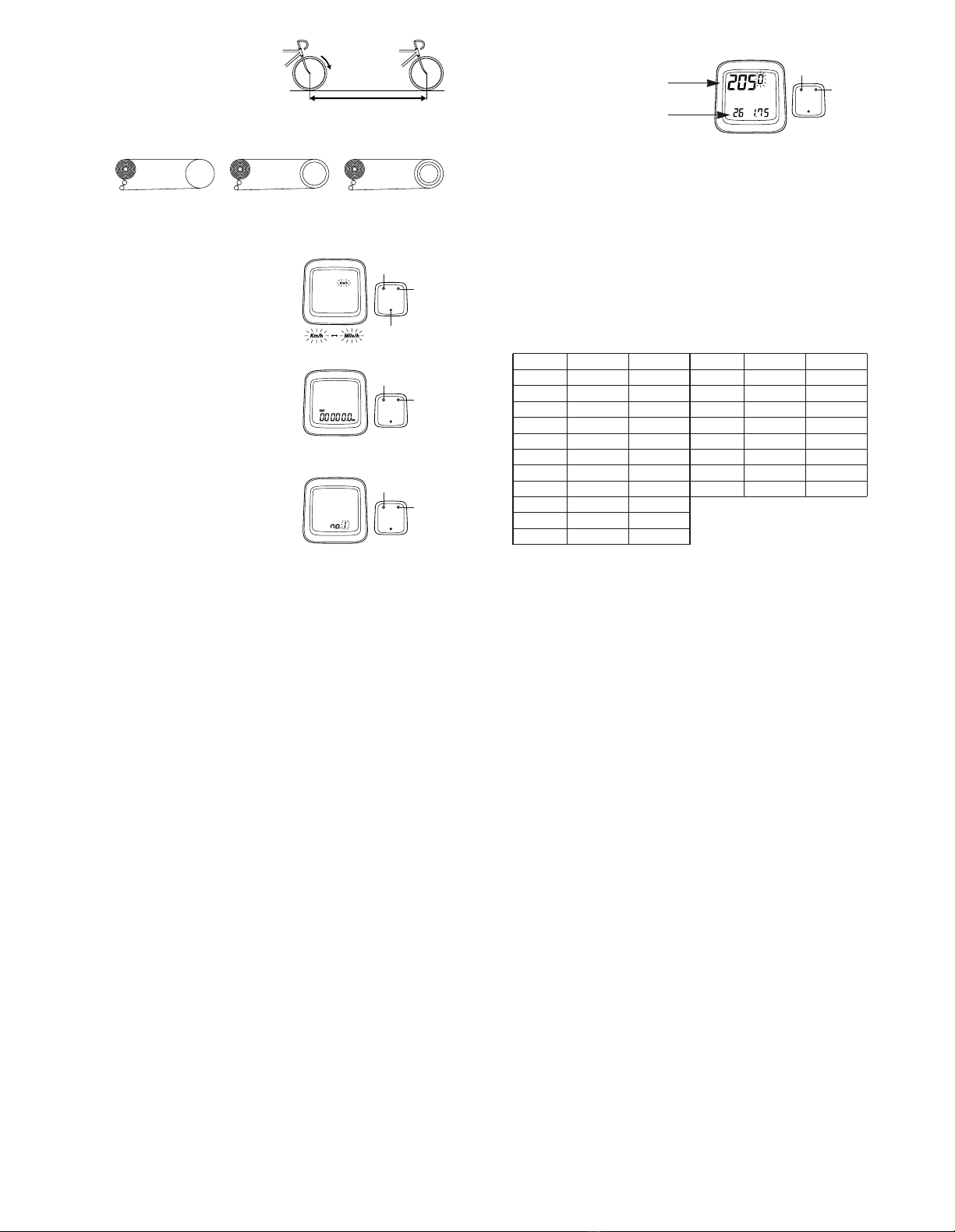
The following tooth numbers are pre - set into the computer
Front chainrings 48 x 38 x 28 (3 chainrings)
Cassette 11,12,13,14,15,16,17,18,19, 21 (10 sprockets)
No.1
No.2
Front chainrings 48 x 38 x 28 (3 chainrings)
Cassette 11,12,13,14,15,16,17,18,19, 21 (10 sprockets)
Front chainrings 42 x 32 x 22 (3 chainrings)
Cassette 11,12,13,16,18, 21, 24,28,32 (9 sprockets)
No.3
Front chainrings 42 x 32 x 22 (3 chainrings)
Cassette 11,12,13,16,18, 21, 24,28,32 (9 sprockets)
No.4
Inner
chainring
Outer
chainring
Front chainring
Rear sprocket
Low gear Top gear
No. of middle
chainring teeth
Fig.12
Fig.13
Fig.14
No. of 7th sprocket
plus one teeth
No. of 7th sprocket
No. of inner chainring teeth
“28”(or “22”if no. 3 or 4
has been selected)
Switch “A”:
Change
value
Switch “B”:
Accept
Switch “A”:
Change
value
Switch “B”:
Accept
Switch “A”:
Change
value
Switch “B”:
Accept
Switch “A”:
Change
value
Switch “B”:
Accept
Switch “A”:
Change
value
Switch “B”:
Accept

If the cassette has seven sprockets, press switch “A”once to change the
flashing “21”to “--”, and then press switch B once. This will indicate that
there is no 8th sprocket, and the operation for entering the number of
sprocket teeth will be complete.
If the cassette has 8 sprockets, enter the number of teeth for this position
and follow the same procedure as above to enter “--”in the 9th position
otherwise enter the number of teeth for the 9th sprocket. If the cassette
has 10 sprockets, enter the number of teeth for the 10th sprocket.
Checking the number of teeth entered
Once the setting of number of sprocket teeth is completed, the display will
return to the initial input display. Re check all values by repeatedly
pressing switch “B”to confirm each number of teeth. Press switch “B”once
each time and check whether the entered number of teeth are matching
with the sprocket position on
the display.
If all values entered are correct,
press switch “B”for 2 seconds
or more to continue the next
entry procedure.
Press switch “B”for 2 seconds or more
to continue the next entry procedure.
111 •••••• for Traditional rear
derailleur
222 •••••• for Rapid Rise Rear
derailleur (reverse
spring type)
(5)Entering the type of rear derailleur
The display will change to that shown in fig 15. The display will change
from “111”to “222”each time switch “A”is pressed.
This Value
Indicated
Section
The hours will advance when switch “A”is
pressed. If switch “A”is pressed continuously,
the hours will advance rapidly. Press switch “B”
once to set the hour.
The minutes section will then start flashing as
shown in Fig 17.
Set the minutes in the same procedure as for
setting the hours. The clock will then start.
Note; To reset clock
[]
Example
If the time is 10:46:23 ••••• 10:47: - -
If the time is 13:59:16 ••••• 14:00: - -
Get a display where CLK appears on the sub - display. Press switch
“B”for 5 seconds or more to change the time setting.
(6)Setting the time
(24 hour format)
The display will change to that
shown in fig 16.
Set the time to one minute later than
the current time.
To continue entering data for a different bicycle number, change the sub-
display to a display other than the CLK display, and then press switch “B”
for 5 seconds or more. The press switch “A”until the bicycle number to be
entered is displayed and then press switch “B”again. Refer to “4. Changing
the setting data”for details on entering new data.
•Meter (CR-2032 battery)
Insert the battery so that the (+) side
is visible as shown in Fig. 18, and
then tighten the battery cap.
The battery which is installed at the
time of purchase is for monitoring
purposes. If the low battery
indicator appears, replace the battery
as soon as possible.
•Sensor (LR44 battery)
Insert the battery so that the (+) side
is visible as shown in Fig. 19, and
then tighten the battery cap.
Note;
If the speed does not display
correctly even though the LO BAT
low battery indicator does not
appear, replace the sensor battery.
Replacing the battery
Fig.18
Fig.19
Close
Close
Open
Open
CR-2032
LR44
Fig.15
Fig.16
Fig.17
Switch “A”:
Select
Switch “B”:
Accept

@@@@@@@@e?
@@@@@@@@e?
@@h?
@@h?
@@h?
@@h?
@@h?
@@h?
@@@@@@@@e?@@@@@@@@?e@@@@@@@@e?@@@@@@@@?e@@@@@@@@e?@@@@@@@@?e@@@@@@@@e?@@@@@@@@?e@@@@@@@@e?@@@@@@@@?e@@@@@@@@e?@@@@@@@@?e@@@@@@@@e?@@@@@@@@?e
@@@@@@@@
@@@@@@@@
@@
@@
@@
@@
@@
@@
@@
@@
@@
@@
@@
@@
@@
@@
@@
@@
@@
@@
@@
@@
@@
@@
@@
@@
@@
@@
@@
@@
@@
@@
@@
@@
@@
@@
@@
@@
@@
@@
@@
@@
@@
@@
@@
@@
@@
@@
@@
@@
@@
@@
@@
@@
@@
@@
@@
@@
@@
@@
@@
@@
@@
@@
@@
@@
@@
@@
@@
@@
@@
@@
@@
@@
@@
@@
@@
@@
@@
@@
@@
@@
@@
@@
@@
@@
@@
@@
@@
@@
@@
@@
@@
@@
@@
@@
@@
@@
@@
@@
@@
@@
@@
@@
@@
@@
@@
@@
@@
@@
@@
@@
@@
@@
@@
@@
@@
@@
@@
@@
@@
@@
@@
@@
@@
@@
@@
@@
@@
@@
@@
@@
@@
@@
@@
@@
@@
@@
@@
@@
@@
@@
@@
@@
@@
@@
@@
@@
@@
@@
@@
@@
@@
@@
@@
@@
@@
@@
@@
@@
@@
@@
@@
@@
@@
@@
@@
@@
@@
@@
@@
@@
@@
@@
@@
@@
?@@
?@@
?@@
?@@
?@@
?@@
?@@@@@@@@
?@@@@@@@@
?@@@@@@@@?e@@@@@@@@e?@@@@@@@@?e@@@@@@@@e?@@@@@@@@?e@@@@@@@@e?@@@@@@@@?e@@@@@@@@e?@@@@@@@@?e@@@@@@@@e?@@@@@@@@?e@@@@@@@@e?@@@@@@@@?e@@@@@@@@
@@g
@@g
@@g
@@g
@@g
@@g
@@@@@@@@
@@@@@@@@
@@
@@
@@
@@
@@
@@
@@
@@
@@
@@
@@
@@
@@
@@
@@
@@
@@
@@
@@
@@
@@
@@
@@
@@
@@
@@
@@
@@
@@
@@
@@
@@
@@
@@
@@
@@
@@
@@
@@
@@
@@
@@
@@
@@
@@
@@
@@
@@
@@
@@
@@
@@
@@
@@
@@
@@
@@
@@
@@
@@
@@
@@
@@
@@
@@
@@
@@
@@
@@
@@
@@
@@
@@
@@
@@
@@
@@
@@
@@
@@
@@
@@
@@
@@
@@
@@
@@
@@
@@
@@
@@
@@
@@
@@
@@
@@
@@
@@
@@
@@
@@
@@
@@
@@
@@
@@
@@
@@
@@
@@
@@
@@
@@
@@
@@
@@
@@
@@
@@
@@
@@
@@
@@
@@
@@
@@
@@
@@
@@
@@
@@
@@
@@
@@
@@
@@
@@
@@
@@
@@
@@
@@
@@
@@
@@
@@
@@
@@
@@
@@
@@
@@
@@
@@
@@
@@
@@
@@
@@
@@
@@
@@
@@
@@
@@
@@
@@
@@
Trouble Shooting
* Speed is not displayed.
•Check that the speed sensor and the main unit are
positioned correctly (distance and facing direction).
•Check that the positions of the speed sensor and
magnet are correct.
•Check that the main unit is fixed correctly to the
bracket.
* Display does not appear or is faint.
•Poor main unit contact, or battery is depleted. Replace
the main unit battery with a new one.
* Incorrect data is displayed.
•Press the A/C button to re -enter the data.
* Display is dark.
•This is because the main unit has become hot and has
been affected by long-term exposure to direct sunlight,
such as can occur during hot weather.
Store the main unit in a cool, shady place so that it can
cool down and return to normal.
* Data display movement is slow.
•The computer operating temperature range is –10°C to
50°C. Check that the temperature is not lower than
–10°C.
* Gear indicator (bar) does not display correctly.
•Lift up the plate spring that the sensor
is mounted on as shown
in the illustration.
Rubber sensor pad
Plate spring
t
This manual suits for next models
5
Table of contents