Flight Display Systems FDPWRU28-2 User manual

Rev:
B
Revision Date:
02/17/2014
Page 1 of 9
MAN –FDPWRU28-2
*Manufactured by MILIC, LLC with marketing support from Flight Display
Systems. This product does not have FAA PMA approval.
FDPWRU28-2
Installation and Operation Manual
Dual USB Charger
TECHNICAL SUPPORT
470-239-7421, or
www.FlightDisplay.com

Rev:
B
Revision Date:
02/17/2014
Page 2 of 9
MAN –FDPWRU28-2
FDPWRU28-2
Dual USB Charger
© 2014 Flight Display Systems. All Rights Reserved.
Flight Display Systems
6435 Shiloh Road, Suite D
Alpharetta, GA 30005
678-867-6717 Phone
678-867-6742 Fax
www.FlightDisplay.com
For the most current copy of all product manuals, please visit our website at
www.FlightDisplay.com

Rev:
B
Revision Date:
02/17/2014
Page 3 of 9
MAN –FDPWRU28-2
Table of Contents
General Information ...............................................................................................................4
1. Front View..........................................................................................................................4
2. Specifications .....................................................................................................................5
Mechanical Installation............................................................................................................6
Technical Drawing ..................................................................................................................7
Technical Support ...................................................................................................................8
Instructions for Continued Airworthiness.........................................................................8
Warranty Information.............................................................................................................9
Log of Revisions ......................................................................................................................9

Rev:
B
Revision Date:
02/17/2014
Page 4 of 9
MAN –FDPWRU28-2
General Information
The FDPWRU28-2 is used to convert 28V power from the aircraft to 5.2V power which can be
used to power and/or charge small auxiliary items. Each unit has 4 Amps of total charging
capacity. There are two output connectors rated 5.2V @ 2 Amps continuous each. Two
devices may be charged with full 2 Amps of charging current at the same time or one device
may be charged with up to 4 Amps continuous current. The charger provides 5.2V DC for full
charging capability to carry on devices such as media players, smart phones, tablets, as well
as, other personal electronics carried onto the aircraft. The dual USB charger is compatible
with the latest Apple® media products and similar devices.
The dual ports may be used to charge many other devices that have USB style charging
connectors, but not all devices have been tested for compatibility and operation cannot be
guaranteed. The FDPWRU28-2 must be connected to a source of 28 V DC power. The
FDPWRU28-2 does not provide communication to any device; its sole purpose is to charge a
device through a USB interface cable.
Front View

Rev:
B
Revision Date:
02/17/2014
Page 5 of 9
MAN –FDPWRU28-2
Specifications
Weight
3.4 oz.
Power Input
28V DC @ 1A
Power Output
5.2V DC @4A
Operating Temperature
-50°C –120°C
Compatibility
Latest apple media products/small
devices
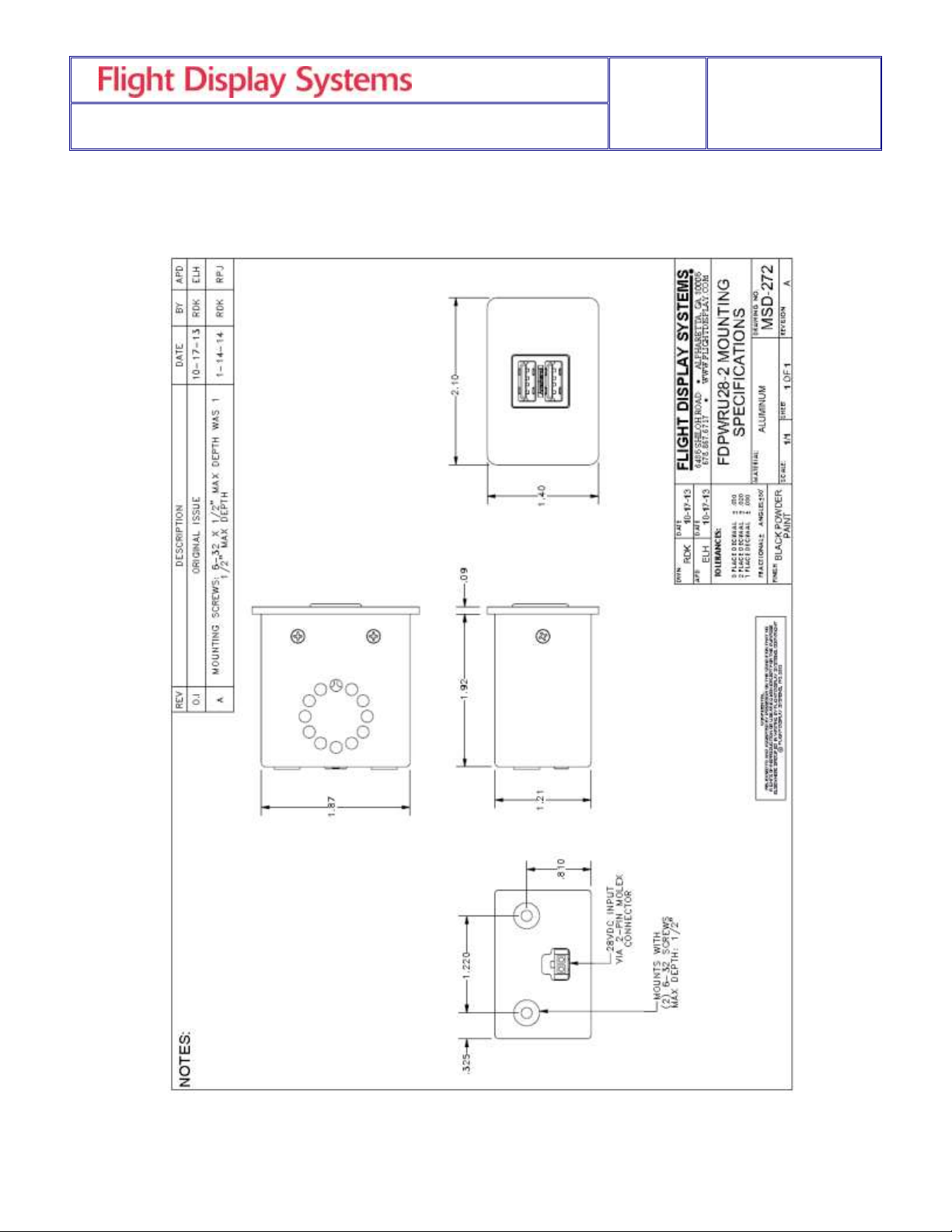
Dimensions
2.10” (W) x 1.40” (H) x 1.92” (D)
Connector
2-Pin Molex Connector
Materials
Aluminum
Testing
DO160 Section 21 Category M
PINOUT FOR FDPWRU28-2
- Connector: Molex P/N 43645-0200
+ Crimp Contacts: Molex P/N 43030-0007
PIN NUMBER
DESCRIPTION
1
28VDC INPUT
2
28VDC GROUND

Rev:
B
Revision Date:
02/17/2014
Page 6 of 9
MAN –FDPWRU28-2
Mechanical Installation
The unit may be mounted horizontally or vertically.
The installation process for the FDPWRU28-2 is accomplished with minimal hardware,
including these installation steps:
1. Cut a mounting hole the appropriate size for the unit in the mounting surface.
See “ FDPWRU28-2 Drawing”
* FDS highly recommends receiving the product first to ensure the best
possible fit during installation.
2. Attach the Molex 2-pin female connection and place the FDPWRU28-2 into
the mounting hole.
3. Secure the unit with 6-32 machine screws. Maximum screw protrusion into
the unit is .50 inch.
Rev:
B
Revision Date:
02/17/2014
Page 7 of 9
MAN –FDPWRU28-2
Technical Drawings

Rev:
B
Revision Date:
02/17/2014
Page 8 of 9
MAN –FDPWRU28-2
Technical Support
Should you have any questions concerning this product or other Flight Display Systems
products, please contact our Product Support representatives at (678) 867-6717.
Flight Display Systems
6435 Shiloh Road, Suite D
Alpharetta, GA 30005
Phone: +1 (678) 867-6717
Fax: +1 (678) 867-6742
Email: [email protected]
For further product information, technical data and sample wiring diagrams, please click on
the Dealers section of our web site at www.FlightDisplay.com
Instructions for Continued Airworthiness
The FDPWRU28-2 is designed not to require regular general maintenance.
Rev:
B
Revision Date:
02/17/2014
Page 9 of 9
MAN –FDPWRU28-2
Warranty Information
Flight Display Systems warrants all our products against material or manufacturing defects.
We provide a two-year warranty to all Corporate Aviation Customers, a one-year warranty to
Government/Special Missions and a one-year warranty on all headset equipment. Our
warranty begins on the date of installation. *The warranty registration card must be returned
upon installation in order to validate the warranty. Any warranty registration not returned during
this time period will default to the date of purchase as the warranty start date.
If product support is required, please call our Technical Support team at 470-239-7421 to
obtain assistance. If the return of the unit to the factory is required, an RMA number will be
issued at that time. Flight Display Systems will, upon receipt of the failed hardware,
remanufacture or replace the unit at our discretion.
Flight Display Systems will pay Ground Return Shipping charges for warranted items returned
to the customer.Charges for express shipment will be the responsibility of the sender.
This warranty is not transferable. Any implied warranties expire at the expiration date of this
warranty. We shall not be liable for incidental or consequential damages.
This warranty does not cover a defect or failure that has resulted from improper or
unreasonable installation, use or maintenance, as determined by Flight Display Systems. This
warranty is void if there is any attempt to disassemble or open this product without factory
authorization.
Any labor charges associated with the removal of product or related troubleshooting by a firm
other than Flight Display Systems will not be covered.
Revisions Log
Rev
Date
Page
Description
A
01/10/2014
Original Issue
B
02/17/2014
5
Additional Drawing to include the identification of Pin 1 of the
Molex connector
Table of contents
Popular Batteries Charger manuals by other brands


Sterling Power
Sterling Power Pro Batt Ultra user manual

Stuart Turner
Stuart Turner Mainsboost Charger MBC 12 Installation, operation & maintenance instructions

ZOLL
ZOLL SMART Operator's guide

Inter-m
Inter-m PB-6207B Operation manual

Waeco
Waeco PerfectCharge MCA1215 Installation and operating manual

IBM
IBM ThinkPad Battery Charger II user guide


