Flight Light L810LED Manual


MWI-05-001 – Rev. B

MWI-05-001 – Rev. B
Table of Contents
1. Introduction .......................................................................................................................................... 1
1.1 About the manual................................................................................................................................ 1
2. Safety Measures.................................................................................................................................... 2
3. Installation ............................................................................................................................................ 3
3.1Wiring Diagram .................................................................................................................................... 3
3.2 Single Head Obstruction Lights ........................................................................................................... 4
3.2.1 Single Head Obstruction Light with Photocell ............................................................................. 4
3.2.2 Mounting Options:....................................................................................................................... 5
3.3 Dual Head Obstruction Light............................................................................................................... 6
3.3.1 Dual Head Obstruction Light with Photocell................................................................................ 6
3.3.2 Dual Head Obstruction Light with Flasher and Photocell ............................................................ 6
3.3.3 Dual Head Obstruction Light with Transfer Relay........................................................................ 7
3.3.4 Dual Head Obstruction Light with Transfer Relay and Photocell................................................. 7
3.3.2 Mounting Options:....................................................................................................................... 8
4. Replacement Parts .................................................................................................................................... 9
5. Maintenance and Repair..................................................................................................................... 11
6. Limited Warranty ................................................................................................................................ 12

MWI-05-001 – Rev. B
1
1. Introduction
The Flight Light model L810 obstruction light provides an LED-based solution to the FAA style
of steady burning red obstruction light. The product complies completely with FAA Advisory
Circular AC 150/5345-43H and FAA EB-67D and is certified to these latest standards.
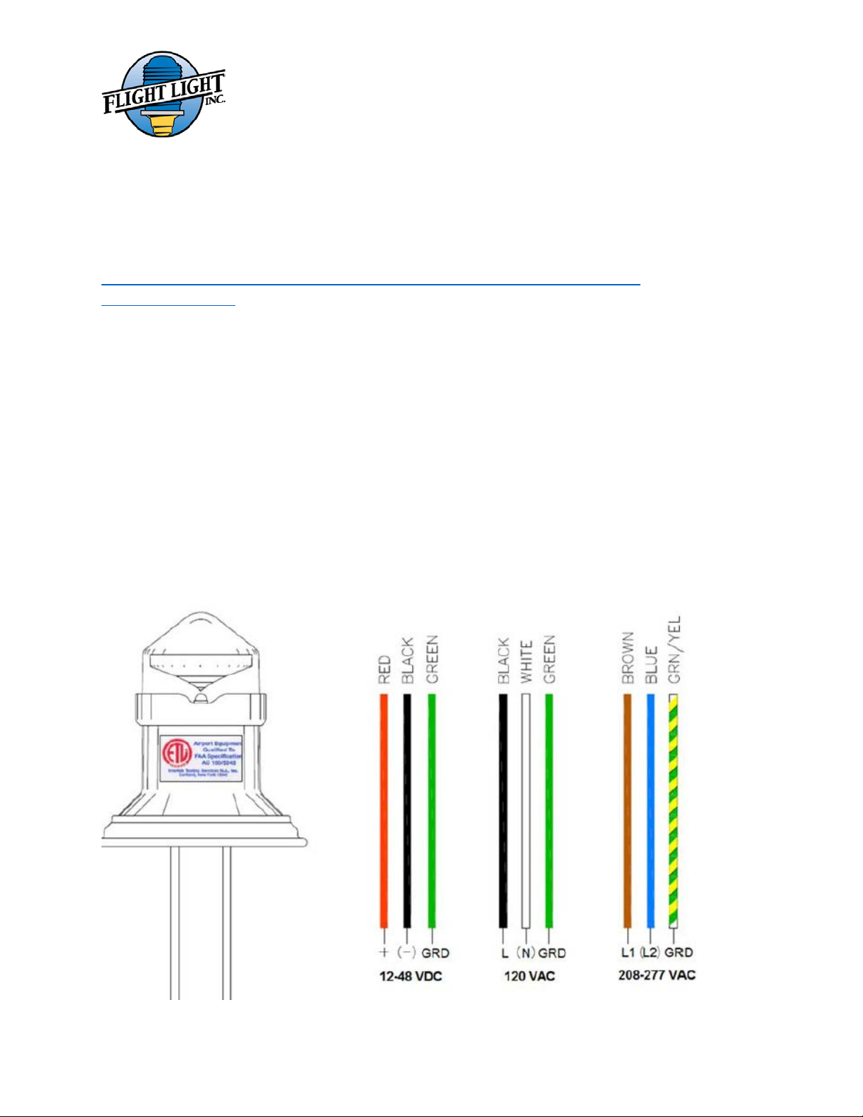
Input Voltage: 120VAC, 208-277VAC, 12-48VDC
Power Consumption: 1.8W for DC and 3.3W for AC
Applicable Specifications: FAA AC 150/5345-43G plus FAA supplemental requirements for
LED light source EB-67
Operating Temperature Range: -55 to +55 degrees Celsius
Humidity: to 95% relative humidity
Wind: Wind speeds up 150 mph
Wind Blown Rain: Exposure to wind-blown rain from any direction
Salt Fog: Exposure to salt-laden atmosphere
The installation and maintenance should be done by authorized personnel only.
For questions or guidance during the installation process, please contact our office. Our
engineers and technician are always available to help you.
Phone number: 1-800-806-3548
1-916-394-2800
1.1 About the manual
This manual contains important information regarding the safety, operation, and maintenance of
this product. Before using the product, read and understand all cautions warning, instructions, and
product labels. Failure to do so could result in injury and/or void the warranty.

MWI-05-001 – Rev. B
2
2. Safety Measures
You must know whether your lighting system is powered by AC or DC before installing the
fixture. AC models work on a range of 100 to 277VAC and DC models operate from 12 to
48VDC. The lights are designed to be installed in a parallel circuit, which maintains a constant
voltage and brightness for all lights.
Ensure power is off before installing or servicing lighting fixtures!
Follow the local electrical code!
Make sure the equipment is rated and approved for the environment in which you are intending
to use it. Do not operate this equipment in humid, flammable, or explosive environments unless
it has been rated for safe operation in these environments.
Use only electrical wire of sufficient gauge and insulation to handle the rated current and voltage
demand.
Route electrical wiring along a protected path. Make sure they will not be damaged by moving
equipment.
Protect components from harsh environment conditions.
Protect equipment with safety devices as specified by applicable safety regulations.
Before starting this equipment, check all safety interlocks, fire –detection systems, and protective
devices such as panels and covers. Make sure all devices are fully functional. Do not operate the
system if these devices are not working properly.
Never operate equipment with a known malfunction.
Do not attempt to operate or service electrical equipment if standing water is present.
Do not touch exposed electrical connections on equipment while the power is ON!
Wiring and electrical design should be authorized by an electrical contractor.
To provide maximum protection from surges, ensure that the system ground is tested and
provides less than 25 ohms to ground resistance.
MWI-05-001 – Rev. B
3
3. Installation
The FAA has published guide specifications for the installation and maintenance of obstruction
lighting products. FAA advisory circulars may be obtained by direct internet access or by
contacting FAA.
Direct Internet Access:
https://www.faa.gov/documentLibrary/media/Advisory_Circular/AC_70_7460-
1L_with_chg_1.pdf
FAA AC 70/7460-1L
The installation of a new complete L810 LED light is similar to that of an incandescent light
source assembly.
1. Verify that all supply power is off
2. Use the below wiring diagram and ensure your incoming power is matching the voltage
the light was built for.
3. Connect the wires from the fixture to the wires from the power source
4. Make sure the connection is done in a protected, waterproof enclosure.
3.1 Wiring Diagram

MWI-05-001 – Rev. B
4
3.2 Single Head Obstruction Lights
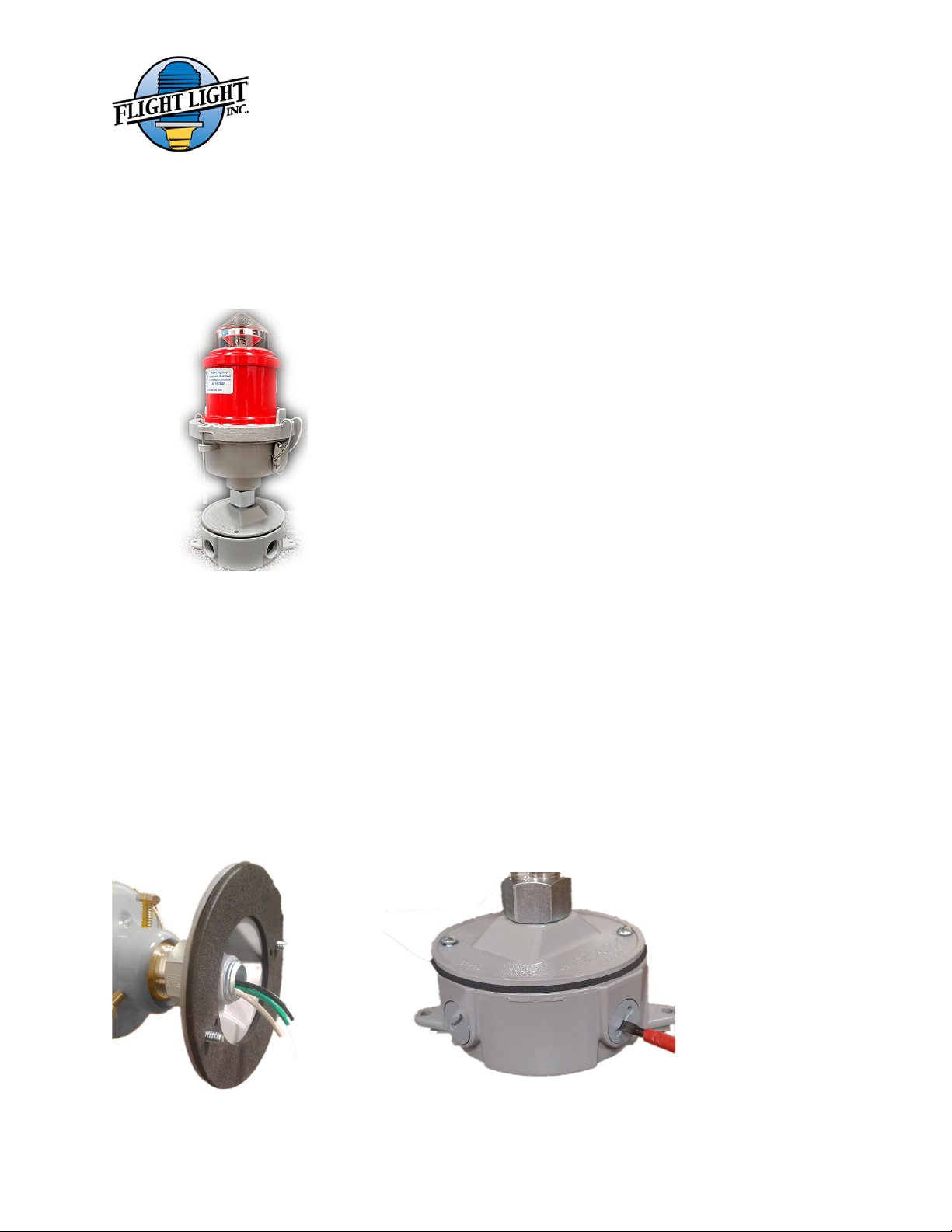
3.2.1 Single Head Obstruction Light with Photocell
Height: 9”
Width: 5.75”
Weight: 3.30 Lbs
Height: 9”
Width: 10.5”
Weight: 4.10 Lbs
MWI-05-001 – Rev. B
5
3.2.2 Mounting Options:
A. Low Surface Mount
1. Mount box to surface
2. Install fittings or conduit using sealing compound on threads.
3. Pull supply wires into box.
4. Thread the light into the cover and run the wires through the top hole and through the gasket.
See picture below. Connect/Splice them to the incoming power cables.
5. Attach system ground wire under head of green screw in box.
6. Center cover gasket evenly. Locate pre-perforated holes in the gasket and install the gasket
so they align with the mounting holes in the box. Install cover with the two screws provided.
7. Use caulking around cover.
8. Cover the conduits that are not used with the plugs provided.

MWI-05-001 – Rev. B
6
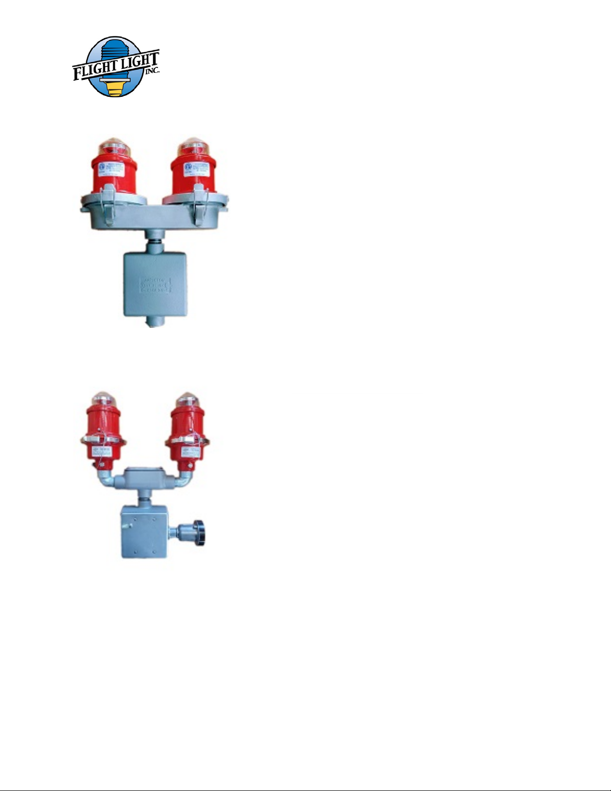
3.3 Dual Head Obstruction Light
3.3.1 Dual Head Obstruction Light with Photocell
3.3.2 Dual Head Obstruction Light with Flasher and Photocell
Height: 9”
Width: 11”
Weight: 6.55 Lbs
Height: 15 ½”
Width: 11”
Weight: 10.20 Lbs
MWI-05-001 – Rev. B
7
3.3.3 Dual Head Obstruction Light with Transfer Relay
3.3.4 Dual Head Obstruction Light with Transfer Relay and Photocell
Height: 14”
Width: 11”
Weight: 10.50 Lbs
Height: 14”
Width: 11”
Weight: 11.25 Lbs
MWI-05-001 – Rev. B
8
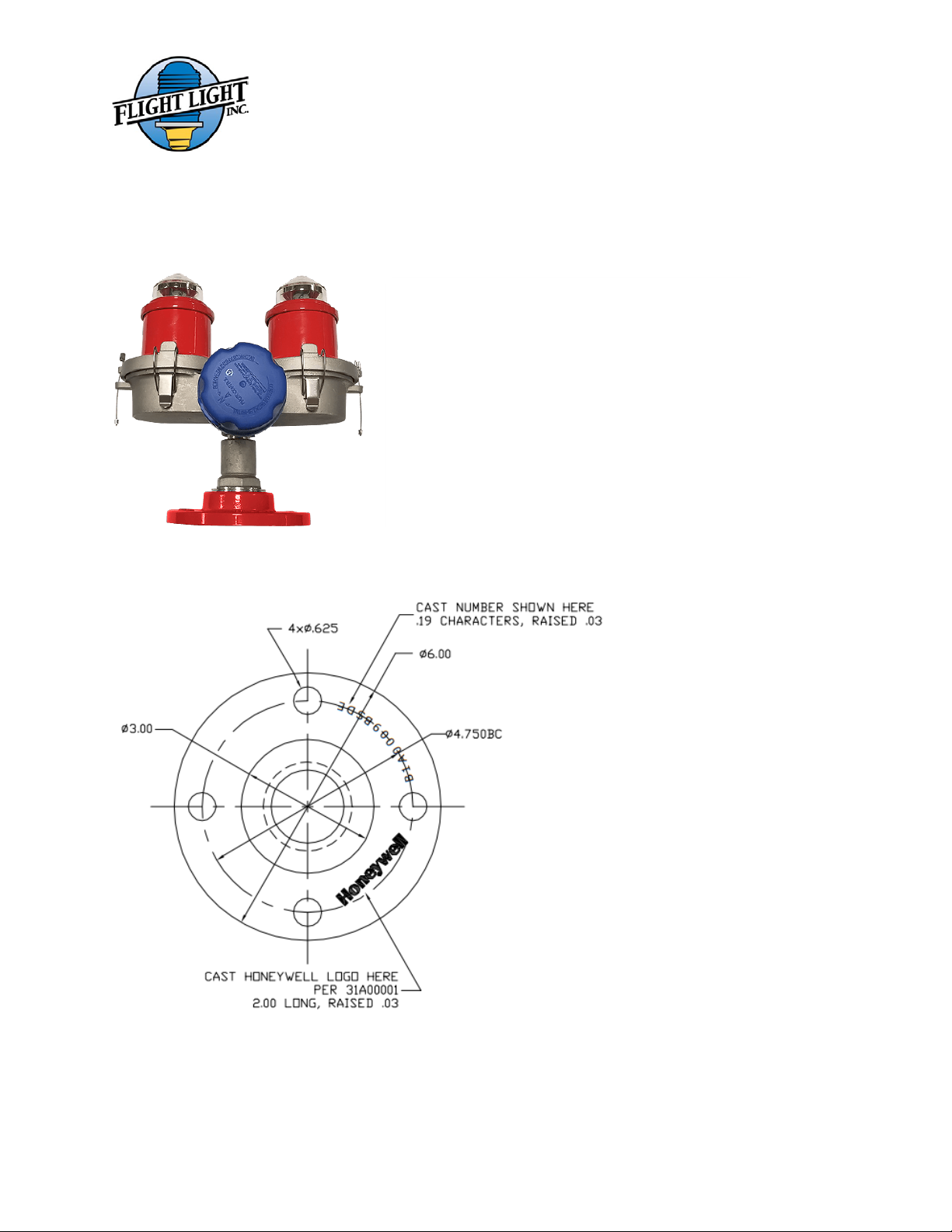
3.3.2 Mounting Options:
A. Floor Flange
For a quick installation on top of a flat
surface, we offer the 6” Diameter Floor
Flange with 2” thread.
The connection to the floor flange is done
through our FAA 2” Frangible Floor flange.
The bolts for the floor flange are not provided
by Flight Light.

MWI-05-001 – Rev. B
9
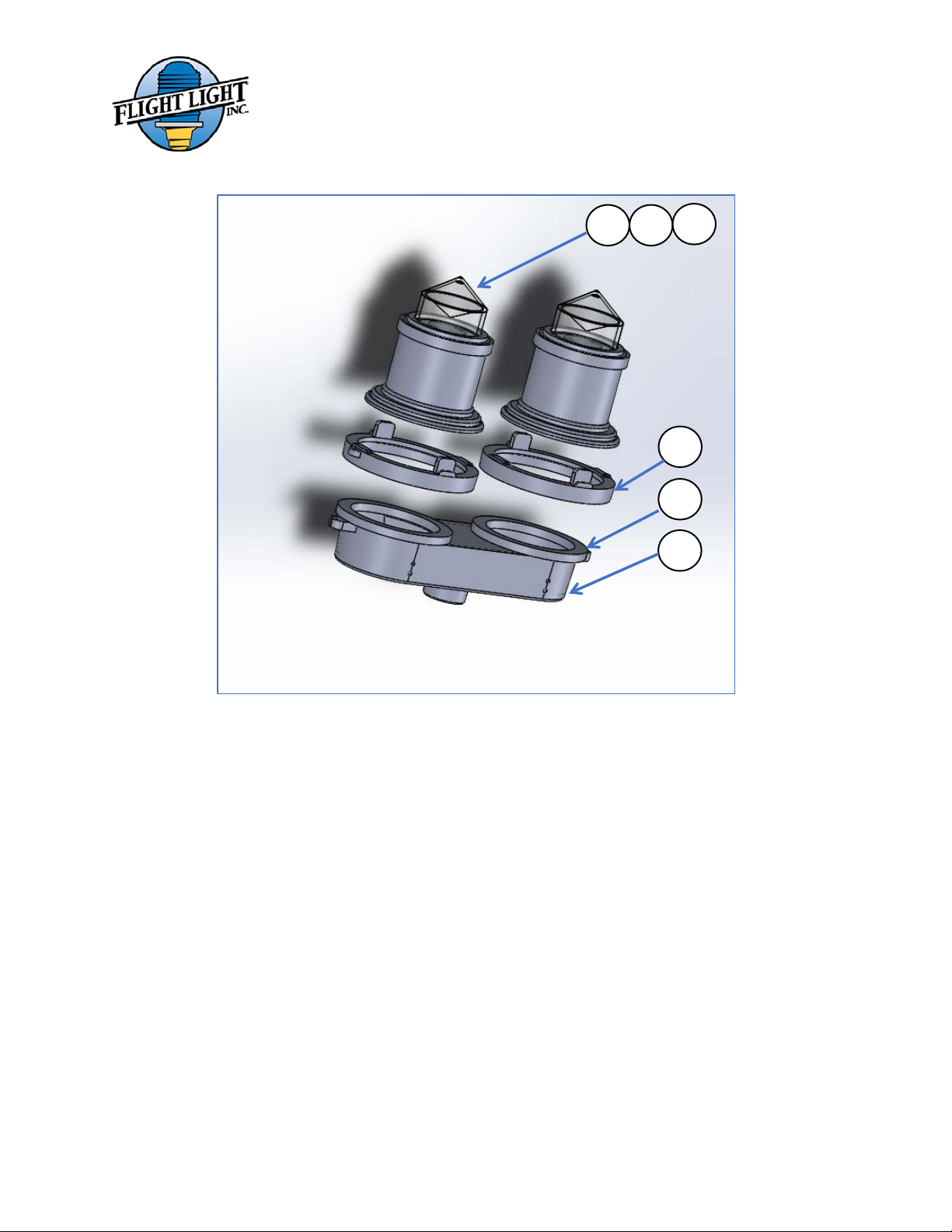
4. Replacement Parts
No.
Part Number
Part Description
1.
FL-810LED120VAC
120VAC L810LED V1 Assembly (engine)
2.
FL-810LED208-277VAC
220-277VAC L810LED V1 Assembly (engine)
3.
FL-810LED12-48VDC
12-48VDC L810LED V1 Assembly (engine)
4.
22-SK4545
Clamp Ring
5.
22-SK4454
Neoprene Gasket
6.
22-SK4546
Single Casting L-810
7.
22-SK4547
Double Casting L-810
1
6
4
5
2
3
MWI-05-001 – Rev. B
10
1
2
3
4
5
7

MWI-05-001 – Rev. B
11
5. Maintenance and Repair
No regularly scheduled maintenance is required for the unit.
Flight Light warranties the light output of the L810LED to meet and exceed FAA requirements
for a five-year period.
Life time expectancy is 70,000+ hours.
The LED board is sealed inside the top head assembly. In case of failure the entire engine must
be replaced.
1. Ensure power is off before servicing the lighting fixture
2. Open the Clamp Ring that is holding the top assembly and the bottom casting together
3. Remove the existing engine
4. Run the wires from the new engine through the bottom casting and position the unit over
the gasket located in the bottom casting
5. Secure the unit by closing the clamp ring
The functionality of the Flight Light L810LED Obstruction lights is not affected by their use in
conjunction with another LED lights or another manufacture’s LED obstruction lights.
The performance and life time expectancy of the Flight Light L810LED obstruction light(s) may
be affected if controlled by another manufacture’s controller. In consequence, if the lights are
used with another’s manufacture controller, the warranty will be voided. We don’t recommend
using our L810LED obstruction lights with another controller, but our NV1200 Series.

MWI-05-001 – Rev. B
12
6. Limited Warranty
Duration of the Warranty: Flight Light Inc. warrants all of the goods which it has manufactured to be
free of material defects for the following durations.
Lamps: For a period of 90 days from the date of shipment to Buyer. Product liability is limited to lamp
replacement and does not include incidental labor.
FAA products: For a period of one year from the date of installation or two years from the date of
shipment to Buyer.
LED Light Fixtures: For a period of 2 years from the date of shipment to Buyer. Complete Systems:
Systems including at least one Flight Light Inc. Controller and one Flight Light Inc. LED Light Fixture, for a
period of 5 years from the date of shipment to Buyer.
Buyer’s Remedies: If any such goods are found to be materially defective within the warranty period,
Flight Light Inc. agrees to attempt to repair, and if unable to repair, to replace the defective goods
without charge to Buyer.
Buyer’s remedy with respect to such goods is limited to repair or replacement. For goods not
manufactured by FLI, Buyer agrees to accept as its sole remedy the warranty, if any, offered by the
manufacturer or manufacturers of such goods. FLI makes no warranties, express or implied, other than
those stated in this paragraph.
Warranty Exclusions: Flight Light Inc. shall not be liable under this warranty if any of the following
conditions apply:
1) Unauthorized personnel attempt any repairs to Flight Light Inc. products without Flight Light
Inc. consent.
2) Products are damaged by natural phenomenon, misuse, abuse, accident, alteration, or
incorrect electrical current or voltage.
3) Products are improperly installed, or damaged in shipping.
Warranty Limitations
FLI makes no warranties, express or implied, other than those stated herein. FLI does not warranty the
workmanship of the installer, damage caused by acts of nature, vandalism, improper installation, or
damage caused by improper maintenance. The warranty period of LED fixtures covered under the 5-year
system warranty is reduced to two years when fixtures are subjected to abrasive materials or chemicals.
FLI reserves the right to either repair or replace any defective component covered under the terms of any
of its warranties. FLI is not an engineering firm and makes no expressed or implied warranty as to the
applicability of its products or systems in any specific situation, application or location: such decisions are
the responsibility of the owner, design engineer and/ or others. Therefore, as to all goods sold by FLI, FLI
hereby disclaims any implied warranty of merchantability or implied warranty of fitness for a particular
purpose and Buyer agrees that FLI shall not be liable for any special, indirect, incidental, consequential or
liquidated damages of any kind, whether the Buyer’s or any other claim is based upon contract, tort or
any other legal theory.
Table of contents
Other Flight Light Lighting Equipment manuals


