flight of harmony Infernal Noise Machine User manual

Infernal Noise Machine
flight of harmony

2/9
I.N.M. Features
IMP:
Domains (frequency range groups)•
4 switch-selectedo
Frequency adjustment•
Coarse and Fineo
Fine scaling adjustment (relative to Coarse)o
5:1 to 25:1
Range adjustment (range of frequency variance within domain)•
Coarse and Fineo
Fine scaling adjustment (relative to Coarse)o
5:1 to 25:1
“Tone” control•
Variable between low-pass and all-passo
Adjustment also varies phase interaction
Control Voltage (CV) inputs•
Frequency: 0 to +5Vo
Range: 0 to +5Vo
Voltage-Controlled Oscillator (VCO):
Waveforms•
Squareo
Sawo
Rampo
Triangleo
Sineo
Variable base frequency•
~0.5Hz – ~140kHZo
Temperature compensatedo
1V/octo
CV input: ±12Vo
Frequency Modulation•
Selectable modulation sourceo
Noise Signal from Imp
External signal
Variable modulation deptho
External signal inputo
Level controlo
Dual Voltage-Controlled Bandpass Filter (VCBPF), one per channel:
Selectable Input signal•
VCO waveformso

3/9
IMP outputo
Variable Center Frequency (f• c)
CV input: ±12Vo
CV attenuatoro
Variable Gain•
Q varied with Gaino
Dual Voltage-Controlled Amplier (VCA), each channel:
Variable level•
CV input: ±12Vo
CV attenuatoro
V• outmax. = ±5V (10Vp-p)
What is it?
THIS IS NOT A MUSIC SYNTHESIZER
Get that out of your head right now.
The Infernal Noise Machine was designed towards the creation of
noise, sound effects, and for the general eld of sound design. Having said
that, the INM can create “musical” tones and sound – and quite a few of
them – but that was not the goal. It is semi-modular, which means part of the
signal path is hard-wired and cannot be changed, but it does allows some
variation and external control. It can be used completely independently,
but is intended for use with external control voltage (CV) sources to affect
or modulate various parameters, which is where the INM truly comes alive
(you will see what I mean).
So what can you do with it? Incidental sounds and ambiences, unholy
caterwauling, soundscapes from melancholy to manic, even percussion and
other traditional musical sounds. The Infernal Noise Machine is particularly
effective for making drones that evolve with time as well, with no external
sources required. The internal architecture allows for a wide range of self-
evolving, beat-frequency style tonal variations over an innite range of rates.
There is really no simple way to describe what the INM can do – you have
to nd out for yourself. This is a unique device. It requires a bit of time and
patience to get a feel for how it works, but it is worth the effort.
The INM does not operate the same way as a traditional synth.
The traditional signal path in a synthesizer can be generalized as the
following:
oscillator lter/effects/mixing output
The oscillator is the “heart”, so to speak, and everything else comes
further down the line. External modulation sources are used to vary different
aspects of the components of the chain, e.g.: oscillator frequency, lter
cutoff frequency and resonance, output level, and so on.

4/9
With the INM, the signal path is a bit different:
VCA
External
Input
ToneTone
VCO
FM
I.N.M. Imp
LPF
Noise
generator
VCF
VCF Bypass
Mod
depth
VCO
CV
VCO
Tune
level
level
VCA
VCF
VCF Bypass
Domain
Frequency
Range
Width
Infernal Noise Machine
flight of harmony
Block Diagram
11/11/2009
The voltage-controlled oscillator (VCO) is not the heart, but an
effect. The heart of the INM is the
Imp
, a voltage-controlled noise source.
The VCO is used to “color” the tone of the noise. While the actual signal
path is technically the same as traditional synths, with the Imp being used
to modulate the frequency of the VCO, the key to proper use of the INM
is that the Imp is the core, and the VCO is an effect. The control panel is
specically laid out to enforce this relationship (gure 2).
Main filter section
IMP VCO
Filter bypass VCA section
g. 2
g. 1

5/9
CONTROLS AND USAGE
Here is a brief explanation of the controls and their usage, described
in the same order as the signal path (see gure 1).
IMP
Domain, Frequency, Range and Width:
• Technically, all four
describe the same Function: what frequency the Imp puts out. The total
possible range of the Imp, however, is from subsonic to ultrasonic, and
accessed in different ways requiring multiple controls for ne-tuning.
Domain:
• The rst stage of frequency selection. Domain selects
one of four wide bands of the overall range. Four Domain is lowest, One
is highest (in frequency). Four is audio, One is nearly ultrasonic. The One
Domain is where you will nd the oddest/most ethereal Noises: static, wind,
the impression of voices. It has a lot of what seem to be dead spots, but it is
worth the time to wander the Domain and see what can be found.
When modulating the VCO, the greater effect is when the VCO
and the Noise frequencies are closer together, i.e., the effect is
minimal when the VCO is in the bass range and the Noise Domain
is in One, but extremely dominant when similar in frequency.
Frequency:
• This is the main frequency control within the selected
Domain - it sweeps over the entire Domain (depending on Range, see
following). The Fine control sweeps up to 1/5 of the size of the band that
Coarse does.
Range:
• This controls how wide of a sweep Frequency covers.
Fine control same as with Frequency.
Width:
• This one is a bit more esoteric: it controls the “width” of
the band of the current domain that the Fine controls cover, hence the “up
to 1/5”. In Domain 1, wide open is best. In Domain 1 the bands of sound
are very narrow, so it is best to set the width all the way down to nd the
hidden sweet spots.
In other words, a quarter of the possible frequency range is selected
by Domain, and the other controls select how much of that Domain the
frequency control can sweep across. The Coarse joystick is for a broad
sweep over the Domain, and the Fine joystick is for nding the perfect
“sweet spot”.
2
1 2 3 41 2 3 4
Domain
Frequency
Range/Width
g. 3

6/9
CV Level:
The CV inputs have attenuators to adjust the level of
external signals. Fully clockwise is the actual CV level, fully counter-clockwise
is full attenuation.
Tone:
The Noise generator has two output ampliers - a boost/
buffer and a low-pass lter (LPF), the Tone knob controls the mix between
these two outputs. The phase relationship between these two outputs varies
depending on the Noise frequency; sometimes in phase, sometimes 90°,
sometimes 180°, and everything in between.
VCO
CV Level:
Controls the attenuation of the external CV signal.
VCO Tune:
Tuning control to adjust the frequency of the VCO.
Mod Src:
Selects which signal is used to modulate the frequency of
the VCO.
Int
selects the Imp,
Ext
selects the
Ext In
input. The switch should
be to the
Int
position when no external source is connected.
Ext Level:
Controls the attenuation of the
Ext In
signal.
Mod Depth:
Controls how “deeply” the selected frequency
modulation (FM) source affects the VCO. Turn fully clockwise for maximum
modulation, fully counter-clockwise for zero modulation.
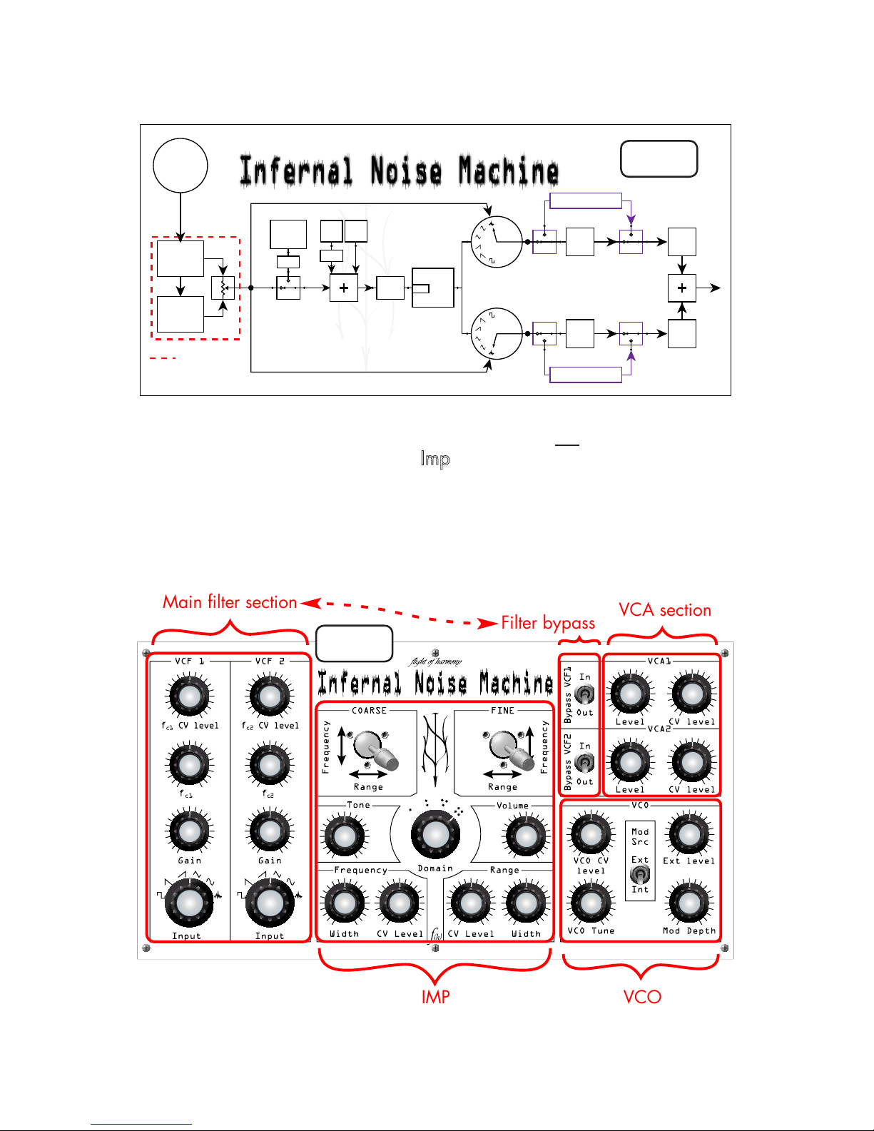
Main Filter Section:
After the VCO, the signal is routed the lter section, where it is split
into two paths to feed into the two VC bandpass lters.
Input:
These switches select one of the available waveforms to send
to the lter. The rst ve are supplied by the VCO - Square, Ramp, Saw,
Triangle, and Sine, while the sixth connects the lter input directly to the
output of the
IMP
–
think
of it as a VCO bypass.
Filter Bypass
Here we take a quick jump up by the VCA section, to the
Bypass
VCF1
and
Bypass VCF2
switches. These two switches allow you to bypass
the voltage-controlled lters (VCF) and send the selected signal (selected
with the
Input
rotary switches) directly to its voltage-controlled amplier
(VCA) with no ltering. Now back to the lters:
Gain:
Controls the gain of the lter. Fully counter-clockwise is
(almost) full attenuation, fully clockwise is maximum gain. The gain is similar
to “depth”, but also greatly varies the lter character. Actual quantitative
gain is dependent on the input frequency, so it’s all over the place.
fc1 & fc2:
These should be read as: “center frequency of lter 1 &
center frequency of lter 2”. These controls are used to change the fcof the
lter, changing what frequency band is emphasized and the overall tone
of the signal.
CV Level:
Controls the attenuation of the external CV signal. For the
VCBPF, the CV varies the center frequency.

7/9
VCA section
This is the output section. Each of the two signals is sent to a VCA,
and the outputs of the two VCA are summed together and sent to the output
jack.
Level:
The level control for the VCA. Fully clockwise is maximum
(±5V), and fully counter-clockwise is full attenuation.
CV Level:
Controls the attenuation of the external CV signal, used
here to vary the level of the output signal.
Volume control
This is the last stop for the signal on its way to the output jack,
the volume control. Turn clockwise for full volume, counter-clockwise for full
attenuation.
Rear Panel
Ext
In
Out VCO
CV
VCA1
CV
VCA2
CV
±12VAudio On
Off
Freq
CV
Range
CV
fc1
CV
fc2
CV
12VAC
±12V0-5V
IMP Filters
Here are the I/O jacks (Input/Output). Only one “O” –
Out
, the
Output, the rest are “I” – the CV inputs mentioned above with the various
CV Level attenuators,
Ext In
, the external audio input, and the power
connections.
The CV inputs have their recommended input signal voltage range
specied above the jack – please do not exceed these values. The
Range
and
Freq
are specied for 0-5VDC, but also have zener protection diodes,
just in case the wrong signal is connected.
Power
The power section, with the ubiquitous power switch and power-
on indicator. The INM requires a 12VAC 250mA source. The power jack
accepts a 2.1mm x 3.5mm cylindrical-style power plug.
A binding post is provided for connection to equipment ground if
required. The barrel of the post accepts the standard 4mm banana plug,
and can be unscrewed to attach wires or other forms of connector.
g. 4

8/9
Guarantee
All f(h) products are guaranteed against defects in manufacturing
and workmanship for the lifetime of the product. Please contact us via email
at:
support@ightofharmony.com
Stuff
There is a lot of discussion about the Infernal Noise Machine on the
Muffwiggler forums, come check it out! People have posted some excellent
demos on there. I haunt the forums as well, and new things are posted there
long before they hit the f(h) website.
http://www.muffwiggler.com/forum/index.php
A big thank you to those who have sent in suggestions and
comments, keep them coming!
Send samples to: samples@ightofharmony.com
Comments, suggestions, complaints to: ight@ightofharmony.com
Drawings and designs ©2010 ight of harmony / Red Hand Studios
http://www.ightofharmony.com
Revised: January, 2010

9/9
f(h)
Other manuals for Infernal Noise Machine
1
Table of contents
Other flight of harmony Music Equipment manuals