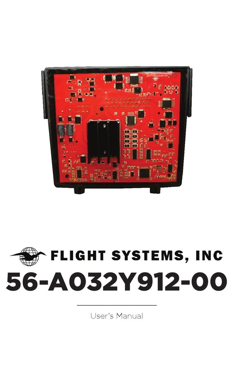
Flight Systems 56-5047-00 User manual

56-5047-00
_________________
User’s Manual


Table of Contents
2 | Overview and Features
| Unpacking and Inspection
3 | Removal and Installation
4 | Voltage Adjust
| Factory Default
5 | Troubleshooting
6 | Fault Codes
9 | Warranty Information
Back | Repair and Technical Support
1

Overview and Features
• Exact replacement for Onan© 300-5047 control modules
• Improved circuit design over OEM
• Over-sized heatsink for cooler operation
• Encapsulated in automotive grade urethane and fully
repairable
• Contains fault code system for easy troubleshooting
• Advanced detection system checks condition of brushes, slip
rings, and rotor while cranking. Generator will be prevented
from running if damage is likely.
• Communication port for connection to Flight Systems 327v2
modem. Allows for remote monitoring and remote start, (may
not be available upon initial release).
This controller, as with all Flight System built devices, comes
with a 2-year warranty and a 30-day return policy upon initial
purchase of the product.
Unpacking and Inspection
Be careful when unpacking your new controller so that nothing is
damaged. Do not expose your controller to static shock prior to or
following installation.
2

Removal and Installation
The controller is accessible through the front cover panel. The
controller connector can be accessed by removing the start/stop
switch cover. It is highly recommended to disconnect battery
power at the battery/disconnect switch before removing the
battery cable nut!
• Remove one nut to disconnect
battery cable.
• Remove one 10mm bolt holding
the start/stop switch cover. Place
cover aside without disconnecting
wires.
• Unclip controller wiring harness
using a small at screwdriver, if
needed.
• Remove two 10mm bolts holding
bottom front of controller housing.
The housing will not be removable
until the next step.
• Using an 8-inch socket extension, remove one 10mm bolt
behind controller housing. You will not be able to see this bolt
from the front.
• Remove controller housing through front of generator.
• Remove two 10mm screws holding the controller to the
housing.
• Installation is reverse of removal. Make sure wire connector
latches properly into control board mating connector. Do not
over-tighten the battery cable connection!
AFTER THREADING INTO A PLASTIC MOUNT ON THE
CONTROLLER, IT IS CONSIDERED INSTALLED, VOIDING THE
30-DAY RETURN POLICY!
3

Voltage Adjust (within 20 seconds after startup)
Due to variations in part tolerances and voltage sensing
transformer ratios, a voltage adjustment mode is provided. Under
most circumstances, the output voltage should be adjusted to
120v, no load, measured from a circuit breaker (hot) to chassis
ground.
• Press start 6 times; the status light will begin blinking to signal
that the controller is now in voltage adjust mode.
• Short press the start button to increase voltage by half a volt.
• Long press (more than 2 seconds) the start button to decrease
voltage by half a volt.
Wait for the status light to stop ashing. If the generator shuts
down before status light stops ashing, the voltage setting will not
be saved.
If the generator needs to be shut down during this operation, hold
stop for two seconds.
Factory Default
To restore all calibrations to factory default:
• Press the stop button ten times while generator is not running
and not in a fault condition. The status indicator will come on
solid.
• Hold stop button until status indicator turns off.
4

Troubleshooting
Blinking while Cranking
Causes: normal operation, no issue.
Solid Light while Cranking
Causes: open eld or high resistance, check slip rings and brushes
for continuity.
NOTE: Cranking will continue, attempting to clean the slip rings by
friction. Fuel is disabled until eld resistance returns to safe range.
No Response at Control Switch
Causes: faulty switch, poor connections, missing connections, or
dead battery
Starter Engages and Disengages
Causes: low cranking voltage
Starting Batteries Don’t Maintain a Charge
Causes: marginal battery, poor battery connections, or faulty
charging system
No AC Power While Generator is Running
Causes: a circuit breaker is off, tripped or malfunctioning, or poor
AC connections at controller harness or circuit breaker
Engine Surging Without Fault Shutdown
Causes: fuel leaks, restrictions or air bubbles, worn slip rings/
brushes, misadjusted or faulty governor, worn generator bearing
Testing the Generator’s Windings
This procedure requires an ohmmeter, set on the lowest resistance
scale (usually 200-ohm.) On the control board mating connector,
with the generator NOT RUNNING, measure these points:
• Pin 3 to Pin 13 – Quadrature winding = 2.0-4.0 ohms.
• Pin 1 to Pin 14 – Field winding (rotor) = 20-30 ohms.
• Pin 33 to Pin 34 - Main Stator winding = .30-.50 ohms.
5
NEW FEATURE

Fault Codes
At fault shutdown, the status indicator light will blink to indicate a
fault code. Blinking will continue for 5 minutes and then stop. To
restore blinking after timeout, press the control switch to STOP
briey, then press STOP 3 times.
No. 1 – Engine Over Temperature (Diesel Only)
While running, engine coolant temperature was above 239°F/115°C
for 10 seconds.
No. 2 – Low Oil Fault
(All Except HGJBB) While running, oil pressure dropped below 14
psi for 3 seconds.
(HGJBB) Oil level switch grounded for 30 seconds; low oil level.
No. 3 – Service Fault
A two-digit second-level fault occurred.
• Press STOP briey to activate the two-digit code indication.
The two-digit code consists of 1-5 blinks, a brief pause, and
then 1-9 blinks. The rst set of blinks represents the tens digit
and the second set of blinks represents the units digit. For
example, shutdown code No. 32 would be: blink-blink-blink-
pause-blink-blink-long pause-repeat
No. 4 – Over Crank
Cranking time exceeded 35 seconds.
Two-digit Service Faults
No. 12 – Over Voltage
After voltage regulation was enabled, output voltage was higher
than 150VAC for 75 milliseconds or higher than 138VAC for 3
seconds.
No. 13 – Under Voltage
After voltage regulation was enabled, output voltage was lower
than 108VAC for 5 seconds.
No. 14 – Over Frequency
Frequency was higher than 70Hz for 40 milliseconds or higher
than 66Hz for 6 seconds.
No. 15 – Under Frequency
Frequency was less than 54Hz for more than 8 seconds.
No. 17 – Fuel Pump Fault
Fuel pump circuit open. 6

No. 19 – Actuator Shorted or Open (EFI/Diesel Only)
Before cranking, the controller sensed an open or shorted
governor actuator or wiring.
No. 22 – Actuator Overload (EFI/Diesel Only)
Due to overloaded AC output or poor engine performance, the
controller kept the governor actuator at full-duty cycle for 60
consecutive seconds.
No. 24 – Faulty Engine Temperature Sender (Diesel Only)
After 10 minutes of running, the controller sensed an open
temperature sender or wiring.
No. 27 – VAC Sense Lost
While running, the controller lost stator AC sensing voltage even
though the eld was functioning normally.
No. 29 – High Battery Voltage
Before cranking, the controller sensed that incoming battery
voltage was greater than 19.2 volts for 5 milliseconds, or greater
than 19.2 volts for 1 second, while running.
No. 31 – Overspeed Fault (Carb/EFI Only)
Engine RPM greater than safe operating speed.
No. 32 – Starting Fault
The controller could not suitable detect cranking speed for 12
seconds. Possible open quadrature winding or broken brushes/
dirty slip rings.
No. 33 – Not a valid code
The controller is blinking 3 to indicate a service fault. Follow
instructions for No. 3 - Service Fault.
No. 35 – EEPROM Memory Checksum Fault
During power on, the controller detected corrupted EEPROM
memory.
No. 36 – Mechanical Fault
While running, engine speed fell to less than 500 RPM for .5
seconds, uncommanded by controller. This code can come up
when genset runs out of fuel.
No. 37 – Invalid Set Conguration (Carb/EFI Only)
Ratio of AC Frequency to ignition speed is not correct. Slipping
belt or broken engine coupling are the most frequent causes.
7

No. 38 – Field Overload
While running, eld voltage higher than 150VAC for 10 seconds.
No. 41 – Generator Rotor Short
During cranking, the controller sensed that the eld circuit/rotor
was shorted to ground.
No. 42 – ROM Fault
During power on, the controller detected a ROM error.
No. 43 – RAM Fault
During power on, the controller detected a RAM error.
No. 45 – Speed Sense Lost
The controller lost speed sense for .25 seconds.
No. 47 – Ignition Fault (Carb/EFI Only)
Ignition pulses from a magneto not detected for 1 second.
No. 48 – Loss of Field Sense
While running, the eld sense circuit on the controller failed, or
eld voltage dropped to zero.
No. 51 – Processor Fault
CRC verication failed on power up.
No. 52 – Fuel Injector Fault (EFI Only)
Open or shorted fuel injector.
No. 53 – MAT Sensor Fault (EFI Only)
MAT resistance greater than 300K ohms.
No. 56 – MAP Sensor Fault (EFI Only)
MAP sensor less than 50kPa while cranking.
No. 57 – Over Prime
The local or remote switch was held in the prime/stop position for
more than 3 minutes.
No. 58 – Exhaust Gas Temperature Fault (EFI Only)
EGT greater than 1200F for 2 seconds.
No. 81 – Exhaust Gas Temperature Sensor Open (EFI Only)
EGT below 140F for 2 minutes (or after 2 minutes from starting).
No. 82 – Exhaust Gas Temperature Sensor Shorted (EFI Only)
EGT is detected at 1832F for 1 second. Unit will not crank.
8

Warranty Information
This Flight Systems manufactured replacement controller is
warranted to be free from defects in materials and workmanship
for a period of two years from the date it was sold.
Flight Systems Limited Warranty covers the repair or replacement
of defective products within the warranty period. It does not cover
the cost of installation, removal costs incurred, or possible damage
to other equipment (including the generator or parts thereof) as a
result of this product.
Flight Systems (or its authorized agent) shall reserve the right to
determine the cause of malfunction. If we determine that it was
due to abuse, misuse, improper installation, acts of nature (such
as storm), failure to perform recommended genset maintenance
procedures, or problems elsewhere in the genset, the warranty
claim shall be dissolved and established standard repair rates
apply.
Flight Systems 30-Day Return Policy is only valid for 30 days after
initial purchase of any Flight Systems product. Installation of any
products will result in termination of the 30-Day Return Policy
on that product. Refund/Credit issued shall be less a 25% per
item restocking and testing fee as long as the product is in new
undamaged condition. Shipping charges are non-refundable.
9

Repair and Technical Support
If this product suffers a failure when out of warranty it can be
rebuilt. Applicable Flight Systems repairs are issued a one-year
warranty.
Please ll out and print our Repair Shipping Form located at
www.ightsystems.com and include it with any repairs. Repairs
can be shipped to:
Flight Systems
207 Hempt Road
Mechanicsburg, PA 17050
Any repairs not sent with proper contact information will be held
for no more than 6 months from the date received before being
recycled by Flight Systems.
Technical support is also available by phone or email for all Flight
Systems products:
Phone: 717-590-7330
Email: techs@ightsystems.com
Open Monday-Friday, 8am-5pm Eastern
Table of contents
Other Flight Systems Controllers manuals
