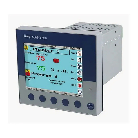
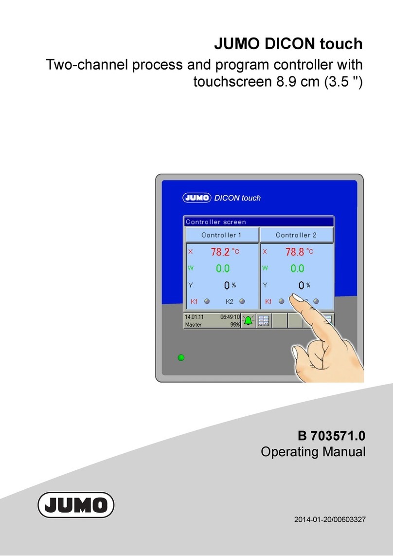
JUMO DICON touch User manual

JUMO DICON touch
Two-channel process and program controller with
paperless recorder and touchscreen 8.9 cm (3.5")
Operating Manual
70357100T90Z004K000
V1.01/EN/00603327


3
Inhalt
1 Introduction . . . . . . . . . . . . . . . . . . . . . . . . . . . . . . . . . . . . . . . . . . . . . . . . . . . . . .9
1.1 Safety information . . . . . . . . . . . . . . . . . . . . . . . . . . . . . . . . . . . . . . . . . . . . . . . . . . . . . . . . . . . . . 9
1.1.1 Warning symbols . . . . . . . . . . . . . . . . . . . . . . . . . . . . . . . . . . . . . . . . . . . . . . . . . . . . . . . . . . . . . . 9
1.1.2 Note signs . . . . . . . . . . . . . . . . . . . . . . . . . . . . . . . . . . . . . . . . . . . . . . . . . . . . . . . . . . . . . . . . . . . 9
1.1.3 Display types . . . . . . . . . . . . . . . . . . . . . . . . . . . . . . . . . . . . . . . . . . . . . . . . . . . . . . . . . . . . . . . . 10
1.2 Description . . . . . . . . . . . . . . . . . . . . . . . . . . . . . . . . . . . . . . . . . . . . . . . . . . . . . . . . . . . . . . . . . 11
1.3 Block diagram . . . . . . . . . . . . . . . . . . . . . . . . . . . . . . . . . . . . . . . . . . . . . . . . . . . . . . . . . . . . . . . 12
2 Identifying the device version . . . . . . . . . . . . . . . . . . . . . . . . . . . . . . . . . . . . . .13
2.1 Order Details . . . . . . . . . . . . . . . . . . . . . . . . . . . . . . . . . . . . . . . . . . . . . . . . . . . . . . . . . . . . . . . . 13
2.2 Scope of delivery . . . . . . . . . . . . . . . . . . . . . . . . . . . . . . . . . . . . . . . . . . . . . . . . . . . . . . . . . . . . . 15
2.3 General accessories . . . . . . . . . . . . . . . . . . . . . . . . . . . . . . . . . . . . . . . . . . . . . . . . . . . . . . . . . . 15
2.4 Accessories . . . . . . . . . . . . . . . . . . . . . . . . . . . . . . . . . . . . . . . . . . . . . . . . . . . . . . . . . . . . . . . . . 16
2.5 Nameplate . . . . . . . . . . . . . . . . . . . . . . . . . . . . . . . . . . . . . . . . . . . . . . . . . . . . . . . . . . . . . . . . . . 17
3 Mounting . . . . . . . . . . . . . . . . . . . . . . . . . . . . . . . . . . . . . . . . . . . . . . . . . . . . . . .19
3.1 Mounting site and climatic conditions . . . . . . . . . . . . . . . . . . . . . . . . . . . . . . . . . . . . . . . . . . . . . 19
3.1.1 Electrical data . . . . . . . . . . . . . . . . . . . . . . . . . . . . . . . . . . . . . . . . . . . . . . . . . . . . . . . . . . . . . . . 19
3.1.2 Environmental influences . . . . . . . . . . . . . . . . . . . . . . . . . . . . . . . . . . . . . . . . . . . . . . . . . . . . . . 19
3.1.3 Case . . . . . . . . . . . . . . . . . . . . . . . . . . . . . . . . . . . . . . . . . . . . . . . . . . . . . . . . . . . . . . . . . . . . . . 19
3.2 Dimensions . . . . . . . . . . . . . . . . . . . . . . . . . . . . . . . . . . . . . . . . . . . . . . . . . . . . . . . . . . . . . . . . . 20
3.3 Close mounting . . . . . . . . . . . . . . . . . . . . . . . . . . . . . . . . . . . . . . . . . . . . . . . . . . . . . . . . . . . . . . 21
3.4 Insertion in panel cut-out . . . . . . . . . . . . . . . . . . . . . . . . . . . . . . . . . . . . . . . . . . . . . . . . . . . . . . . 21
3.5 Care and treatment of the front cover . . . . . . . . . . . . . . . . . . . . . . . . . . . . . . . . . . . . . . . . . . . . . 21
4 Electrical connection . . . . . . . . . . . . . . . . . . . . . . . . . . . . . . . . . . . . . . . . . . . . .23
4.1 Installation notes . . . . . . . . . . . . . . . . . . . . . . . . . . . . . . . . . . . . . . . . . . . . . . . . . . . . . . . . . . . . . 23
4.1.1 Cables, shielding, and grounding . . . . . . . . . . . . . . . . . . . . . . . . . . . . . . . . . . . . . . . . . . . . . . . . 23
4.1.2 Electrical safety . . . . . . . . . . . . . . . . . . . . . . . . . . . . . . . . . . . . . . . . . . . . . . . . . . . . . . . . . . . . . . 23
4.1.3 Intended use, misuse . . . . . . . . . . . . . . . . . . . . . . . . . . . . . . . . . . . . . . . . . . . . . . . . . . . . . . . . . 24
4.2 Galvanic isolation . . . . . . . . . . . . . . . . . . . . . . . . . . . . . . . . . . . . . . . . . . . . . . . . . . . . . . . . . . . . 25
4.3 Connection diagram . . . . . . . . . . . . . . . . . . . . . . . . . . . . . . . . . . . . . . . . . . . . . . . . . . . . . . . . . . 26
4.3.1 Connection elements . . . . . . . . . . . . . . . . . . . . . . . . . . . . . . . . . . . . . . . . . . . . . . . . . . . . . . . . . . 26
4.3.2 Analog inputs . . . . . . . . . . . . . . . . . . . . . . . . . . . . . . . . . . . . . . . . . . . . . . . . . . . . . . . . . . . . . . . . 27
4.3.3 Probes for air . . . . . . . . . . . . . . . . . . . . . . . . . . . . . . . . . . . . . . . . . . . . . . . . . . . . . . . . . . . . . . . . 28
4.3.4 Probes for water and oil . . . . . . . . . . . . . . . . . . . . . . . . . . . . . . . . . . . . . . . . . . . . . . . . . . . . . . . 28
4.3.5 Probes for water and oil . . . . . . . . . . . . . . . . . . . . . . . . . . . . . . . . . . . . . . . . . . . . . . . . . . . . . . . 29
4.3.6 Probes for the operating medium water, oil, and air . . . . . . . . . . . . . . . . . . . . . . . . . . . . . . . . . . 29
4.3.7 Analog outputs . . . . . . . . . . . . . . . . . . . . . . . . . . . . . . . . . . . . . . . . . . . . . . . . . . . . . . . . . . . . . . 29
4.3.8 Digital inputs . . . . . . . . . . . . . . . . . . . . . . . . . . . . . . . . . . . . . . . . . . . . . . . . . . . . . . . . . . . . . . . . 30
4.3.9 Digital outputs . . . . . . . . . . . . . . . . . . . . . . . . . . . . . . . . . . . . . . . . . . . . . . . . . . . . . . . . . . . . . . . 30
4.3.10 Digital outputs . . . . . . . . . . . . . . . . . . . . . . . . . . . . . . . . . . . . . . . . . . . . . . . . . . . . . . . . . . . . . . . 31
4.3.11 Voltage supply (according to nameplate) . . . . . . . . . . . . . . . . . . . . . . . . . . . . . . . . . . . . . . . . . . 32

Inhalt
4
4.3.12 Interfaces . . . . . . . . . . . . . . . . . . . . . . . . . . . . . . . . . . . . . . . . . . . . . . . . . . . . . . . . . . . . . . . . . . . 33
5 Operation . . . . . . . . . . . . . . . . . . . . . . . . . . . . . . . . . . . . . . . . . . . . . . . . . . . . . . .35
5.1 Display and operating concept . . . . . . . . . . . . . . . . . . . . . . . . . . . . . . . . . . . . . . . . . . . . . . . . . . 36
5.2 Device menu . . . . . . . . . . . . . . . . . . . . . . . . . . . . . . . . . . . . . . . . . . . . . . . . . . . . . . . . . . . . . . . . 37
5.3 Alarm and event list . . . . . . . . . . . . . . . . . . . . . . . . . . . . . . . . . . . . . . . . . . . . . . . . . . . . . . . . . . . 37
5.4 Function buttons, history and channel changeover . . . . . . . . . . . . . . . . . . . . . . . . . . . . . . . . . . . 37
5.5 Images in the operating loop . . . . . . . . . . . . . . . . . . . . . . . . . . . . . . . . . . . . . . . . . . . . . . . . . . . . 38
5.5.1 Controller screen 1, Controller screen 2 and Controller overview . . . . . . . . . . . . . . . . . . . . . . . . 38
5.5.2 Program controller . . . . . . . . . . . . . . . . . . . . . . . . . . . . . . . . . . . . . . . . . . . . . . . . . . . . . . . . . . . . 40
5.5.3 General screen 1.2 . . . . . . . . . . . . . . . . . . . . . . . . . . . . . . . . . . . . . . . . . . . . . . . . . . . . . . . . . . . 41
5.5.4 Recording image . . . . . . . . . . . . . . . . . . . . . . . . . . . . . . . . . . . . . . . . . . . . . . . . . . . . . . . . . . . . . 42
5.5.5 Process screen . . . . . . . . . . . . . . . . . . . . . . . . . . . . . . . . . . . . . . . . . . . . . . . . . . . . . . . . . . . . . . 42
6 Login . . . . . . . . . . . . . . . . . . . . . . . . . . . . . . . . . . . . . . . . . . . . . . . . . . . . . . . . . . .43
6.1 Logging on . . . . . . . . . . . . . . . . . . . . . . . . . . . . . . . . . . . . . . . . . . . . . . . . . . . . . . . . . . . . . . . . . . 44
6.2 Logging out . . . . . . . . . . . . . . . . . . . . . . . . . . . . . . . . . . . . . . . . . . . . . . . . . . . . . . . . . . . . . . . . . 44
6.3 Change password . . . . . . . . . . . . . . . . . . . . . . . . . . . . . . . . . . . . . . . . . . . . . . . . . . . . . . . . . . . . 44
7 User level (Log-In) . . . . . . . . . . . . . . . . . . . . . . . . . . . . . . . . . . . . . . . . . . . . . . . .45
7.1 Example 4 Transferring controller setpoint values to the user level . . . . . . . . . . . . . . . . . . . . . . 45
8 Program administration . . . . . . . . . . . . . . . . . . . . . . . . . . . . . . . . . . . . . . . . . . .47
8.1 Enter program curves . . . . . . . . . . . . . . . . . . . . . . . . . . . . . . . . . . . . . . . . . . . . . . . . . . . . . . . . . 47
8.1.1 On the device . . . . . . . . . . . . . . . . . . . . . . . . . . . . . . . . . . . . . . . . . . . . . . . . . . . . . . . . . . . . . . . 47
8.1.2 About the setup program . . . . . . . . . . . . . . . . . . . . . . . . . . . . . . . . . . . . . . . . . . . . . . . . . . . . . . . 48
8.1.3 Section run time . . . . . . . . . . . . . . . . . . . . . . . . . . . . . . . . . . . . . . . . . . . . . . . . . . . . . . . . . . . . . 49
8.1.4 Setpoint values 1 and 2 . . . . . . . . . . . . . . . . . . . . . . . . . . . . . . . . . . . . . . . . . . . . . . . . . . . . . . . . 49
8.1.5 Operating contacts . . . . . . . . . . . . . . . . . . . . . . . . . . . . . . . . . . . . . . . . . . . . . . . . . . . . . . . . . . . 49
8.1.6 Tolerance band . . . . . . . . . . . . . . . . . . . . . . . . . . . . . . . . . . . . . . . . . . . . . . . . . . . . . . . . . . . . . . 49
8.1.7 Number of repetitions . . . . . . . . . . . . . . . . . . . . . . . . . . . . . . . . . . . . . . . . . . . . . . . . . . . . . . . . . 50
8.1.8 Start section . . . . . . . . . . . . . . . . . . . . . . . . . . . . . . . . . . . . . . . . . . . . . . . . . . . . . . . . . . . . . . . . 50
8.1.9 Parameter block . . . . . . . . . . . . . . . . . . . . . . . . . . . . . . . . . . . . . . . . . . . . . . . . . . . . . . . . . . . . . 50
9 Device information . . . . . . . . . . . . . . . . . . . . . . . . . . . . . . . . . . . . . . . . . . . . . . .51
9.1 General . . . . . . . . . . . . . . . . . . . . . . . . . . . . . . . . . . . . . . . . . . . . . . . . . . . . . . . . . . . . . . . . . . . . 51
9.1.1 Version, motherboard, Ethernet information . . . . . . . . . . . . . . . . . . . . . . . . . . . . . . . . . . . . . . . . 51
9.2 Slots . . . . . . . . . . . . . . . . . . . . . . . . . . . . . . . . . . . . . . . . . . . . . . . . . . . . . . . . . . . . . . . . . . . . . . 51
9.3 Inputs/outputs . . . . . . . . . . . . . . . . . . . . . . . . . . . . . . . . . . . . . . . . . . . . . . . . . . . . . . . . . . . . . . . 52
9.3.1 Digital and analog inputs, digital and analog outputs, external digital, and external analog inputs .
52
9.4 Functions . . . . . . . . . . . . . . . . . . . . . . . . . . . . . . . . . . . . . . . . . . . . . . . . . . . . . . . . . . . . . . . . . . . 53

5
Inhalt
9.4.1 Mathematics, logic signal, limit value outputs . . . . . . . . . . . . . . . . . . . . . . . . . . . . . . . . . . . . . . . 53
9.4.2 Timer signal, digital controller signals, control contacts, controller, analog flag, digital flag . . . . 53
9.5 Ethernet . . . . . . . . . . . . . . . . . . . . . . . . . . . . . . . . . . . . . . . . . . . . . . . . . . . . . . . . . . . . . . . . . . . . 54
9.6 PROFINET . . . . . . . . . . . . . . . . . . . . . . . . . . . . . . . . . . . . . . . . . . . . . . . . . . . . . . . . . . . . . . . . . 54
10 Functional level . . . . . . . . . . . . . . . . . . . . . . . . . . . . . . . . . . . . . . . . . . . . . . . . . .55
10.1 General . . . . . . . . . . . . . . . . . . . . . . . . . . . . . . . . . . . . . . . . . . . . . . . . . . . . . . . . . . . . . . . . . . . . 55
10.1.1 Activate functional level . . . . . . . . . . . . . . . . . . . . . . . . . . . . . . . . . . . . . . . . . . . . . . . . . . . . . . . . 55
11 Parameterization . . . . . . . . . . . . . . . . . . . . . . . . . . . . . . . . . . . . . . . . . . . . . . . . .57
11.1 Date and time . . . . . . . . . . . . . . . . . . . . . . . . . . . . . . . . . . . . . . . . . . . . . . . . . . . . . . . . . . . . . . . 57
11.2 Daylight saving time . . . . . . . . . . . . . . . . . . . . . . . . . . . . . . . . . . . . . . . . . . . . . . . . . . . . . . . . . . 57
11.3 Controller/parameter blocks . . . . . . . . . . . . . . . . . . . . . . . . . . . . . . . . . . . . . . . . . . . . . . . . . . . . 58
11.4 Setpoint values . . . . . . . . . . . . . . . . . . . . . . . . . . . . . . . . . . . . . . . . . . . . . . . . . . . . . . . . . . . . . . 62
11.4.1 Entered on the device . . . . . . . . . . . . . . . . . . . . . . . . . . . . . . . . . . . . . . . . . . . . . . . . . . . . . . . . . 63
11.4.2 Entered using the setup program . . . . . . . . . . . . . . . . . . . . . . . . . . . . . . . . . . . . . . . . . . . . . . . . 63
12 Configuration . . . . . . . . . . . . . . . . . . . . . . . . . . . . . . . . . . . . . . . . . . . . . . . . . . . .65
12.1 Analog selection . . . . . . . . . . . . . . . . . . . . . . . . . . . . . . . . . . . . . . . . . . . . . . . . . . . . . . . . . . . . . 65
12.2 Digital selector . . . . . . . . . . . . . . . . . . . . . . . . . . . . . . . . . . . . . . . . . . . . . . . . . . . . . . . . . . . . . . . 66
12.3 Basic settings . . . . . . . . . . . . . . . . . . . . . . . . . . . . . . . . . . . . . . . . . . . . . . . . . . . . . . . . . . . . . . . 71
12.4 Digital inputs IN1 to 7 . . . . . . . . . . . . . . . . . . . . . . . . . . . . . . . . . . . . . . . . . . . . . . . . . . . . . . . . . 73
12.5 Analog inputs IN8, IN9, IN10, IN11 . . . . . . . . . . . . . . . . . . . . . . . . . . . . . . . . . . . . . . . . . . . . . . . 74
12.5.1 Alarms . . . . . . . . . . . . . . . . . . . . . . . . . . . . . . . . . . . . . . . . . . . . . . . . . . . . . . . . . . . . . . . . . . . . . 77
12.6 Controller1, 2 . . . . . . . . . . . . . . . . . . . . . . . . . . . . . . . . . . . . . . . . . . . . . . . . . . . . . . . . . . . . . . . . 78
12.6.1 Controller configuration . . . . . . . . . . . . . . . . . . . . . . . . . . . . . . . . . . . . . . . . . . . . . . . . . . . . . . . . 78
12.6.2 Controller inputs . . . . . . . . . . . . . . . . . . . . . . . . . . . . . . . . . . . . . . . . . . . . . . . . . . . . . . . . . . . . . 81
12.6.3 Self-optimization controller . . . . . . . . . . . . . . . . . . . . . . . . . . . . . . . . . . . . . . . . . . . . . . . . . . . . . 83
12.6.4 Start SO on device . . . . . . . . . . . . . . . . . . . . . . . . . . . . . . . . . . . . . . . . . . . . . . . . . . . . . . . . . . . 88
12.6.5 Control loop monitoring . . . . . . . . . . . . . . . . . . . . . . . . . . . . . . . . . . . . . . . . . . . . . . . . . . . . . . . . 90
12.6.6 Output level monitoring . . . . . . . . . . . . . . . . . . . . . . . . . . . . . . . . . . . . . . . . . . . . . . . . . . . . . . . . 93
12.6.7 Controller setpoint values . . . . . . . . . . . . . . . . . . . . . . . . . . . . . . . . . . . . . . . . . . . . . . . . . . . . . . 96
12.6.8 Ramp function . . . . . . . . . . . . . . . . . . . . . . . . . . . . . . . . . . . . . . . . . . . . . . . . . . . . . . . . . . . . . . . 98
12.7 Digital outputs . . . . . . . . . . . . . . . . . . . . . . . . . . . . . . . . . . . . . . . . . . . . . . . . . . . . . . . . . . . . . . 100
12.7.1 Switch digital outputs from fixed to logic level 1 . . . . . . . . . . . . . . . . . . . . . . . . . . . . . . . . . . . . 101
12.8 Analog outputs . . . . . . . . . . . . . . . . . . . . . . . . . . . . . . . . . . . . . . . . . . . . . . . . . . . . . . . . . . . . . 102
12.9 Limit value monitoring . . . . . . . . . . . . . . . . . . . . . . . . . . . . . . . . . . . . . . . . . . . . . . . . . . . . . . . . 104
12.9.1 Function and hysteresis . . . . . . . . . . . . . . . . . . . . . . . . . . . . . . . . . . . . . . . . . . . . . . . . . . . . . . 106
12.9.2 Hysteresis . . . . . . . . . . . . . . . . . . . . . . . . . . . . . . . . . . . . . . . . . . . . . . . . . . . . . . . . . . . . . . . . . 107
12.9.3 Start-up alarm suppression . . . . . . . . . . . . . . . . . . . . . . . . . . . . . . . . . . . . . . . . . . . . . . . . . . . . 108
12.9.4 Acknowledging self-locking . . . . . . . . . . . . . . . . . . . . . . . . . . . . . . . . . . . . . . . . . . . . . . . . . . . . 108
12.9.5 Alarm . . . . . . . . . . . . . . . . . . . . . . . . . . . . . . . . . . . . . . . . . . . . . . . . . . . . . . . . . . . . . . . . . . . . . 109
12.10 Screen . . . . . . . . . . . . . . . . . . . . . . . . . . . . . . . . . . . . . . . . . . . . . . . . . . . . . . . . . . . . . . . . . . . . 110
12.10.1General configuration . . . . . . . . . . . . . . . . . . . . . . . . . . . . . . . . . . . . . . . . . . . . . . . . . . . . . . . . 110

Inhalt
6
12.10.2Configurating the screen . . . . . . . . . . . . . . . . . . . . . . . . . . . . . . . . . . . . . . . . . . . . . . . . . . . . . 111
12.10.3Start screen and watermark . . . . . . . . . . . . . . . . . . . . . . . . . . . . . . . . . . . . . . . . . . . . . . . . . . . 111
12.10.4Operating loop . . . . . . . . . . . . . . . . . . . . . . . . . . . . . . . . . . . . . . . . . . . . . . . . . . . . . . . . . . . . . 112
12.10.5Recording colors . . . . . . . . . . . . . . . . . . . . . . . . . . . . . . . . . . . . . . . . . . . . . . . . . . . . . . . . . . . . 113
12.10.6Color for controller screens 1, 2 . . . . . . . . . . . . . . . . . . . . . . . . . . . . . . . . . . . . . . . . . . . . . . . . 114
12.10.7Program controller screen . . . . . . . . . . . . . . . . . . . . . . . . . . . . . . . . . . . . . . . . . . . . . . . . . . . . 115
12.10.8General screens 1, 2 . . . . . . . . . . . . . . . . . . . . . . . . . . . . . . . . . . . . . . . . . . . . . . . . . . . . . . . . 116
12.11 Recording . . . . . . . . . . . . . . . . . . . . . . . . . . . . . . . . . . . . . . . . . . . . . . . . . . . . . . . . . . . . . . . . . 117
12.11.1Parameter . . . . . . . . . . . . . . . . . . . . . . . . . . . . . . . . . . . . . . . . . . . . . . . . . . . . . . . . . . . . . . . . . 117
12.11.2Analog channels . . . . . . . . . . . . . . . . . . . . . . . . . . . . . . . . . . . . . . . . . . . . . . . . . . . . . . . . . . . . 119
12.11.3Digital channels . . . . . . . . . . . . . . . . . . . . . . . . . . . . . . . . . . . . . . . . . . . . . . . . . . . . . . . . . . . . 119
12.12 Program controller . . . . . . . . . . . . . . . . . . . . . . . . . . . . . . . . . . . . . . . . . . . . . . . . . . . . . . . . . . . 120
12.12.1Controller signals . . . . . . . . . . . . . . . . . . . . . . . . . . . . . . . . . . . . . . . . . . . . . . . . . . . . . . . . . . . 122
12.12.2Extended functions . . . . . . . . . . . . . . . . . . . . . . . . . . . . . . . . . . . . . . . . . . . . . . . . . . . . . . . . . . 123
12.12.3Basic status . . . . . . . . . . . . . . . . . . . . . . . . . . . . . . . . . . . . . . . . . . . . . . . . . . . . . . . . . . . . . . . 124
12.12.4Manual operation mode . . . . . . . . . . . . . . . . . . . . . . . . . . . . . . . . . . . . . . . . . . . . . . . . . . . . . . 125
12.12.5Behavior for out of range parameters . . . . . . . . . . . . . . . . . . . . . . . . . . . . . . . . . . . . . . . . . . . . 126
12.12.6Weekly program . . . . . . . . . . . . . . . . . . . . . . . . . . . . . . . . . . . . . . . . . . . . . . . . . . . . . . . . . . . . 127
12.13 Timer or week-time switch . . . . . . . . . . . . . . . . . . . . . . . . . . . . . . . . . . . . . . . . . . . . . . . . . . . . . 128
12.14 Digital controller signals . . . . . . . . . . . . . . . . . . . . . . . . . . . . . . . . . . . . . . . . . . . . . . . . . . . . . . 131
12.14.1Alarms . . . . . . . . . . . . . . . . . . . . . . . . . . . . . . . . . . . . . . . . . . . . . . . . . . . . . . . . . . . . . . . . . . . 133
12.15 Mathematics/logic . . . . . . . . . . . . . . . . . . . . . . . . . . . . . . . . . . . . . . . . . . . . . . . . . . . . . . . . . . . 134
12.16 Flags/service . . . . . . . . . . . . . . . . . . . . . . . . . . . . . . . . . . . . . . . . . . . . . . . . . . . . . . . . . . . . . . . 136
12.16.1Flags . . . . . . . . . . . . . . . . . . . . . . . . . . . . . . . . . . . . . . . . . . . . . . . . . . . . . . . . . . . . . . . . . . . . . 136
12.16.2Service . . . . . . . . . . . . . . . . . . . . . . . . . . . . . . . . . . . . . . . . . . . . . . . . . . . . . . . . . . . . . . . . . . . 137
12.17 External digital inputs . . . . . . . . . . . . . . . . . . . . . . . . . . . . . . . . . . . . . . . . . . . . . . . . . . . . . . . . 138
12.18 External analog inputs . . . . . . . . . . . . . . . . . . . . . . . . . . . . . . . . . . . . . . . . . . . . . . . . . . . . . . . . 139
12.18.1Alarms . . . . . . . . . . . . . . . . . . . . . . . . . . . . . . . . . . . . . . . . . . . . . . . . . . . . . . . . . . . . . . . . . . . 140
12.19 Serial interfaces . . . . . . . . . . . . . . . . . . . . . . . . . . . . . . . . . . . . . . . . . . . . . . . . . . . . . . . . . . . . . 141
12.20 Ethernet . . . . . . . . . . . . . . . . . . . . . . . . . . . . . . . . . . . . . . . . . . . . . . . . . . . . . . . . . . . . . . . . . . . 142
12.21 Modbus TCP . . . . . . . . . . . . . . . . . . . . . . . . . . . . . . . . . . . . . . . . . . . . . . . . . . . . . . . . . . . . . . . 143
12.22 Relay module (accessories) . . . . . . . . . . . . . . . . . . . . . . . . . . . . . . . . . . . . . . . . . . . . . . . . . . . 144
12.23 PROFIBUS DP (option) . . . . . . . . . . . . . . . . . . . . . . . . . . . . . . . . . . . . . . . . . . . . . . . . . . . . . . . 145
13 Configuration – in setup program only . . . . . . . . . . . . . . . . . . . . . . . . . . . . . .147
13.1 Installing the setup program . . . . . . . . . . . . . . . . . . . . . . . . . . . . . . . . . . . . . . . . . . . . . . . . . . . 147
13.1.1 Hardware . . . . . . . . . . . . . . . . . . . . . . . . . . . . . . . . . . . . . . . . . . . . . . . . . . . . . . . . . . . . . . . . . . 147
13.1.2 Software requirements . . . . . . . . . . . . . . . . . . . . . . . . . . . . . . . . . . . . . . . . . . . . . . . . . . . . . . . 147
13.2 Starting the setup program . . . . . . . . . . . . . . . . . . . . . . . . . . . . . . . . . . . . . . . . . . . . . . . . . . . . 147
13.2.1 Establish the connection to the device . . . . . . . . . . . . . . . . . . . . . . . . . . . . . . . . . . . . . . . . . . . 148
13.2.2 Setup data transfer on or from the external mass storage device . . . . . . . . . . . . . . . . . . . . . . . 149
13.3 Connection diagram . . . . . . . . . . . . . . . . . . . . . . . . . . . . . . . . . . . . . . . . . . . . . . . . . . . . . . . . . 150
13.4 Country settings . . . . . . . . . . . . . . . . . . . . . . . . . . . . . . . . . . . . . . . . . . . . . . . . . . . . . . . . . . . . 151
13.5 User list . . . . . . . . . . . . . . . . . . . . . . . . . . . . . . . . . . . . . . . . . . . . . . . . . . . . . . . . . . . . . . . . . . . 151
13.6 User level . . . . . . . . . . . . . . . . . . . . . . . . . . . . . . . . . . . . . . . . . . . . . . . . . . . . . . . . . . . . . . . . . 152
7
Inhalt
13.7 E-mail . . . . . . . . . . . . . . . . . . . . . . . . . . . . . . . . . . . . . . . . . . . . . . . . . . . . . . . . . . . . . . . . . . . . 152
13.8 Web server . . . . . . . . . . . . . . . . . . . . . . . . . . . . . . . . . . . . . . . . . . . . . . . . . . . . . . . . . . . . . . . . 152
13.9 Modbus frames for reading . . . . . . . . . . . . . . . . . . . . . . . . . . . . . . . . . . . . . . . . . . . . . . . . . . . . 153
13.10 Modbus frames for writing . . . . . . . . . . . . . . . . . . . . . . . . . . . . . . . . . . . . . . . . . . . . . . . . . . . . . 154
13.11 PROFINET-RT . . . . . . . . . . . . . . . . . . . . . . . . . . . . . . . . . . . . . . . . . . . . . . . . . . . . . . . . . . . . . 155
13.12 Customized linearization . . . . . . . . . . . . . . . . . . . . . . . . . . . . . . . . . . . . . . . . . . . . . . . . . . . . . . 156
13.12.1Grid points . . . . . . . . . . . . . . . . . . . . . . . . . . . . . . . . . . . . . . . . . . . . . . . . . . . . . . . . . . . . . . . . 156
13.12.2Formula . . . . . . . . . . . . . . . . . . . . . . . . . . . . . . . . . . . . . . . . . . . . . . . . . . . . . . . . . . . . . . . . . . 157
13.13 Process screen . . . . . . . . . . . . . . . . . . . . . . . . . . . . . . . . . . . . . . . . . . . . . . . . . . . . . . . . . . . . . 159
13.13.1process screen editor . . . . . . . . . . . . . . . . . . . . . . . . . . . . . . . . . . . . . . . . . . . . . . . . . . . . . . . . 160
13.13.2Background . . . . . . . . . . . . . . . . . . . . . . . . . . . . . . . . . . . . . . . . . . . . . . . . . . . . . . . . . . . . . . . 161
13.13.3Signal types for process screens (overview) . . . . . . . . . . . . . . . . . . . . . . . . . . . . . . . . . . . . . . 163
13.13.4General object features . . . . . . . . . . . . . . . . . . . . . . . . . . . . . . . . . . . . . . . . . . . . . . . . . . . . . . 164
13.13.5Preview screen . . . . . . . . . . . . . . . . . . . . . . . . . . . . . . . . . . . . . . . . . . . . . . . . . . . . . . . . . . . . . 165
13.13.6Transfer process screen to device . . . . . . . . . . . . . . . . . . . . . . . . . . . . . . . . . . . . . . . . . . . . . . 166
14 Special functions . . . . . . . . . . . . . . . . . . . . . . . . . . . . . . . . . . . . . . . . . . . . . . . .167
14.1 Calibrating the touchscreen . . . . . . . . . . . . . . . . . . . . . . . . . . . . . . . . . . . . . . . . . . . . . . . . . . . . 167
15 Online parameter . . . . . . . . . . . . . . . . . . . . . . . . . . . . . . . . . . . . . . . . . . . . . . . .169
15.1 Fine Adjustment . . . . . . . . . . . . . . . . . . . . . . . . . . . . . . . . . . . . . . . . . . . . . . . . . . . . . . . . . . . . 169
15.2 Ethernet (option) . . . . . . . . . . . . . . . . . . . . . . . . . . . . . . . . . . . . . . . . . . . . . . . . . . . . . . . . . . . . 171
15.3 Date and time . . . . . . . . . . . . . . . . . . . . . . . . . . . . . . . . . . . . . . . . . . . . . . . . . . . . . . . . . . . . . . 172
15.4 Screenshot . . . . . . . . . . . . . . . . . . . . . . . . . . . . . . . . . . . . . . . . . . . . . . . . . . . . . . . . . . . . . . . . 172
15.5 Deleting measurement data memory . . . . . . . . . . . . . . . . . . . . . . . . . . . . . . . . . . . . . . . . . . . . 172
15.6 Approval of extra codes . . . . . . . . . . . . . . . . . . . . . . . . . . . . . . . . . . . . . . . . . . . . . . . . . . . . . . . 173
15.7 Testing calibration . . . . . . . . . . . . . . . . . . . . . . . . . . . . . . . . . . . . . . . . . . . . . . . . . . . . . . . . . . . 174
15.8 Various process values . . . . . . . . . . . . . . . . . . . . . . . . . . . . . . . . . . . . . . . . . . . . . . . . . . . . . . . 174
15.9 Startup program . . . . . . . . . . . . . . . . . . . . . . . . . . . . . . . . . . . . . . . . . . . . . . . . . . . . . . . . . . . . 175
16 Error and alarm messages . . . . . . . . . . . . . . . . . . . . . . . . . . . . . . . . . . . . . . . .177
16.1 Error messages in float values and on the display . . . . . . . . . . . . . . . . . . . . . . . . . . . . . . . . . . 177
16.2 Display of error messages for binary values . . . . . . . . . . . . . . . . . . . . . . . . . . . . . . . . . . . . . . . 177
17 Retrofitting optional boards . . . . . . . . . . . . . . . . . . . . . . . . . . . . . . . . . . . . . . .179
17.1 Safety information . . . . . . . . . . . . . . . . . . . . . . . . . . . . . . . . . . . . . . . . . . . . . . . . . . . . . . . . . . . 179
17.2 Identifying the modules . . . . . . . . . . . . . . . . . . . . . . . . . . . . . . . . . . . . . . . . . . . . . . . . . . . . . . . 179
17.3 Installing modules . . . . . . . . . . . . . . . . . . . . . . . . . . . . . . . . . . . . . . . . . . . . . . . . . . . . . . . . . . . 180
17.3.1 Accessories . . . . . . . . . . . . . . . . . . . . . . . . . . . . . . . . . . . . . . . . . . . . . . . . . . . . . . . . . . . . . . . . 182
18 Approvals / approval marks . . . . . . . . . . . . . . . . . . . . . . . . . . . . . . . . . . . . . . .175
18.1 UL . . . . . . . . . . . . . . . . . . . . . . . . . . . . . . . . . . . . . . . . . . . . . . . . . . . . . . . . . . . . . . . . . . . . . . . 175

Inhalt
8
18.2 GL . . . . . . . . . . . . . . . . . . . . . . . . . . . . . . . . . . . . . . . . . . . . . . . . . . . . . . . . . . . . . . . . . . . . . . . 176
18.3 DIN . . . . . . . . . . . . . . . . . . . . . . . . . . . . . . . . . . . . . . . . . . . . . . . . . . . . . . . . . . . . . . . . . . . . . . 179
19 China RoHS . . . . . . . . . . . . . . . . . . . . . . . . . . . . . . . . . . . . . . . . . . . . . . . . . . . .181
19.1 Certificate . . . . . . . . . . . . . . . . . . . . . . . . . . . . . . . . . . . . . . . . . . . . . . . . . . . . . . . . . . . . . . . . . 181

9
1 Introduction
1.1 Safety information
General information
This manual contains information that must be observed in the interest of your own safety and
to avoid damage to assets. This information is supported by symbols which are used in this
manual as indicated.
Please read this manual before commissioning the device. Keep the manual in a place acces-
sible to all users at all times.
If difficulties occur during commissioning please refrain from carrying out any manipulations
that could jeopardize your warranty rights.
1.1.1 Warning symbols
1.1.2 Note signs
DANGER!
This symbol indicates that personal injury caused by electrical shock may occur if the re-
spective precautionary measures are not carried out.
WARNING!
This symbol in connection with the signal word indicates that personal injury may occur if the
respective precautionary measures are not carried out.
CAUTION!
This symbol in connection with the signal word indicates that damage to assets or data loss
will occur if the respective precautionary measures are not taken.
CAUTION!
This symbol indicates that components could be destroyed by electrostatic discharge
(ESD = Electro Static Discharge) if the respective cautionary measures are not taken.
Only use the ESD packages intended for this purpose to return device inserts, assembly
groups, or assembly components.
READ DOCUMENTATION!
This symbol – placed on the device – indicates that the associated device documentation
has to be observed. This is necessary to recognize the kind of the potential hazards as
well as the measures to avoid them.
NOTE!
This symbol refers to important information about the product, its handling, or additional
use.
REFERENCE!
This symbol refers to further information in other sections, chapters, or manuals.

1 Introduction
10
1.1.3 Display types
Menu structure
The > symbol between words indicates a menu structure and enables the parameters to be
quickly detected in the configuration level or for navigation in the setup program, such as the
software version of the devices, for example:
DEVICE MENU >GENERAL >VERSION >SWVERSION
Active input
The device has no buttons and is operated using a finger or a pen.
The following instructions will therefore make references to "touching" and the images dis-
played will show a hand operating the device.
FURTHER INFORMATION!
This symbol is used in the tables and refers to further information in connection with the
table.
&
DISPOSAL!
This device and the batteries (if installed) must not be disposed in the garbage can after
use! Please ensure that they are disposed properly and in an environmentally friendly
manner.

11
1 Introduction
1.2 Description
The DICON touch is a two-channel universal process and program controller that displays in-
formation on a vibrant screen. The device is easy to operate via a touchscreen.
Both control channels use the tried-and-tested JUMO control algorithm with two possible opti-
mization options. These enable a simple and highly-accurate startup. It also enables multiple
zone control, cascade control, or other complex control tasks.
The block diagram below illustrates the various different hardware options offered by the mod-
ular hardware concept. Four analog universal inputs and up to eight external inputs can record
a variety of physical measured values with high precision. The actuators can be controlled di-
rectly in the device with either an analog or digital setup. These can be expanded further
through external digital outputs. Interfaces such as Modbus (master/slave), PROFIBUS, PRO-
FINET-RT Class B or Ethernet with Web server can be used for the communication with higher-
order systems.
To ensure secure process operation, the device has a password-protected user administration
with individual assignment of rights for different levels or control commands. Screen masks for
controllers, program generators, recording, and for overview screens are ready-made and
available. An individual process screen can be created using the configuration software. Using
the extra-code recording function, important analog and digital process values can be saved so
that they are tamper-proof, so that they can be graphically visualized, and so that they can be
exported via interface or USB stick in a tamper-proof fashion to the PC.
The configuration software ensures that the process controller can be easily programmed, that
math or logical coherences can be described, and that customer-specific linearizations can be
created. In addition, tools for simulating external signals or control paths are included. These
tools can also record for the duration of the startup.
A comprehensive alarm and limit-value concept as well as a flexible digital signal administration
complete the "all-in-one" device.

1 Introduction
12
1.3 Block diagram
Analog input ( In8universal)
Analog input (universal) In10
Relay output OUT1
(changeover contact)
703571
8 expansion slots
Voltage supply
- AC 110 to 240 V, +10/-15 %
- AC/DC 24 V, +30/-25 %
Interface RS485)
Modbus master or slave
COM1 (
Relay output OUT2
(changeover contact)
Digital/analog outputs
OUT4
OUT3
Digital/analog outputs
OUT6
OUT5
Digital/analog outputs
OUT8
OUT7
Digital/analog outputs
OUT10
OUT9
Digital/analog outputs
OUT12
OUT11
Interface COM2 (
Modbus master or slave,
PROFIBUS-DP or PROFINET device
RS422/485)
Ethernet
USB interfaces
- USB device
- USB host
Available ex-works
Option
7 In1 to 7
(potential free contact)
Digital inputs
Analog input (universal) In9
Analog input (universal) In11

13
2 Identifying the device version
2.1 Order Details
(1) Basic type
703571 JUMO DICON touch - two-channel process and program controller with RS485 interface
(2) Version
8 Standard with default settings
9 Customer-specific configuration (specifications in plain text)
(3) National language of display texts
01 German
02 English
03 French
(4) Input IN10
00 Not used
10 Analog input (universal)
(5) Input IN11
00 Not used
10 Analog input (universal)
(6) Outputs OUT3/4
00 None
11 1 relay (changeover contact)
12 2 relays (make contact)
13 1 solid-state relay 230 V, 1 A
14 1 logic output 0/22 V, max. 30 mA
15 2 logic outputs 0/12 V, 20 mA
16 1 analog output
17 Two PhotoMOS® relays1
20 2 solid state relay 230 V, 1 A for motor actuator drives (double slot:OUT3/4 and OUT7/8)
(7) Outputs OUT5/6
00 None
11 1 relay (changeover contact)
12 2 relays (make contact)
13 1 solid-state relay 230 V, 1 A
14 1 logic output 0/22 V, max. 30 mA
15 2 logic outputs 0/12 V, 20 mA
16 1 analog output
17 2 PhotoMOS® relays
20 2 solid state relay 230 V, 1 A for motor actuator drives (double slot:OUT5/6 and OUT9/10)
(8) Outputs OUT7/8 (not available for assignment with module 20 on OUT3/4)
00 None

2 Identifying the device version
14
11 1 relay (changeover contact)
12 2 relays (make contact)
13 1 solid-state relay 230 V, 1 A
14 1 logic output 0/22 V, max. 30 mA
15 2 logic outputs 0/12 V, 20 mA
16 1 analog output
17 2 PhotoMOS® relays
(9) Outputs OUT9/10 (not available for assignment with module 20 on OUT5/6)
00 None
11 1 relay (changeover contact)
12 2 relays (make contact)
13 1 solid-state relay 230 V, 1 A
14 1 logic output 0/22 V, max. 30 mA
15 2 logic outputs 0/12 V, 20 mA
16 1 analog output
17 2 PhotoMOS® relays
(10) Outputs OUT11/12
00 None
11 1 relay (changeover contact)
12 2 relays (make contact)
13 1 solid-state relay 230 V, 1 A
14 1 logic output 0/22 V, max. 30 mA
15 2 logic outputs 0/12 V, 20 mA
16 1 analog output
17 2 PhotoMOS® relays
(11) Voltage supply
23 AC 110 ... 240 V +10/-15 %, 48 ... 63 Hz
39 AC/DC 24 V +30/-25 %, 48 ... 63 Hz
(12) COM2 interface
00 Not used
08 Ethernet
54 RS422/485 Modbus RTU
63 PROFINET2
64 PROFIBUS-DP
(13) DIN-tested
000 Without approval
056 With DIN approval
(14) GL-tested
000 Without approval
062 With GL approval

15
2 Identifying the device version
2.2 Scope of delivery
• 1 controller in the ordered version
• 1 Operating Manual
• 1 panel seal 4 retaining elements for panel installation
2.3 General accessories
(15) Extra code
000 None
213 Recording function
214 Math and logic module
223 Program controller
879 AMS2750/CQI-93
1PhotoMOS is a registered trademark of Panasonic Corporation
2In connection with PROFINET no GL and DIN approval
3For the calibration certificate the channels to be checked are to be defined with the thermocouple type and the de-
sired measuring points.
(1) /(2) -(3) -(4) (5) -(6) (7) (8) (9) (10) -(11) -(12) /(13) ,(14) ,(15)
Order code /-- - - - / , , ,
...1
Order exam-
ple
703571/X-X-XX-XXXX X-X-X/X,X,X
1List extra codes in sequence and separate using commas.
Article Part no.
Program editor/startup 00607139
Setup/program editor 00606496
PCA3000/PCC JUMO software package 709701/709702 00431884
USB cable A-connector mini B-connector 3 m 00506252

2 Identifying the device version
16
2.4 Accessories
Item Parts no.
Modules for expansion slots:
One analog input (universal) 00581159
One relay output (changeover contact) 00581160
Two relay outputs (N/O contact) 00581162
One logic output DC 0/22 V, max. 30 mA 00581165
Two logic outputs DC 0/12 V max. 20 mA 00581168
One solid state relay AC 230 V, 1 A 00581164
Two solid state relays AC 230 V, 1 A for
motor actuator
00621574
Two PhotoMOS® relays1
DC 45 V, max. 200 mA,
AC 30 V, max. 200 mA
00581171
One analog output (universal) 00581169
Ethernet interface 00581174
Serial interface RS422/RS485 00581172
PROFIBUS-DP interface 00581173
1PhotoMOS is a registered trademark of Panasonic Corporation

17
2 Identifying the device version
2.5 Nameplate
Position
The nameplate is affixed to the case.
Contents
The nameplates contain important information. This includes:
Device type (Typ)
Compare the specifications on the nameplate with the order.
Identify the supplied device version using the order details (order code).
Part no. (TN)
The part no. uniquely identifies an article in the catalog. It is important for communication be-
tween the customer and the sales department.
Fabrication number (F-No.:)
Among other things, the fabrication number contains the date of production (year/week).
Example: F-No. = 1234567801013010000
The characters in question are digits 12, 13, 14, and 15 (from the left).
The device was therefore produced in the 1st calendar week of 2013.
Identifying the optional modules
The device type also contains information about optional default modules, as in the following
example of the Ethernet interface (Figure 08):
703571/8-01-00-00-00-00-00-00-00-25-08... (see type key)
Further information on identifying optional modules is included in this chapter:
ÖB 703571.0 - Chapter 9.2 "Slots", Page 51
Description Designation on the nameplate
Device type (A) Type
Voltage supply, power consumption (B)
Fabrication number (C) F-No.
Part no. (D) TN

2 Identifying the device version
18

19
3 Mounting
3.1 Mounting site and climatic conditions
The mounting site should be free from vibration, dust and corrosive media. Install controllers
as far away as possible from sources of electromagnetic fields, such as those created by fre-
quency converters or high-voltage ignition transformers. Conditions at the mounting site must
correspond to the following environmental influences:
3.1.1 Electrical data
3.1.2 Environmental influences
3.1.3 Case
Voltage supply
Connection
Voltage
At the back via screw terminals
AC/DC 24 V +30/-25%, 48 to 63 Hz or AC 110 to 240 V +10/-15 %,
48 to 63 Hz
Power consumption At voltage supply 230 V: max. 15 VA / 7 W
At voltage supply 24 V: max. 12 VA / 9 W
Inputs and outputs
Connection
Conductor cross section
At the back via screw terminals
Max. 2.5 mm 2, wire or strand with end sleeve
Electrical safety According to DIN EN 61010-1
Overvoltage category III, pollution degree 2
Electromagnetic compatibility
Interference emission
Interference immunity
According to DIN EN 61326-1
Class A - For industrial applications only
Industrial requirements
Memory data recorder Memory cycle Recording interval
When recording:
4 analog signals
3 digital signals
1 s approx. 44 days
5 s approx. 220 days
10 s approx. 441 days
60 s approx. 2646 days (7 years, 91 days)
Ambient/storage temperature range -5 to +55 °C/-30 to +70 °C
Resistance to climatic conditions Humidity 3K3 (DIN EN 60721-3-3) with extended temperature
range,
rel. humidity ≤95 % mid-year without condensation
Site Altitude maximum 2000m above sea level
Case type Plastic front frame with metal case barrel (for indoor use only)
Front frame dimensions 96 mm × 96 mm
Panel cut-out 92+0.8 mm × 92+0.8 mm according to DIN IEC 61554
Close mounting Spacing between the panel cut-outs, min. 35 mm horizontally and
min. 80 mm vertically

3 Mounting
20
3.2 Dimensions
Panel thickness Max. 5 mm
Depth behind panel Max. 130 mm
Mounting Four mounting brackets
Operating position
(including the viewing angle of the TFT color
screen)
Any
Horizontal ±65°, vertical +40 to -65°
Protection type Front IP66, rear IP20, according to DIN EN 60529
Weight (fully fitted) approx. 1000 g
(20) USB host interface (21) USB device interface for setup
(22) Panel cut-out
92 +0.8
92
+0.8
(22)
(20) (21)
130.9 - panel thickness
Panel thickness
Other manuals for DICON touch
5
Table of contents
Other JUMO Controllers manuals

JUMO
JUMO dTRANS pH 02 User manual

JUMO
JUMO TYA S201 User manual

JUMO
JUMO diraTRON Series User manual

JUMO
JUMO DICON 400 User manual

JUMO
JUMO DICON 401 User manual

JUMO
JUMO TYA 202 User manual

JUMO
JUMO AQUIS 500 RS User manual

JUMO
JUMO IMAGO F3000 User manual

JUMO
JUMO cTRON 04 User manual

JUMO
JUMO AQUIS 500 pH User manual

JUMO
JUMO iTRON04 User manual

JUMO
JUMO 709062/8-01-50 User manual

JUMO
JUMO IMAGO F3000 User manual

JUMO
JUMO B 703571.0 User manual

JUMO
JUMO IMAGO 500 User manual

JUMO
JUMO dTRON 304 User manual

JUMO
JUMO DICON touch User manual

JUMO
JUMO AQUIS 500 RS User manual

JUMO
JUMO diraTRON 104 User manual

JUMO
JUMO dTRON 304 User manual