LPRS ERA900TRS User manual

eRA900TRS (PCB Rev 3.10)
Doc Version 1.0
easyRadio Advanced
User Guide
Modules Included:
•
ERA900TRS
o
804MHz – 940MHz
CC ID: SLW-ERA9TRS
Low Power Radio Solutions Ltd
Doc Version 1.0
easyRadio Advanced
User Guide
Low Power Radio Solutions Ltd
Station Lane
Witney OXON
OX28 4BH
http://www.lprs.co.uk
Page 1 of 18
easyRadio Advanced

eRA900TRS (PCB Rev 3.10)
Doc Version 1.0
Table of Contents
Changes to this document
................................
Terms and Conditions of Use
................................
CC Warning Statement:
................................
Introduction to easyRadio Advanced
eatures: ................................
.......................
Basic Specifications
................................
ERA900TRS Transceiver Description
easyRadio Transceiver
................................
Block Diagram
................................
Physical Dimensions
................................
Pin Description (easyRadio mode)
Checklist ................................
............................
Application & Operation of a transceiver:
ERAx00TRS ................................
............................
Typical System Block Diagram
..........................
Absolute Maximum Ratings
................................
Performa
nce Data: ERAxxxTRS Supply +5.0 Volt
± 5%, Temperature 20° C
................................
ERA900TRS Channel requencies vs Bandwidth
Settings ................................
...............................
Low Power Radio Solutions Ltd
Doc Version 1.0
................................
.... 3
................................
3
................................
...... 4
Introduction to easyRadio Advanced
................... 5
.......................
5
................................
....... 5
..................... 6
................................
...... 6
................................
............... 6
................................
..... 6
Pin Description (easyRadio mode)
................... 7
............................
7
Application & Operation of a transceiver:
............................
9
..........................
9
................................
10
nce Data: ERAxxxTRS Supply +5.0 Volt
................................
10
ERA900TRS Channel requencies vs Bandwidth
...............................
11
easyRadio Configuration Command Set
RS232 Communication Settings
R Channel Settings
................................
RSSI
................................
RSSI Levels (804MHz –
940MHz)
PCB Layout
................................
Power Supply
................................
Antennas
................................
Product Order Codes
................................
easy-
Radio Advanced Module irmware Version
................................
................................
Document History
................................
Copyright
................................
Disclaimer
................................
Contact Information
................................
Low Power Radio Solutions Ltd
Station Lane
Witney OXON
OX28 4BH
http://www.lprs.co.uk
Page 2 of 18
easyRadio Configuration Command Set
............ 12
RS232 Communication Settings
................. 12
................................
... 13
................................
................................ 15
940MHz)
................... 15
................................
..................... 16
................................
................. 16
................................
........................ 16
................................
......... 16
Radio Advanced Module irmware Version
................................
........... 16
................................
.............. 17
................................
........................... 18
................................
.......................... 18
................................
.......... 18

eRA900TRS (PCB Rev 3.10)
Doc Version 1.0
Changes to this document
This data sheet has been updated to reflect firmware changes throughout the range of modules.
are recorded in the documentation history later in the document.
Terms and Conditions of Use
Low Power Radio Solutions Ltd
has an on
therefore reserve the r
ight to make changes without notice. The information contained in this data sheet is believed
to be accurate however
we do not assume any responsibility for errors or any liability arising from the application or
use of any product or circuit described her
including fitness for any particular application.
e
asyRadio modules are a component part of an end system product and should be treated as such. Testing to fitness is
the sole responsibi
lity of the manufacturer of the device into which easyRadio products are fitted, and is expected
BE ORE deployment into the field.
Any liability rom de ect or mal unction is limited to the replacement o product ONLY, and does not include labour
or other incurred corrective expenses.
Using or continuing to use these devices hereby binds the user to these terms.
Low Power Radio Solutions Ltd
Doc Version 1.0
Changes to this document
This data sheet has been updated to reflect firmware changes throughout the range of modules.
are recorded in the documentation history later in the document.
Terms and Conditions of Use
has an on
-
going policy to improve the performance and reliability of their products; we
ight to make changes without notice. The information contained in this data sheet is believed
we do not assume any responsibility for errors or any liability arising from the application or
use of any product or circuit described her
ein
. This data sheet neither states nor implies warranty of any kind,
including fitness for any particular application.
asyRadio modules are a component part of an end system product and should be treated as such. Testing to fitness is
lity of the manufacturer of the device into which easyRadio products are fitted, and is expected
Any liability rom de ect or mal unction is limited to the replacement o product ONLY, and does not include labour
Using or continuing to use these devices hereby binds the user to these terms.
Low Power Radio Solutions Ltd
Station Lane
Witney OXON
OX28 4BH
http://www.lprs.co.uk
Page 3 of 18
This data sheet has been updated to reflect firmware changes throughout the range of modules.
Specific alterations
going policy to improve the performance and reliability of their products; we
ight to make changes without notice. The information contained in this data sheet is believed
we do not assume any responsibility for errors or any liability arising from the application or
. This data sheet neither states nor implies warranty of any kind,
asyRadio modules are a component part of an end system product and should be treated as such. Testing to fitness is
lity of the manufacturer of the device into which easyRadio products are fitted, and is expected
Any liability rom de ect or mal unction is limited to the replacement o product ONLY, and does not include labour

easyRadio Advanced Radio Modules (Rev 3.6)
FCC Warning Statement:
•This
device complies with Part 15 of the CC Rules.
Operation is subject to the following two conditions:
(1) This device may
not cause harmful interference, and
(2)
This device must accept any interference received, including interference that may cause und
sired operation.
•
This equipment complies with CC radiation exposure limits set forth for an uncontrolled enviro
ment. End user
s must follow the specific operating instructions for satisfying R exposure compl
ance. This transmitter must not be co
transmitter. T
his device should not be used with antennas other than those
those of less or
equal gain to the maximum gain used in the table below.
•
Changes or modifications not expressly approved by the party responsible for compliance could
void the user’s authority to operate the equipment.
•
Pin 1.
Not suita
ble for use for CC compliance. or CC compliance, this pin MUST be cut off prior
to installation
Antennas Approved to use with ERA900TRS
Supplier
LPRS
LPRS
LPRS
Antennas must be used in conjunction with U L cable or
LPRS Part#: ARW-CAB-SMA-
UFL
easyRadio Advanced Radio Modules (Rev 3.6)
device complies with Part 15 of the CC Rules.
Operation is subject to the following two conditions:
not cause harmful interference, and
This device must accept any interference received, including interference that may cause und
This equipment complies with CC radiation exposure limits set forth for an uncontrolled enviro
s must follow the specific operating instructions for satisfying R exposure compl
ance. This transmitter must not be co
-
located or operated in conjunction with any other antenna or
his device should not be used with antennas other than those
equal gain to the maximum gain used in the table below.
Changes or modifications not expressly approved by the party responsible for compliance could
void the user’s authority to operate the equipment.
ble for use for CC compliance. or CC compliance, this pin MUST be cut off prior
Antennas Approved to use with ERA900TRS
Part Number
Gain
ANT900MS
3dBi
ANT
-
WP915SMA
-
Y
2.5dBi
ANT
-
RP915SMA
-
Y
2dBi
Antennas must be used in conjunction with U L cable or
equivalent:
UFL
-10
Page 4 of 18
This device must accept any interference received, including interference that may cause und
e-
This equipment complies with CC radiation exposure limits set forth for an uncontrolled enviro
n-
s must follow the specific operating instructions for satisfying R exposure compl
i-
located or operated in conjunction with any other antenna or
specified below or
Changes or modifications not expressly approved by the party responsible for compliance could
ble for use for CC compliance. or CC compliance, this pin MUST be cut off prior

eRA900TRS (PCB Rev 3.10) Doc Version 1.0
Introduction to easyRadio Advanced
easyRadio Advanced (ERA) modules extend on the
simplicity of previous easyRadio(02) modules by
incor
porating truly innovative features, including
the ability to change
bandwidth of the radio from
150
KHz down to 12.5KHz, which means narrow
band performance on a wide-
band budget.
Internal temperature measurement ensures less than
1.5KHz frequency drift fro
m ambient 20°C, over a range
of -
40°C to +85°C, as well as providing a usable
thermometer for the connected application accurate to
within 1°C.
Modes of transmission include an enhanced easyRadio
protocol with 16-
bit encryption and anti
software
, plus raw data modes where users can now use
self-
coding system which can be set to interface to any
other raw data module on ISM bands in both SK ( M)
and ASK (AM) modulation.
With the addition of three (total 4) separate data buffers,
data throughput has been m
assively improved by around
25% (Using equivalent BAUD rate).
eRA900TRS (PCB Rev 3.10) Doc Version 1.0
Page 5 of 18
Introduction to easyRadio Advanced
easyRadio Advanced (ERA) modules extend on the
simplicity of previous easyRadio(02) modules by
porating truly innovative features, including
bandwidth of the radio from
KHz down to 12.5KHz, which means narrow
-
band budget.
Internal temperature measurement ensures less than
m ambient 20°C, over a range
40°C to +85°C, as well as providing a usable
thermometer for the connected application accurate to
Modes of transmission include an enhanced easyRadio
bit encryption and anti
-cross talk
, plus raw data modes where users can now use
coding system which can be set to interface to any
other raw data module on ISM bands in both SK ( M)
With the addition of three (total 4) separate data buffers,
assively improved by around
Features:
•
A digital RSSI (Received Signal Strength Indication)
now reduces the requirement for the host to handle
A-
D measurement and can be called via a simple
command for
either the current RSSI level or the
signal strength of the last received data packet. This
value can also be delivered as the first BYTE in the
delivered packet.
•
Temporary channel/power level selection:
command
allows the user to scan other channels on
the fly without storing the settings in internal
EEPROM, therefore not reducing the life of the
EEPROM through repetitive modification.
•
ree flash firmware upgrades.
LPRS, new updates/features
programmed making a truly future proof solution.
Custom firmware can also be used (Contact LPRS for
details)
•Back compatibility with
easyRadio
modules.
•
Temperature compensation plus c
synthesiser for frequency acc
1KHz over full temperature range
•
Temperature sensor usable by host
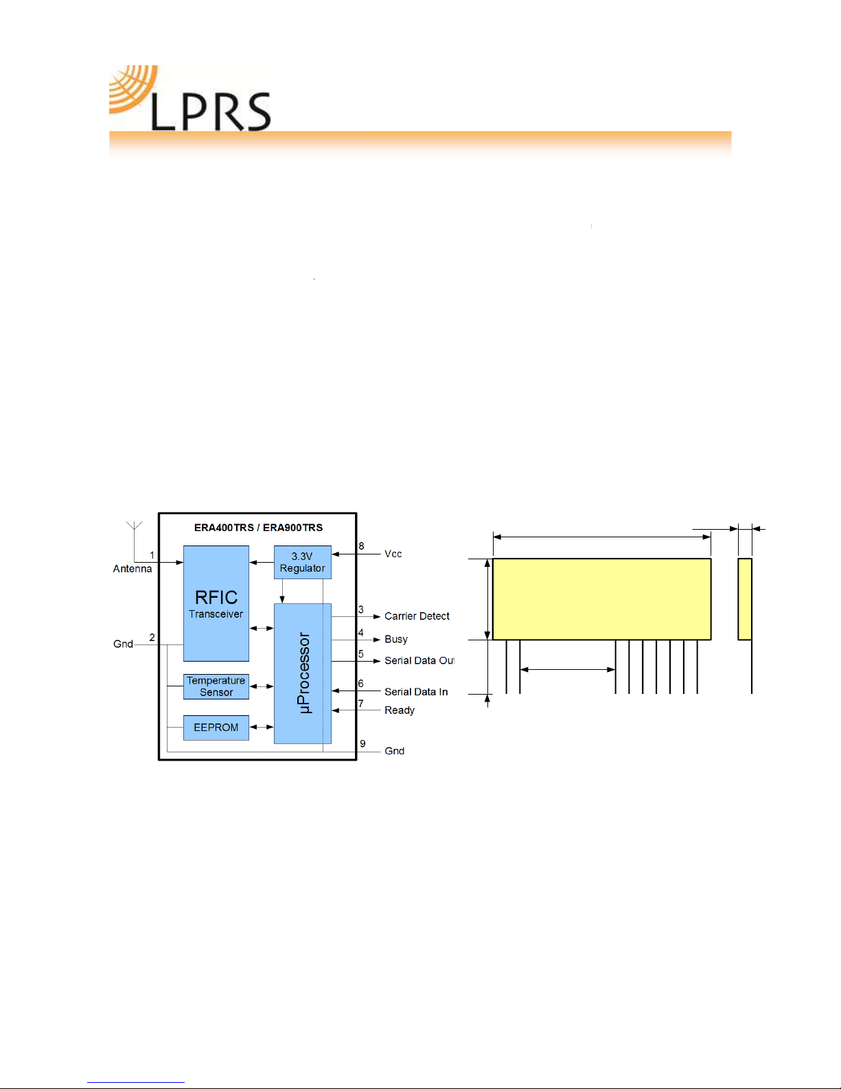
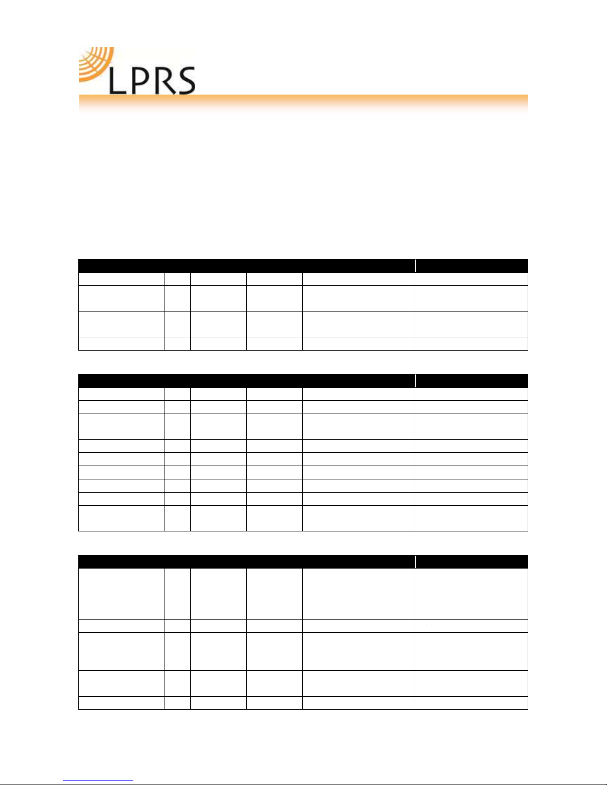
Basic S ecifications
High sensitivity receiver
-107dBm @ 19.2 Kbps
-112dBm @ 4.8 Kbps
-117dBm @ 2.4 Kbps
Current
Receiver: 21mA
(Max)
Transmitter: 32mA
(Max)
User Programmable:
requency (Up to 132 channels)
Bandwidth (Down to 12.5KHz)
RS232 Data Rate 2.4Kbps –
115.2Kbps
Output Power (Up to 10dBm)
10mW
(ERA400TRS & ERA400TS)
5mW (ERA900TRS & ERA900TS)
Page 5 of 18
A digital RSSI (Received Signal Strength Indication)
now reduces the requirement for the host to handle
D measurement and can be called via a simple
either the current RSSI level or the
signal strength of the last received data packet. This
value can also be delivered as the first BYTE in the
Temporary channel/power level selection:
This
allows the user to scan other channels on
the fly without storing the settings in internal
EEPROM, therefore not reducing the life of the
EEPROM through repetitive modification.
ree flash firmware upgrades.
Using the tools from
LPRS, new updates/features
can be quickly
programmed making a truly future proof solution.
Custom firmware can also be used (Contact LPRS for
easyRadio
02 series
Temperature compensation plus c
rystal controlled
synthesiser for frequency acc
uracy less than +/-
1KHz over full temperature range
Temperature sensor usable by host
(Max)
(Max)
requency (Up to 132 channels)
Bandwidth (Down to 12.5KHz)
115.2Kbps
Output Power (Up to 10dBm)
(ERA400TRS & ERA400TS)
5mW (ERA900TRS & ERA900TS)

eRA900TRS (PCB Rev 3.10) Doc Version 1.0
ERA900TRS
Transceiver Descri tion
The easy
Radio Transceiver is a complete sub
transceiver, a microcontroller and a
The Serial Data Input and Serial Data Output operate at the standard 19,200 Baud and the two
lines provide optional flow control to and from the host. The easyRadio Transceiver can accept and tran
mit up to 180 bytes of data, which it buffers internally before transmitting in an efficient over
mat.
Any other easyRadio Transce
iver within range and on the same channel that ‘hears’ the transmission will
decode the message and place the recovered data within a receive buffer that can then be downloaded to
the receiving host for processing and interpretation. Radio transmission and
duplex) i.e. transmit OR receive but not simultaneously.
Increased internal buffers however, allow the user to upload while a download is in progress giving an a
pearance of fully duplex data flow.
easyRadio Transceiver
Block Diagram
eRA900TRS (PCB Rev 3.10) Doc Version 1.0
Page 6 of 18
Transceiver Descri tion
Radio Transceiver is a complete sub
-
system that combines a high performance very low power R
transceiver, a microcontroller and a
voltage regulator.
The Serial Data Input and Serial Data Output operate at the standard 19,200 Baud and the two
lines provide optional flow control to and from the host. The easyRadio Transceiver can accept and tran
mit up to 180 bytes of data, which it buffers internally before transmitting in an efficient over
iver within range and on the same channel that ‘hears’ the transmission will
decode the message and place the recovered data within a receive buffer that can then be downloaded to
the receiving host for processing and interpretation. Radio transmission and
reception is bi
duplex) i.e. transmit OR receive but not simultaneously.
Increased internal buffers however, allow the user to upload while a download is in progress giving an a
Physical Dimensions
ERA400TRS
ERA900TRS
Pin Pitch 2.54mm
PCB Hole Size 1.0mm
1 2
38.0 mm
14.0 mm10.0 mm
15.24 mm
Page 6 of 18
system that combines a high performance very low power R
The Serial Data Input and Serial Data Output operate at the standard 19,200 Baud and the two
handshake
lines provide optional flow control to and from the host. The easyRadio Transceiver can accept and tran
s-
mit up to 180 bytes of data, which it buffers internally before transmitting in an efficient over
-air code for-
iver within range and on the same channel that ‘hears’ the transmission will
decode the message and place the recovered data within a receive buffer that can then be downloaded to
reception is bi
-directional (half
Increased internal buffers however, allow the user to upload while a download is in progress giving an a
p-
Physical Dimensions
ERA400TRS
ERA900TRS
Pin Pitch 2.54mm
PCB Hole Size 1.0mm
3 4 5 6 7 8 9
38.0 mm
15.24 mm
4.0 mm

eRA900TRS (PCB Rev 3.10) Doc Version 1.0
Pin Descri tion (
easyRadio
Pin No
Name
1
Antenna
2
R Ground
3
CD
4
Busy Output
5
Serial Data Out
6
Serial Data In
7
Host Ready Input
8
Vcc
9
Ground
Checklist
•
The module operates internally from an on board 3.3 Volt low drop regulator. The logic levels of
the input/output pins are therefore between 0 Volt and 3.3 Volts. (See specifications/performance
data).
•
The serial inputs and output
vice. Do not connect any of the inputs or outputs directly to an RS232 port. The transceiver module
may be permanently damaged by the voltages (+/
tion Circuit ( igure 11) for typical connection to an RS232 port via MAX232 interface IC.
•
The ‘Host Ready Input’ should be tied to 0 Volt (Ground) if not used,
abled.
•
Outputs will drive logic operating at 3.3 Volts and
at 5 Volts.
•
it 1K resistors in series with data lines if connecting to 5V logic.
eRA900TRS (PCB Rev 3.10) Doc Version 1.0
Page 7 of 18
easyRadio
mode)
Description
Antenna
50Ω R input/output.
Connect to suitable antenna.
or non USA ONLY. See notes.
R Ground
R ground. Connect to antenna
ground (coaxial cable screen
braid) and local ground plane.
Internally connected to other
Ground pins.
Carrier Detect
Busy Output
Digital Output to indicate that
transceiver is ready to receive
serial data from host.
Serial Data Out
Digital output for received data
to host
Serial Data In
Digital input for serial data to be
transmitted
Host Ready Input
Digital
Input to indicate that
Host is Ready to receive serial
data from transceiver
Positive supply pin. +2.5 to +5.5
Volts. This should be a ‘clean’
noise free supply with less than
25mV of ripple.
Connect to supply 0 Volt and
ground plane
The module operates internally from an on board 3.3 Volt low drop regulator. The logic levels of
the input/output pins are therefore between 0 Volt and 3.3 Volts. (See specifications/performance
The serial inputs and output
s are intended for connection to a UART or similar low voltage logic d
vice. Do not connect any of the inputs or outputs directly to an RS232 port. The transceiver module
may be permanently damaged by the voltages (+/
-
12V) present on RS232 signal lines. S
tion Circuit ( igure 11) for typical connection to an RS232 port via MAX232 interface IC.
The ‘Host Ready Input’ should be tied to 0 Volt (Ground) if not used,
only
when handshaking is e
Outputs will drive logic operating at 3.3 Volts and
inputs will be correctly driven by logic operating
it 1K resistors in series with data lines if connecting to 5V logic.
Page 7 of 18
Notes
or non USA ONLY. See notes.
Not suitable for use
for CC compliance.
or CC comliance,
this pin MUST be
cut off prior to in-
stallation
R ground. Connect to antenna
braid) and local ground plane.
Internally connected to other
rom V3.6.24
Digital Output to indicate that
transceiver is ready to receive
CTS function
Digital output for received data
Digital input for serial data to be
Host is Ready to receive serial
RTS function
Positive supply pin. +2.5 to +5.5
Volts. This should be a ‘clean’
noise free supply with less than
The module operates internally from an on board 3.3 Volt low drop regulator. The logic levels of
the input/output pins are therefore between 0 Volt and 3.3 Volts. (See specifications/performance
s are intended for connection to a UART or similar low voltage logic d
e-
vice. Do not connect any of the inputs or outputs directly to an RS232 port. The transceiver module
12V) present on RS232 signal lines. S
ee Applica-
tion Circuit ( igure 11) for typical connection to an RS232 port via MAX232 interface IC.
when handshaking is e
n-
inputs will be correctly driven by logic operating

eRA900TRS (PCB Rev 3.10) Doc Version 1.0
Page 8 of 18
Page 8 of 18

eRA900TRS (PCB Rev 3.10) Doc Version 1.0
A lication & O eration
The diagram below
shows a typical system block diagram comprising hosts (user’s application) connected to
easyRadio
Transceivers. The hosts (A & B) will be monitoring (collecting data) and/or controlling (sending data) to
some real world application.
Easy-Radio
Transceiver
Host
(A)
Serial Data Input
Serial Data Output
Host Ready
Busy
Ty ical System Block Diagram
The hosts provide serial data input and output lines and two ‘handshaking’ lines that control the flow of data to and
from the easy
Radio Transceivers. The ‘Busy’ output line, when active, indicates that the transceiver is unde
internal task and is not ready to receive serial data. The ‘Host Ready’ input is used to indicate that the host is ready to
receive the data held in the buffer of the
The host should check before sending data that the ‘Bus
unable to reliably receive further data
. It should also pull the ‘Host Ready’ line low and check that no data appears on
the Serial Data Output line.
The busy output is active all the time
regardless of handshaking setting. The host ready is enabled by the handshaking
setting.
eRA900TRS (PCB Rev 3.10) Doc Version 1.0
Page 9 of 18
of a transceiver: ERAx00TRS
shows a typical system block diagram comprising hosts (user’s application) connected to
Transceivers. The hosts (A & B) will be monitoring (collecting data) and/or controlling (sending data) to
Easy-Radio
Transceiver
(A)
Easy-Radio
Transceiver
(B)
Serial Data Input
Serial Data Output
Host Ready
Busy
RF Link
Ty ical System Block Diagram
The hosts provide serial data input and output lines and two ‘handshaking’ lines that control the flow of data to and
Radio Transceivers. The ‘Busy’ output line, when active, indicates that the transceiver is unde
internal task and is not ready to receive serial data. The ‘Host Ready’ input is used to indicate that the host is ready to
receive the data held in the buffer of the
easyRadio Transceiver.
The host should check before sending data that the ‘Bus
y’ line is not high, as this would indicate that the transceiver is
. It should also pull the ‘Host Ready’ line low and check that no data appears on
regardless of handshaking setting. The host ready is enabled by the handshaking
Page 9 of 18
shows a typical system block diagram comprising hosts (user’s application) connected to
Transceivers. The hosts (A & B) will be monitoring (collecting data) and/or controlling (sending data) to
Host
(B)
Serial Data Input
Serial Data Output
Host Ready
Busy
The hosts provide serial data input and output lines and two ‘handshaking’ lines that control the flow of data to and
Radio Transceivers. The ‘Busy’ output line, when active, indicates that the transceiver is unde
rtaking an
internal task and is not ready to receive serial data. The ‘Host Ready’ input is used to indicate that the host is ready to
y’ line is not high, as this would indicate that the transceiver is
. It should also pull the ‘Host Ready’ line low and check that no data appears on
regardless of handshaking setting. The host ready is enabled by the handshaking

eRA900TRS (PCB Rev 3.10) Doc Version 1.0
Absolute Maximum Ratings
Operating Temperature Range
Storage Temperature Range
Vcc
All Other Pins (N.B.)
Antenna
Performance Data: ERA
xxx
DC Parameters
Pin
Min
Supply Voltage (Vcc)
8
2.5
Transmit supply
current 8
Receive supply cu
r-
rent 8
Sleep Mode current
8
Inter ace Levels
Min
Data Output Logic 1
Data Output Logic 0
Logic Output Cu
r-
rent
Data Input Logic 1
2.0
Data Input Logic 0
Input Pull
-
ups
R Parameters
Pin
Min
Antenna Impedance
1
R requency
868
904
Transmitter
Pin
Min
R Power Output 1 -5
-5
requency accuracy
M deviation
( SK/G SK)
Harmonics/ Spur
i-
ous Emissions
Over Air Data rate
1200
eRA900TRS (PCB Rev 3.10) Doc Version 1.0
Page 10 of 18
Absolute Maximum Ratings
-
40° C to +85° C
-
40° C to +85° C
-
0.3 to + 6 Volts
-
0.3 to 3.3 Volts
50V p
-
p @ < 10MHz Must be insulated to prevent
damage from ESD
xxx
TRS
Su ly +5.0 Volt ± 5%, Tem erature 20° C
Typical
Max
Units
Notes
3.3
-
5.0
5.5
Volts
32 33 mA
21 mA
800
µ
A
4
Typical
Max
Units
Notes
3.1
Volts
10k load to +Vcc supply
0.1
Volts
10k load
25 mA
3.6
Volts
0.2
Volts
100
KΩ
1
Typical
Max
Units
Notes
50
Ohms
869.85
915
8
70
926
MHz
MHz
See ER Configuration
Command set
Typical
Max
Units
Notes
+5
-3
+5
-3
dBm
(869MHz)
dBm
(915MHz)
50Ω load
Depends on requency
±2
ppm
Overall
9.9
2.4
2.025
Khz
Khz
Khz
100KHz Spacing
25KHz Spacing
12.5KHz Spacing
-47 < -36 dBm
Meets EN 300 220
19200
38400
bps
Manchester Encoded
Page 10 of 18
p @ < 10MHz Must be insulated to prevent
Su ly +5.0 Volt ± 5%, Tem erature 20° C
Notes
Notes
10k load to +Vcc supply
10k load
to +Vcc supply
Notes
See ER Configuration
Command set
Notes
50Ω load
Depends on requency
Overall
100KHz Spacing
25KHz Spacing
12.5KHz Spacing
Meets EN 300 220
-3
Manchester Encoded

eRA900TRS (PCB Rev 3.10) Doc Version 1.0
Receiver
Pin
Min
Receive Sensitivity
Serial Data Rate
2.4
Logic Timing
Pin
Min
Initial Power Up
Time
Mechanical
Size
Pin Pitch
Weight
Notes:
1.
The ‘Host Ready Input’ and the ‘Serial Data Input’ have ‘weak’ internal pull
2.
When power is first applied to the module the processor retrieves
compensates for temperature and power supply voltage variations. The transceiver will then be ready to
receive (default) or transmit. It would normally be left in this powered state ready to receive data.
3. During
power up the Busy Output line goes high
4.
Applies to RAW data mode of transceiver when in idle state.
ERA9
00TRS Channel Frequencies vs Bandwidth Settings
Each channel frequency is calculated relative to the channel number, the channel width, and the start frequency of
the channel. Three
commands control the settings of each of these parameters:
Channel command:
ER_CMD#Cn
Bandwidth Command:
ER_CMD#Bn
Band Plan Command:
ER_CMD#bn
The centre frequency of each channel is calculated using the formula:
Centre Frequency f b cs
Where b = band plan start frequency
c = channel number
eRA900TRS (PCB Rev 3.10) Doc Version 1.0
Page 11 of 18
Typical
Max
Units
Notes
-107
-117 dBm
dBm
At 100KHz Channel Spa
ing
At 12.5KHz Channel Spa
ing
19.2
115.2
Kbps
Host interface. 6
Typical
Max
Units
Notes
5 75 mS
2,3
38 x 14 x
2.75
mm
2.54
mm
(Standard 0.1 Inches)
3.5
g
ra
ms
The ‘Host Ready Input’ and the ‘Serial Data Input’ have ‘weak’ internal pull
-
ups enabled.
When power is first applied to the module the processor retrieves
‘calibration’ data for the R section that
compensates for temperature and power supply voltage variations. The transceiver will then be ready to
receive (default) or transmit. It would normally be left in this powered state ready to receive data.
power up the Busy Output line goes high
and goes low once ready.
Applies to RAW data mode of transceiver when in idle state.
00TRS Channel Frequencies vs Bandwidth Settings
Each channel frequency is calculated relative to the channel number, the channel width, and the start frequency of
commands control the settings of each of these parameters:
ER_CMD#Cn
- Where n is channel number (See command table)
ER_CMD#Bn
- Where n is the Channel spacing
ER_CMD#bn
- Where n is the
START frequency of the band plan being used
The centre frequency of each channel is calculated using the formula:
Page 11 of 18
Notes
At 100KHz Channel Spa
c-
ing
At 12.5KHz Channel Spa
c-
ing
Host interface. 6
Notes
2,3
(Standard 0.1 Inches)
ups enabled.
‘calibration’ data for the R section that
compensates for temperature and power supply voltage variations. The transceiver will then be ready to
receive (default) or transmit. It would normally be left in this powered state ready to receive data.
Each channel frequency is calculated relative to the channel number, the channel width, and the start frequency of
START frequency of the band plan being used

eRA900TRS (PCB Rev 3.10) Doc Version 1.0
s = channel spacing
easy
Radio Configuration Command Set
The programming software sends ‘Text Commands’ to the modules and this action can be performed by terminal
software or the host’s
Microcontroller using the following list of commands:
RS232 Communication Settings
Command
ER_CMD#U1
2400
ER_CMD#U2
4800
ER_CMD#U3
9600
ER_CMD#U4
19200
ER_CMD#U5
38400
ER_CMD#U6
31250
ER_CMD#U7
76800
ER_CMD#U8
115200
ER_CMD#U?
Get UART Value
ER_CMD#A70
PARITY DISABLE
ER_CMD#A71
EVEN PARITY
ER_CMD#A72
ODD PARITY
ER_CMD#A41
AST ACK Enable
ER_CMD#A40
AST ACK Disable
ER_CMD#P0~9 R Power
Output
ER_CMD#p0~9
Temporary R Power
adjustment.
eRA900TRS (PCB Rev 3.10) Doc Version 1.0
Page 12 of 18
Radio Configuration Command Set
The programming software sends ‘Text Commands’ to the modules and this action can be performed by terminal
Microcontroller using the following list of commands:
RS232 Communication Settings
Get UART Value
The module replies echos with the UART
value. Eg:
ER_CMD#U2
No ACK is required.
PARITY DISABLE
DISABLED BY DE AULT
When enabled data = 1 Start, 8 Data, 1 Parity, 1 Stop
AST ACK Enable
O O
(Upper case i)
See notes on “ AST ACK” b
low.
AST ACK Disable
CE 869MHz
ER900
Series
(FCC)
P0
P1
P2
P3
P4
P5
P6
P7
P8
P9
TRS
-1
0
1
2
3
4
5
6
6.5
7
TRS
-10
-4
0
2
3
4
5
6
6.5
7
dBm
dBm
(default CC)
dBm
dBm
dBm
dBm
dBm
dBm
dBm
dBm
Temporary R Power
Lowercase ‘p’ allows power adjustment
without modifying the value for a Power
reset.
Page 12 of 18
The programming software sends ‘Text Commands’ to the modules and this action can be performed by terminal
The module replies echos with the UART
ER_CMD#U2
No ACK is required.
When enabled data = 1 Start, 8 Data, 1 Parity, 1 Stop
(Upper case i)
See notes on “ AST ACK” b
e-
(default CC)
Lowercase ‘p’ allows power adjustment
without modifying the value for a Power

eRA900TRS (PCB Rev 3.10) Doc Version 1.0
ER_CMD#P?
Get Power Value
RF Channel Settings
ER_CMD#Cx
Where x = Channel
Number in Decimal
ER_CMD#cx
As Upper case C
ER_CMD#C?
Get Channel Value
Bandwidth
ER_CMD#Bx
X = 0
1
2
3
6
Band Plan
ER_CMD#bx
Default = 0
1
2
3
Miscellaneous
ER_CMD#R0
Reset module (POR)
ER_CMD#A00
DCS O (default)
ER_CMD#A01
DCS ON
ER_CMD#A10
Encryption O (d
fault)
ER_CMD#A11
Encryption ON
ER_CMD#A20
/21
CRC16 O
/ON
ON = default
ER_CMD#A30/
3
1
Repeater O /ON
ER_CMD#A40/
4
1
ast ACK O /ON
ER_CMD#A50/
5
1
Handshaking
O /ON
ER_CMD#A70
ER_CMD#A71
ER_CMD#A72
Parity Disable
Parity Even
Parity Odd
eRA900TRS (PCB Rev 3.10) Doc Version 1.0
Page 13 of 18
Get Power Value
The module replies with the power
eg:
ER_CMD#P9
No ACK is required.
Where x = Channel
Number in Decimal
Eg Channel 5:
ER_CMD#C5 or
ER_CMD#C05 or
ER_CMD#C005
Uppercase 'C' stores settings in EEPROM
As Upper case C
Lowercase 'c' does not
Get Channel Value
The module replies echoes with the cu
rent channel.
Eg: ER_CMD#C9
No ACK is required.
12.5KHz
25KHz
50KHz
100KHz
150KHz
2400bps
4800bps
9600bps
19200bps
02 Compatibility
After this command, the
Channel number will set
to Channel 0.
ERA900
869.7MHz
902MHz
863MHz
This setting chooses the
start frequency of Cha
nel 0
Reset module (POR)
Power reset
DCS O (default)
Used for 02 compatibility ONLY
See 02 Series documentation
Encryption O (d
e-
Encryption algorithm is created and owned solely by LPRS. It
uses a 16-
bit seed that can be set by the
Encryption ON
/ON
The CRC16 routines are more efficient and secure than the old
CRC8. or new applications it is recommended.
All new Bandwidth settings use CRC16. This setting only applies
to 02 compatibility mode.
Repeater O /ON
NOT YET IMPLEMENTED
ast ACK O /ON
NOT YET IMPLEMENTED
Page 13 of 18
The module replies with the power
value.
No ACK is required.
Uppercase 'C' stores settings in EEPROM
Lowercase 'c' does not
store in EEPROM
The module replies echoes with the cu
r-
No ACK is required.
After this command, the
Channel number will set
to Channel 0.
This setting chooses the
start frequency of Cha
n-
nel 0
Power reset
Encryption algorithm is created and owned solely by LPRS. It
bit seed that can be set by the
developer.
The CRC16 routines are more efficient and secure than the old
CRC8. or new applications it is recommended.
All new Bandwidth settings use CRC16. This setting only applies

eRA900TRS (PCB Rev 3.10) Doc Version 1.0
ER_CMD#a
0
0/
0
1
RSSI In
Packet
a00 = O ; a01 = ON
ER_CMD#a1pxx
Programmable Ca
rier Detect
Test Modes
ER_CMD#T0
Upper SK Carrier
ER_CMD#T1
Modulated Carrier
ER_CMD#T2
Lower SK Carrier
ER_CMD#T3
Get irmware Rev
sion
ER_CMD#T4
RAW Data Test
ER_CMD#T5
Modulated Carrier
ER_CMD#T7
Temperature Sensor
ER_CMD#T8
Last Packet RSSI
ER_CMD#T9
Current RSSI
To success ully send
commands do
1. Send Command from host:
2. In the case of a TRS/RS:
o
Wait for echo of command from module.
3.
Send the ASCII string from the host:
The commands should
be sent exactly as shown (case sensitive) with no spaces between characters. The ACK
command is sent as three ASCII characters, ACK in sequence. ‘A’’C’’K’ .
eRA900TRS (PCB Rev 3.10) Doc Version 1.0
Page 14 of 18
Packet
a00 = O ; a01 = ON
When enabled
each packet is preceded by the 8 bit RSSI value
of the received packet
Programmable Ca
r-
p = polarity: 0 = rest at 0 (1 when carrier detect)
1 = idle high, (0 when carrier detect)
xx = RSSI value in ASCII HEX
To disable, set xx =
Choose RSSI values in conjunction with RSSI graphs later in this
document
Upper SK Carrier
Test Mode 0
Modulated Carrier
Test Mode 1
With Temperature compensation
Lower SK Carrier
Test Mode 2
Get irmware Rev
i-
Returns irmware String: eg
ERA400TRS V3.6.23
RAW Data Test
Out of CTS pin
Modulated Carrier
Without
Temperature compensation
Temperature Sensor
Reply example:
-15'C or
23.7'C
Last Packet RSSI
Returns the HEX value of the RSSI register measured on the last
valid packet.
Live RSSI Value
commands do
the ollowing:
e.g. ER_CMD#U5
(Set UART BAUD to 38400)
Wait for echo of command from module.
e.g. ER_CMD#U5
Send the ASCII string from the host:
ACK
be sent exactly as shown (case sensitive) with no spaces between characters. The ACK
command is sent as three ASCII characters, ACK in sequence. ‘A’’C’’K’ .
Page 14 of 18
each packet is preceded by the 8 bit RSSI value
p = polarity: 0 = rest at 0 (1 when carrier detect)
1 = idle high, (0 when carrier detect)
Choose RSSI values in conjunction with RSSI graphs later in this
Returns the HEX value of the RSSI register measured on the last
(Set UART BAUD to 38400)
be sent exactly as shown (case sensitive) with no spaces between characters. The ACK

eRA900TRS (PCB Rev 3.10) Doc Version 1.0
RSSI
The Receiver/Transceiver has a built in RSSI (Received Signal Strength Indicator) that provi
to the power at the input. This value can be read back u
the value as the first byte of each packet.
This value will be different, depending on the bandwidth currently in
the values:
RSSI Levels (804MHz –
940MHz)
eRA900TRS (PCB Rev 3.10) Doc Version 1.0
Page 15 of 18
The Receiver/Transceiver has a built in RSSI (Received Signal Strength Indicator) that provi
des a digital value relating
to the power at the input. This value can be read back u
sing the ER command “ER_CMD#T8” or can be set to deliver
the value as the first byte of each packet.
This value will be different, depending on the bandwidth currently in
use. The graph below explains how to interpret
940MHz)
Page 15 of 18
des a digital value relating
sing the ER command “ER_CMD#T8” or can be set to deliver
use. The graph below explains how to interpret

eRA900TRS (PCB Rev 3.10) Doc Version 1.0
PCB Layout
The Ground (0 Volt) pins of the receiver should be connected to a substantial ground plane (large area of PCB copper)
connected to 0 Volt. It is
suggested that a double sided PCB be used with one layer being the ground plane.
Power Su ly
The supply used to power the receiver should be ‘clean’ and free from ripple and noise (<20mV p
suggested that 100n ceramic capacitors be used to
use of ‘switch mode’ power supplies should be avoided as they can generate both conducted and radiated high
frequency noise that can be very difficult to eliminate. This noise may considera
radio device that is connected or adjacent to the supply.
Antennas
The transceiver can be used with
antenna that match 50Ω R Input/Output
Monopole antennas are resonant with a length corr
are very easy to implement and can simply be a ‘piece of wire’ or PCB track which at 434MHz should be 16.4cms in
length. This should be straight, in ‘free space’ (kept well away from all oth
directly to the Antenna pin of the receiver. If the antenna is remote it should be connected via a 50Ω coaxial feeder
cable or transmission line. A 50Ω transmission line can be constructed on R4 board material by usin
PCB track over a ground plane. This should be kept as short as possible.
Helical antennas are also resonant and generally chosen for their more compact dimensions. They are more difficult to
optimise than monopole antennas and are critical wit
They operate most efficiently when there is a substantial ground plane for them to radiate against.
Wire or PCB Loop antennas are the most compact antennas but are less effective than the othe
more difficult to design and must be carefully ‘tuned’ for best performance.
The Internet can provide much useful information on the design of Short Range Device (SRD) Antennas.
Product Order Codes
Name
ERA900TRS
Please contact the sales office for availability and other variants of the standard product. The software interface can
be customised to specific requirements for high volume
easy-Radio Advanced
Module Firmware Version
Version Date
Revision
3.10.1 October 2013
Initial Release
eRA900TRS (PCB Rev 3.10) Doc Version 1.0
Page 16 of 18
The Ground (0 Volt) pins of the receiver should be connected to a substantial ground plane (large area of PCB copper)
suggested that a double sided PCB be used with one layer being the ground plane.
The supply used to power the receiver should be ‘clean’ and free from ripple and noise (<20mV p
suggested that 100n ceramic capacitors be used to
de-
couple the supply close to the power pins of the receiver. The
use of ‘switch mode’ power supplies should be avoided as they can generate both conducted and radiated high
frequency noise that can be very difficult to eliminate. This noise may considera
bly reduce the performance of any
radio device that is connected or adjacent to the supply.
antenna that match 50Ω R Input/Output
with a gain no greater than 3dBi.
Monopole antennas are resonant with a length corr
esponding to one quarter of the electrical wavelength (
are very easy to implement and can simply be a ‘piece of wire’ or PCB track which at 434MHz should be 16.4cms in
length. This should be straight, in ‘free space’ (kept well away from all oth
er circuitry) and should be connected
directly to the Antenna pin of the receiver. If the antenna is remote it should be connected via a 50Ω coaxial feeder
cable or transmission line. A 50Ω transmission line can be constructed on R4 board material by usin
PCB track over a ground plane. This should be kept as short as possible.
Helical antennas are also resonant and generally chosen for their more compact dimensions. They are more difficult to
optimise than monopole antennas and are critical wit
h regard to surrounding objects that can easily ‘de
They operate most efficiently when there is a substantial ground plane for them to radiate against.
Wire or PCB Loop antennas are the most compact antennas but are less effective than the othe
more difficult to design and must be carefully ‘tuned’ for best performance.
The Internet can provide much useful information on the design of Short Range Device (SRD) Antennas.
Description
Order Code
Europe/US
CC Certifie
d-
Transceiver Module 869/915MHZ
ER
A900TRS
Please contact the sales office for availability and other variants of the standard product. The software interface can
be customised to specific requirements for high volume
applications.
Module Firmware Version
Revision
Known Issues
Initial Release
None at time of print.
Page 16 of 18
The Ground (0 Volt) pins of the receiver should be connected to a substantial ground plane (large area of PCB copper)
suggested that a double sided PCB be used with one layer being the ground plane.
The supply used to power the receiver should be ‘clean’ and free from ripple and noise (<20mV p
-p total). It is
couple the supply close to the power pins of the receiver. The
use of ‘switch mode’ power supplies should be avoided as they can generate both conducted and radiated high
bly reduce the performance of any
with a gain no greater than 3dBi.
esponding to one quarter of the electrical wavelength (
/4). They
are very easy to implement and can simply be a ‘piece of wire’ or PCB track which at 434MHz should be 16.4cms in
er circuitry) and should be connected
directly to the Antenna pin of the receiver. If the antenna is remote it should be connected via a 50Ω coaxial feeder
cable or transmission line. A 50Ω transmission line can be constructed on R4 board material by usin
g a 3mm wide
Helical antennas are also resonant and generally chosen for their more compact dimensions. They are more difficult to
h regard to surrounding objects that can easily ‘de
-tune’ them.
They operate most efficiently when there is a substantial ground plane for them to radiate against.
Wire or PCB Loop antennas are the most compact antennas but are less effective than the othe
r types. They are also
The Internet can provide much useful information on the design of Short Range Device (SRD) Antennas.
Please contact the sales office for availability and other variants of the standard product. The software interface can

eRA900TRS (PCB Rev 3.10) Doc Version 1.0
Document History
Issue
Initial
User Guide
eRA900TRS (PCB Rev 3.10) Doc Version 1.0
Page 17 of 18
Date
Revision
Nov 2013
1.0
Page 17 of 18

eRA900TRS (PCB Rev 3.10) Doc Version 1.0
Co yright
The
information contained in this data sheet is the property of Low Power Radio Solutions Ltd and copyright is vested
in them with all rights reserved. Under copyright law this documentation may not be copied, photocopied,
reproduced, translated or reduced to
any electronic medium or machine readable form in whole or in part without
the written consent of Low Power Radio Solutions Ltd.
The circuitry and design of the modules are also protected by copyright law.
Disclaimer
Low Power Radio Solutions Ltd has an
on
therefore reserve the right to make changes without notice. The information contained in this data sheet is believed
to be accurate however
we do not assume any responsibility f
use of any product or circuit described herein
including fitness for any particular application.
easyRadio modules are a component
part of an end system product and should be treated as such. Testing to fitness is
the sole responsibility of the manufacturer of the device into which easyRadio products are fitted, as is also the
deployment into the field.
Any liability rom de ect or m
al unction is limited to the replacement o product ONLY, and does not include labour
or other incurred corrective expenses.
Using or continuing to use these devices hereby binds the user to these terms.
Contact Information
or further information or
technical assistance please contact:
Low Power Radio Solutions Ltd
Two Rivers Industrial Estate
Station Lane
Witney
Oxon
OX28 4BH
England
Tel: +44 (0)1993 709418
ax: +44 (0)1993 708575
Web:
http://www.lprs.co.uk
Email:
eRA900TRS (PCB Rev 3.10) Doc Version 1.0
Page 18 of 18
information contained in this data sheet is the property of Low Power Radio Solutions Ltd and copyright is vested
in them with all rights reserved. Under copyright law this documentation may not be copied, photocopied,
any electronic medium or machine readable form in whole or in part without
the written consent of Low Power Radio Solutions Ltd.
The circuitry and design of the modules are also protected by copyright law.
on
-going
policy to improve the performance and reliability of their products; we
therefore reserve the right to make changes without notice. The information contained in this data sheet is believed
we do not assume any responsibility f
or errors or any liability arising from the application or
use of any product or circuit described herein
. This data sheet neither states nor implies warranty of any kind,
including fitness for any particular application.
part of an end system product and should be treated as such. Testing to fitness is
the sole responsibility of the manufacturer of the device into which easyRadio products are fitted, as is also the
al unction is limited to the replacement o product ONLY, and does not include labour
Using or continuing to use these devices hereby binds the user to these terms.
technical assistance please contact:
Page 18 of 18
information contained in this data sheet is the property of Low Power Radio Solutions Ltd and copyright is vested
in them with all rights reserved. Under copyright law this documentation may not be copied, photocopied,
any electronic medium or machine readable form in whole or in part without
policy to improve the performance and reliability of their products; we
therefore reserve the right to make changes without notice. The information contained in this data sheet is believed
or errors or any liability arising from the application or
. This data sheet neither states nor implies warranty of any kind,
part of an end system product and should be treated as such. Testing to fitness is
the sole responsibility of the manufacturer of the device into which easyRadio products are fitted, as is also the
al unction is limited to the replacement o product ONLY, and does not include labour
Table of contents
Popular Control Unit manuals by other brands

M-system
M-system R7D-EA8 instruction manual

Candy Light
Candy Light SLIDE user guide

Baker Hughes
Baker Hughes Masoneilan 77000 Series instruction manual

Vimar
Vimar Eikon quick start guide

Delta Electronics
Delta Electronics Ethernet Communication Module IFD9507 Applications manual

M-system
M-system 73VR3100 user manual