High-Flying HF-LPT120G User manual

HF-LPT120G Low Power Wi-Fi Module User Manual
Shanghai High-Flying Electronics Technology Co., Ltd(www.hi-flying.com) - 1 -
HF-LPT120G
Low Power Wi-Fi Module User Manual
V 1.4
Overview of Characteristic
Support IEEE802.11b/g/n Wireless Standards
Based on Self-developed High Cost SOC
Ultra-Low-Power for Battery Applications with Excellent Power Save Scheme
Support UART/GPIO Data Communication Interface
Support Work As STA/APMode
Support Smart Link Function (APP program provide)
Support Wireless and Remote Firmware Upgrade Function
Support Internal Antenna Option
Smallest Size: 24mm x 19.5mm x 3mm
FCC/CE Certificated

HF-LPT120G Low Power Wi-Fi Module User Manual
Shanghai High-Flying Electronics Technology Co., Ltd(www.hi-flying.com) - 2 -
TABLE OF CONTENTS
LIST OF FIGURES...................................................................................................................................3
LIST OF TABLES ....................................................................................................................................4
HISTORY..................................................................................................................................................5
1. PRODUCT OVERVIEW ................................................................................................................6
1.1. General Description.................................................................................................................6
1.1.1 Device Features..................................................................................................................6
1.1.2 Device Paremeters .............................................................................................................7
1.1.3 Key Application...................................................................................................................7
1.2. Hardware Introduction.............................................................................................................8
1.2.1. Pins Definition.....................................................................................................................8
1.2.2. Electrical Characteristics ....................................................................................................9
1.2.3. Mechanical Size................................................................................................................10
1.2.4. Order Information..............................................................................................................11
1.3. Typical Application................................................................................................................11
2. PACKAGE INFORMATION ........................................................................................................12
2.1. Recommended Reflow Profile ..............................................................................................12
2.2. Device Handling Instruction (Module IC SMT Preparation)...............................................12
APPENDIX E: CONTACT INFORMATION ......................................................................................13

HF-LPT120G Low Power Wi-Fi Module User Manual
Shanghai High-Flying Electronics Technology Co., Ltd(www.hi-flying.com) - 3 -
LIST OF FIGURES
Figure 1. HF-LPT120G Pins Map..........................................................................................................8
Figure 2. HF-LPT120G Mechanical Dimension...................................................................................10
Figure 3. HF-LPT120G Order Information...........................................................................................11
Figure 4. Reflow Soldering Profile.......................................................................................................12

HF-LPT120G Low Power Wi-Fi Module User Manual
Shanghai High-Flying Electronics Technology Co., Ltd(www.hi-flying.com) - 4 -
LIST OF TABLES
Table 1 HF-LPT120G Module Technical Specifications ......................................................................7
Table 2 HF-LPT120G Pins Definition...................................................................................................8
Table 11 Reflow Soldering Parameter .................................................................................................12


HF-LPT120G Low Power Wi-Fi Module User Manual
Shanghai High-Flying Electronics Technology Co., Ltd(www.hi-flying.com) - 6 -
1.PRODUCT OVERVIEW
1.1. General Description
The HF-LPT120G is a fully self-contained small form-factor, single stream, 802.11b/g/n Wi-Fi module,
which provide a wireless interface to any equipment with a Serial/SPI interface for data transfer.HF-
LPT120G integrate MAC, baseband processor, RF transceiver with power amplifier in hardware and
all Wi-Fi protocol and configuration functionality and networking stack, in embedded firmware to make
a fully self-contained 802.11b/g/n Wi-Fi solution for a variety of applications.
The HF-LPT120G employs the world's lowest power consumption embedded architecture. It has been
optimized for all kinds of client applications in the home automation, smart grid, handheld device,
personal medical application and industrial control that have lower data rates, and transmit or receive
data on an infrequent basis.
The HF-LPT120G integrates all Wi-Fi functionality into a low-profile, 24mm x 19.5mm x 3mm module
package that can be easily mounted on main PCB with application specific circuits. Also, module
provides built-in antenna.
1.1.1 Device Features
Single stream Wi-Fi @ 2.4 GHz with support for WEP security mode as well as WPA/WPA2
Based on Self-developed High Cost Performance MCU
Ultra-low-power operation with all kinds of power-save modes.
Includes all the protocol and configuration functions for Wi-Fi connectivity.
Support STA/AP Mode
Support Smart Link Function
Support Wireless and Remote Firmware Upgrade Function
Integrated PCB antenna.
Compact surface mount module 24mm x 19.5mm x 3mm mm.
Full IPv4 stack.
Low power RTOS and drivers.
CE/FCC Certified.
RoHS compliant.
Single supply –3.3V operation.

HF-LPT120G Low Power Wi-Fi Module User Manual
Shanghai High-Flying Electronics Technology Co., Ltd(www.hi-flying.com) - 7 -
1.1.2 Device Paremeters
Table 1 HF-LPT120G Module Technical Specifications
Class
Item
Parameters
Wireless
Parameters
Certification
FCC/CE
Wireless standard
802.11 b/g/n
Frequency range
2.412GHz-2.484GHz
Transmit Power
802.11b: +16 +/-2dBm (@11Mbps)
802.11g: +14 +/-2dBm (@54Mbps)
802.11n: +13 +/-2dBm (@HT20, MCS7)
Receiver Sensitivity
802.11b: -93 dBm (@11Mbps ,CCK)
802.11g: -85 dBm (@54Mbps, OFDM)
802.11n: -82 dBm (@HT20, MCS7)
Internal:On-board PCB antenna
Hardware
Parameters
Data Interface
UART
GPIO
Operating Voltage
2.95~3.6V
Operating Current
Normal [WiFi ON/OFF, DTIM=100ms]:
Average. ~20mA, Peak: 280mA
Operating Temp.
-20℃- 85℃
Storage Temp.
-40℃- 125℃
Dimensions and Size
24mm x 19.5mm x 3mm
External Interface
2x9 pad
Software
Parameters
Network Type
STA /AP
Security Mechanisms
WEP/WPA-PSK/WPA2-PSK
Encryption
WEP64/WEP128/TKIP/AES
Update Firmware
Local Wireless, Remote
Customization
Support SDK for application develop
Network Protocol
IPv4, TCP/UDP/HTTP
User Configuration
AT+instruction set. Android/ iOS
Smart Link APP tools
1.1.3 Key Application
Remote equipment monitoring
Asset tracking and telemetry
Security
Industrial sensors and controls
Home automation
Medical devices

HF-LPT120G Low Power Wi-Fi Module User Manual
Shanghai High-Flying Electronics Technology Co., Ltd(www.hi-flying.com) - 8 -
1.2. Hardware Introduction
1.2.1. Pins Definition
Figure 1. HF-LPT120G Pins Map
Table 2 HF-LPT120G Pins Definition
Pin
Describtion
Net Name
Signal
Type
Comments
1,10,11,12,14,16,18
Ground
GND
Power
2,17
+3.3V
VDDIO
Power
3
UART0
UART0_TX
O,PU
GPIO20
4
UART0
UART0_RX
I
GPIO19
5
GPIO_18
GPIO_18
I/O
GPIO18
6
GPIO_3
nReady
I/O
“0” – Boot-up OK;
“1” – Boot-up No OK;
No connect if not use.;
7
UART1_RXD
UART1_RXD
I/O
GPIO6/UART1_RXD
UART1 Debug Information
Input
8
UART1_TXD
UART1_TXD
I/O,PU
GPIO5/UART1_TXD
UART1 Debug Information
Output

HF-LPT120G Low Power Wi-Fi Module User Manual
Shanghai High-Flying Electronics Technology Co., Ltd(www.hi-flying.com) - 9 -
9
GPIO_15
nLink
I/O
Detailed functions see
<Notes>
13
Module Reset
EXT_RESETn
I,PU
“Low” effective reset input.
15
Restore
Configuration
nReload
I/O,PU
Can be configured as
GPIO_2
Detailed functions see
<Notes>
<Notes> PIN3/PIN9 must be high when bootup, otherwise the module will fail to work.
I —Input;O —Output
PU—Internal Resistor Pull Up;I/O: Digital I/O;Power—Power Supply
nReload Pin (Button) function:
1. When this pin is set to “low” during module boot up, the module will enter wireless
firmware and config upgrade mode. This mode is used for customer manufacture.
(See Appendix D to download software tools for customer batch configuration and
upgrade firmware during mass production)
2. After module is powered up, short press this button ( “Low” < = 2s ) to make the
module go into “Smart Link “ config mode, waiting for APP to set password and
other information. (See Appendix D to download SmartLink APP)
3. After module is powered up, long press this button ( “Low” >= 4s ) to make the
module recover to factory setting.
High-Flying strongly suggest customer fan out this pin to connector or button for
“Manufacture” and “ Smart Link” application.
nLink Pin (LED) function:
1. At wireless firmware and config upgrade mode , this LED used to indicate configure
and upgrade status.
2. At “Smart Link “ config mode, this LED used to indicate APP to finish setting.
3. At normal mode, it’s Wi-Fi link status indicator
High-Flying strongly suggest customer fan out this pin to LED.
1.2.2. Electrical Characteristics
Absolute Maximum Ratings:
Parameter
Condition
Min.
Typ.
Max.
Unit
Storage temperature range
-40
125
°C
Maximum soldering temperature
IPC/JEDEC J-STD-020
260
°C
Supply voltage
0
3.6
V
Voltage on any I/O pin
0
3.6
V
ESD (Human Body Model HBM)
TAMB=25°C
2.5
KV
ESD (MM)
TAMB=25°C
0.25
KV
Power Supply & Power Consumption:
Parameter
Condition
Min.
Typ.
Max.
Unit
Operating Supply voltage
2.95
3.3
3.6
V
Supply current, peak
Continuous Tx
280
mA
Supply current, IEEE PS
DTIM=100ms
20
mA


HF-LPT120G Low Power Wi-Fi Module User Manual
Shanghai High-Flying Electronics Technology Co., Ltd(www.hi-flying.com) - 11 -
1.2.4. Order Information
Base on customer detailed requirement, HF-LPT120G series modules provide different variants and
physical type for detailed application.
Figure 3. HF-LPT120G Order Information
1.3. Typical Application
Refer to HF-LPB120 user manual for detailed application and module usage.
HF-LPT120G Low Power Wi-Fi Module User Manual
Shanghai High-Flying Electronics Technology Co., Ltd(www.hi-flying.com) - 12 -
2.PACKAGE INFORMATION
2.1. Recommended Reflow Profile
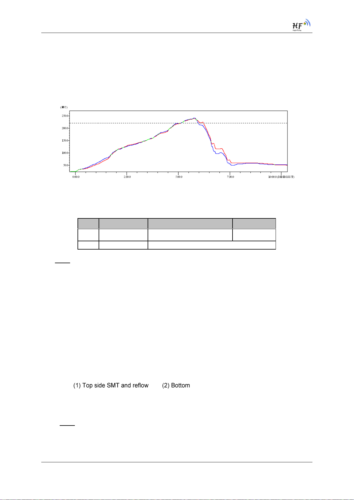
Figure 4. Reflow Soldering Profile
Table 11 Reflow Soldering Parameter
Note: 1. Recommend to supply N2 for reflow oven.
2. N2 atmosphere during reflow (O2<300ppm)
2.2. Device Handling Instruction (Module IC SMT Preparation)
1. Shelf life in sealed bag: 12 months, at <30℃and <60% relative humidity (RH)
2. After bag is opened, devices that will be re-baked required after last baked with window time
168 hours.
3. Recommend to oven bake with N2 supplied
4. Recommend end to reflow oven with N2 supplied
5. Baked required with 24 hours at 125+-5℃before rework process for two modules, one is
new module and two is board with module
6. Recommend to store at ≦10% RH with vacuum packing
7. If SMT process needs twice reflow:
side SMT and reflow
Case 1: Wifi module mounted on top side. Need to bake when bottom side process over 168
hours window time, no need to bake within 168 hours
Case 2: Wifi module mounted on bottom side, follow normal bake rule before process
Note: Window time means from last bake end to next reflow start that has 168 hours space.
NO.
Item
Temperature (Degree)
Time(Sec)
1
Reflow Time
Time of above 220
35~55 sec
2
Peak-Temp
260 max

HF-LPT120G Low Power Wi-Fi Module User Manual
Shanghai High-Flying Electronics Technology Co., Ltd(www.hi-flying.com) - 13 -
APPENDIX E: CONTACT INFORMATION
------------------------------------------------------------------------------------------------------------
Address: Room 1002,Building 1,No.3000,Longdong Avenue,Pudong New
Area,Shanghai,China,201203
Web: www.hi-flying.com
Service Online: 400-189-3108/18616078755
Sales Contact: sales@hi-flying.com
-----------------------------------------------------------------------------------------------------------
For more information about High-Flying modules, applications, and solutions, please visit our web site
http://www.hi-flying.com/en/
<END OF DOCUMENT>
© Copyright High-Flying, May, 2011
The information disclosed herein is proprietary to High-Flying and is not to be used by or disclosed to
unauthorized persons without the written consent of High-Flying. The recipient of this document shall respect the
security status of the information.
The master of this document is stored on an electronic database and is “write-protected” and may be altered only
by authorized persons at High-Flying. Viewing of the master document electronically on electronic database
ensures access to the current issue. Any other copies must be regarded as uncontrolled copies.
Table of contents
Other High-Flying Control Unit manuals


Popular Control Unit manuals by other brands


Viking
Viking SA--25 Technical practice

Genius
Genius JA592 Use and Installation Instructions

PPM
PPM ViaLiteHD HR-C-HB-3 Series user guide

Vestamatic
Vestamatic MC BS4 Installation and operating instructions

DataComm
DataComm 70-0023 Instruction/installation sheet

IFM Electronic
IFM Electronic DN0301 instruction manual

Tactical Power Products
Tactical Power Products PDM5 Series installation manual

Hirschmann
Hirschmann PTN-2-C37.94 user manual

Sun Microsystems
Sun Microsystems Sun Blade X6440 s installation guide

Vac - Alert
Vac - Alert Electro-Mechanical SVRS installation instructions

Commander
Commander SA-5000 manual

Fermator
Fermator ECC 230 V Assembly manual