HIMA HIMax X-DI 64 51 User manual

d
X-DI 64 51
HIMax®
Digital Input Module
Manual

HI 801 177 E 4.00 (1117)
All HIMA products mentioned in this manual are protected by the HIMA trade-mark. Unless noted
otherwise, this also applies to other manufacturers and their respective products referred to herein.
All of the instructions and technical specifications in this manual have been written with great care and
effective quality assurance measures have been implemented to ensure their validity. For questions,
please contact HIMA directly. HIMA appreciates any suggestion on which information should be
included in the manual.
Equipment subject to change without notice. HIMA also reserves the right to modify the written material
without prior notice.
For further information, refer to the CD-ROM and our website http://www.hima.de and
http://www.hima.com.
© Copyright 2011, HIMA Paul Hildebrandt GmbH + Co KG
All rights reserved
Contact
HIMA contact details:
HIMA Paul Hildebrandt GmbH + Co KG
P.O. Box 1261
68777 Brühl, Germany
Phone: +49 6202 709-0
Fax: +49 6202 709-107
Type of Change
Revision
index
Revisions
technical editorial
4.00 First Edition of the Manual

X-DI 64 51 Table of Contents
HI 801 177 E 4.00 Page 3 of 50
Table of Contents
1Introduction ............................................................ 5
1.1 Structure and Use of this Manual......................................................................... 5
1.2 Target Audience..................................................................................................... 5
1.3 Formatting Conventions ....................................................................................... 6
1.3.1 Safety Notes ............................................................................................................ 6
1.3.2 Operating Tips ......................................................................................................... 7
2Safety...................................................................... 8
2.1 Intended Use .......................................................................................................... 8
2.1.1 Environmental Requirements................................................................................... 8
2.1.2 ESD Protective Measures........................................................................................ 8
2.2 Residual Risk ......................................................................................................... 9
2.3 Safety Precautions................................................................................................. 9
2.4 Emergency Information......................................................................................... 9
3Product Description .............................................. 10
3.1 Safety Function.................................................................................................... 10
3.1.1 Reaction in the Event of a Fault............................................................................. 10
3.2 Scope of Delivery................................................................................................. 10
3.3 Type Label ............................................................................................................ 11
3.4 Structure............................................................................................................... 12
3.4.1 Block Diagram........................................................................................................ 12
3.4.2 Indicators ............................................................................................................... 13
3.4.3 Module Status Indicators ....................................................................................... 14
3.4.4 System Bus Indicators ........................................................................................... 15
3.4.5 I/O Indicators.......................................................................................................... 15
3.5 Product Data......................................................................................................... 16
3.6 Connector Boards................................................................................................ 18
3.6.1 Mechanical Coding of Connector Boards .............................................................. 18
3.6.2 Coding of X-CB 006 5X Connector Boards............................................................ 19
3.6.3 Connector Boards with Screw Terminals............................................................... 20
3.6.4 Terminal Assignment for Connector Boards with Screw Terminals....................... 21
3.6.5 Connector Boards with Cable Plug ........................................................................ 23
3.6.6 Pin Assignment for Connector Boards with Cable Plug......................................... 24
3.7 System Cable ....................................................................................................... 25
3.7.1 Cable Plug Coding ................................................................................................. 26

Table of Contents X-DI 64 51
Page 4 of 50 HI 801 177 E 4.00
4Start-up................................................................. 27
4.1 Mounting ...............................................................................................................27
4.1.1 Wiring Inputs Not in Use......................................................................................... 27
4.2 Mounting and Removing the Module..................................................................28
4.2.1 Mounting a Connector Board .................................................................................28
4.2.2 Mounting and Removing the Module...................................................................... 30
4.3 Configuring the Module in SILworX....................................................................32
4.3.1 Tab: Module ........................................................................................................... 33
4.3.2 Tab: I/O Submodule DI64_51................................................................................. 34
4.3.3 Tab: I/O Submodule DI64_51: Channels................................................................ 35
4.3.4 Submodule Status [DWORD] ................................................................................. 36
4.3.5 Diagnostic Status [DWORD]................................................................................... 37
4.4 Connection Variants.............................................................................................38
4.4.1 Input Wiring ............................................................................................................38
4.4.2 Wiring Transmitters via Field Termination Assembly ............................................. 40
5Operation .............................................................. 41
5.1 Handling................................................................................................................41
5.2 Diagnosis ..............................................................................................................41
6Maintenance.......................................................... 42
6.1 Maintenance Measures........................................................................................42
6.1.1 Loading the Operating System............................................................................... 42
6.1.2 Proof Test...............................................................................................................42
7Decommissioning.................................................. 43
8Transport .............................................................. 44
9Disposal................................................................ 45
Appendix............................................................... 46
Glossary................................................................................................................46
Index of Figures....................................................................................................47
Index of Tables .....................................................................................................48
Index......................................................................................................................49

X-DI 64 51 1 Introduction
HI 801 177 E 4.00 Page 5 of 50
1 Introduction
The present manual describes the technical characteristics of the module and its use. It
provides information on how to install, start up and configure the module in SILworX.
1.1 Structure and Use of this Manual
The content of this manual is part of the hardware description of the HIMax programmable
electronic system.
This manual is organized in the following main chapters:
Introduction
Safety
Product Description
Start-up
Operation
Maintenance
Decommissioning
Transport
Disposal
Additionally, the following documents must be taken into account:
Name Content Document no.
HIMax
System manual
Hardware description of the
HIMax system
HI 801 001 E
HIMax
Safety manual
Safety functions of the HIMax
system
HI 801 003 E
HIMax
Communication manual
Description of communication
and protocols
HI 801 101 E
SILworX Online Help
(OLH)
Instructions on how to use
SILworX
-
First Steps Introduction to SILworX HI 801 103 E
Table 1: Additional Relevant Manuals
The latest manuals can be downloaded from the HIMA website at www.hima.com. The
revision index on the footer can be used to compare the current version of existing manuals
with the Internet edition.
1.2 Target Audience
This document addresses system planners, configuration engineers, programmers of
automation devices and personnel authorized to implement, operate and maintain the
devices and systems. Specialized knowledge of safety-related automation systems is
required.

1 Introduction X-DI 64 51
Page 6 of 50 HI 801 177 E 4.00
1.3 Formatting Conventions
To ensure improved readability and comprehensibility, the following fonts are used in this
document:
Bold: To highlight important parts
Names of buttons, menu functions and tabs that can be clicked and
used in SILworX.
Italics: System parameter and variables
Courier Literal user inputs
RUN Operating state are designated by capitals
Chapter 1.2.3 Cross references are hyperlinks even though they are not
particularly marked. When the cursor hovers over a hyperlink, it
changes its shape. Click the hyperlink to jump to the corresponding
position.
Safety notes and operating tips are particularly marked.
1.3.1 Safety Notes
The safety notes are represented as described below.
These notes must absolutely be observed to reduce the risk to a minimum. The content is
structured as follows:
Signal word: danger, warning, caution, notice
Type and source of danger
Consequences arising from the danger
Danger prevention
The signal words have the following meanings:
Danger indicates hazardous situation which, if not avoided, will result in death or serious
injury.
Warning indicates hazardous situation which, if not avoided, could result in death or
serious injury.
Warning indicates hazardous situation which, if not avoided, could result in minor or
modest injury.
Notice indicates a hazardous situation which, if not avoided, could result in property
damage.
NOTICE
Type and source of damage!
Damage prevention
SIGNAL WORD
Type and source of danger!
Consequences arising from the danger
Danger prevention

X-DI 64 51 1 Introduction
HI 801 177 E 4.00 Page 7 of 50
1.3.2 Operating Tips
Additional information is structured as presented in the following example:
i
The text corresponding to the additional information is located here.
Useful tips and tricks appear as follows:
TIP The tip text is located here.

2 Safety X-DI 64 51
Page 8 of 50 HI 801 177 E 4.00
2 Safety
All safety information, notes and instructions specified in this manual must be strictly
observed. The product may only be used if all guidelines and safety instructions are
adhered to.
This product is operated in accordance with SELV or PELV. No imminent danger results
from the module itself. The use in Ex-Zone is permitted if additional measures are taken.
2.1 Intended Use
HIMax components are designed for assembling safety-related controller systems.
When using the components in the HIMax system, comply with the following general
requirements
2.1.1 Environmental Requirements
Requirement type Range of values
Protection class Protection class III in accordance with IEC/EN 61131-2
Ambient temperature 0...+60 °C
Storage temperature -40...+85 °C
Pollution Pollution degree II in accordance with IEC/EN 61131-2
Altitude < 2000 m
Housing Standard: IP20
Supply voltage 24 VDC
Table 2: Environmental Requirements
Exposing the HIMax system to environmental conditions other than those specified in this
manual can cause the HIMax system to malfunction.
2.1.2 ESD Protective Measures
Only personnel with knowledge of ESD protective measures may modify or extend the
system or replace modules.
NOTE
Device damage due to electrostatic discharge!
When performing the work, make sure that the working area is free of static and
wear an ESD wrist strap.
If not used, ensure that the device is protected from electrostatic discharge, e.g.,
by storing it in its packaging.

X-DI 64 51 2 Safety
HI 801 177 E 4.00 Page 9 of 50
2.2 Residual Risk
No imminent danger results from a HIMax module itself.
Residual risk may result from:
Faults in the engineering
Faults in the user program
Faults in the wiring
2.3 Safety Precautions
Observe all local safety requirements and use the protective equipment required on site.
2.4 Emergency Information
A HIMax controller is a part of the safety equipment of a system. If the controller fails, the
system adopts the safe state.
In case of emergency, no action that may prevent the HIMax systems from operating safely
is permitted.

3 Product Description X-DI 64 51
Page 10 of 50 HI 801 177 E 4.00
3 Product Description
The X-DI 64 51 standard module is a digital input module and it is intended for use in the
programmable electronic system (PES) HIMax.
The module can be inserted in any of the base plate slots with the exception of the slots
reserved for system bus modules. For more information, refer to the System Manual
(HI 801 001 E).
The module is used to evaluate up to 64 digital input signals. The digital inputs are current
sinking logic for 24 VDC signals in accordance with type 3 specified in the IEC 61131-2.
The standard module can be operated with safety-related modules within one base plate.
The standard module is non-reactive to the safety-related modules. In particular, this
includes EMC, electrical safety, communication to the X-SB and X-CPU modules and the
user program.
Module and connector boards are mechanically coded, see Chapter 3.6.1. This measure
ensures that a safety-related module cannot be replaced by a standard module.
Refer to the HIMax Safety Manual (HI 801 003 E) for more information on the standards
used to test and certify the modules and the HIMax system.
3.1 Safety Function
The module evaluates the digital input signals and provides them to the user program.
The module does not perform any safety-related functions.
The parameters and status for this module must not be used for safety functions.
3.1.1 Reaction in the Event of a Fault
If a fault occurs, the assigned input variables transmit the initial value (default value = 0) to
the user program.
The initial values must be set to 0 to ensure that the input variables transmit the value 0 to
the user program if a fault occurs.
The module activates the Error LED on the front plate.
3.2 Scope of Delivery
The module must be installed on a suitable connector board to be able to operate. If a FTA
is used, a system cable is required to connect the connector board to the FTA. Connector
boards, system cables and FTAs are not included within the scope of delivery.
The connector boards are described in Chapter 3.6, the system cables are described in
Chapter 3.7. The FTAs are described in own manuals.

X-DI 64 51 3 Product Description
HI 801 177 E 4.00 Page 11 of 50
3.3 Type Label
The type label specifies the following important details:
Product name
Mark of conformity
Bar code (2D or 1D code)
Part number (Part-No.)
Hardware revision index (HW Rev.)
Software revision index (SW Rev.)
Operating voltage (Power)
Ex specifications (if applicable)
Production year (Prod-Year:)
Figure 1: Sample Type Label
3 Product Description X-DI 64 51
Page 12 of 50 HI 801 177 E 4.00
3.4 Structure
The module has 64 digital inputs (24 V) for digital signals, contact makers and proximity
switches (two-wire). For safely detecting a high level on the digital input, the voltage and
current thresholds must be exceeded (see Table 8).
The eight short-circuit-proof supplies feed eight supply outputs each (S1+ to S8+). One
supply output is assigned to each digital input.
The processor system for the I/O module controls and monitors the I/O level. The data and
states of the I/O module are made available to the processor modules via the redundant
system bus. The system bus has a redundant structure for reasons of availability.
Redundancy is only ensured if both system bus modules are inserted in the base plates
and configured in SILworX.
The module is equipped with LEDs to indicate the status of the digital inputs, see
Chapter 3.4.2.
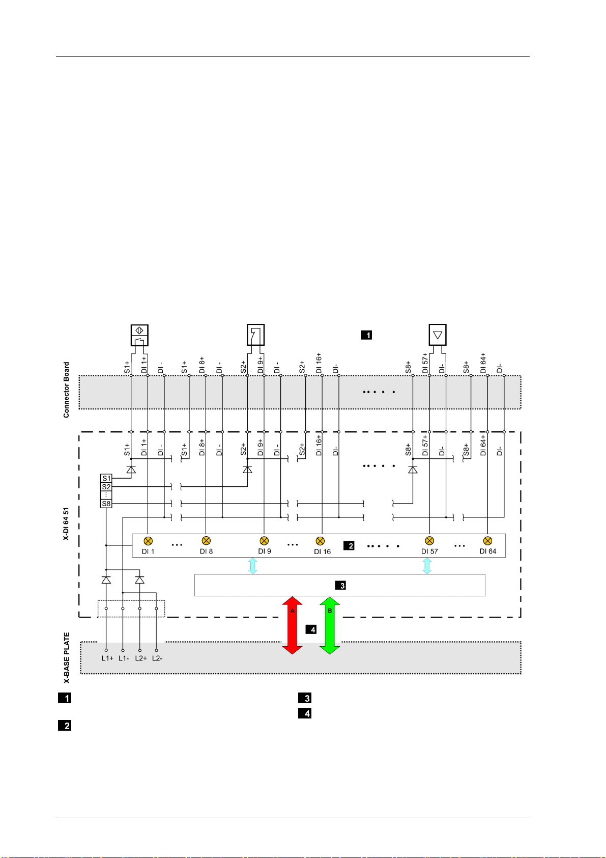
3.4.1 Block Diagram
The following block diagram illustrates the structure of the module.
Field Zone: Proximity Switches and Contact
Makers
Interface
Processsor System
System Busses
Figure 2: Block Diagram

X-DI 64 51 3 Product Description
HI 801 177 E 4.00 Page 13 of 50
3.4.2 Indicators
The following figure shows the LED indicators for the module.
Figure 3: Indicators

3 Product Description X-DI 64 51
Page 14 of 50 HI 801 177 E 4.00
The LEDs indicate the operating state of the module.
The LEDs on the module are divided into three groups:
Module status indicators (Run, Error, Stop, Init)
System bus indicators (A, B)
I/O indicators (DO 1...64, Field)
When the supply voltage is switched on, a LED test is performed and all LEDs briefly flash
simultaneously.
Definition of Blinking Frequencies
The following table defines the blinking frequencies of the LEDs:
Name Blinking Frequencies
Blinking1 Long (approx. 600 ms) on, long (approx. 600 ms) off
Blinking2 Short (approx. 200 ms) on, short (approx. 200 ms) off, short (approx. 200
ms) on, long (approx. 600 ms) off
Blinking-x Ethernet communication: Flashing in sync with data transfer
Table 3: Blinking Frequencies of LEDs
3.4.3 Module Status Indicators
These LEDs are located on the front plate, on the upper part of the module.
LED Color Status Description
On Module in RUN, normal operation
Blinking1 Module state:
STOP/OS_DOWNLOAD or
OPERATE (only with processor modules)
Run Green
Off Module not in RUN,
observe the other status LEDs
On/Blinking1 Internal module faults detected by self-tests, e.g.,
hardware, software or voltage supply.
Fault while loading the operating system
Error Red
Off Normal operation
On Module state:
STOP / VALID CONFIGURATION
Blinking1 Module state:
STOP / INVALID CONFIGURATION or
STOP / OS_DOWNLOAD
Stop Yellow
Off Module not in STOP, observe the other status LEDs
On Module state: INIT, observe the other status LEDs
Blinking1 Module state: LOCKED, observe to the other status
LEDs
Init Yellow
Off Module state: neither INIT nor LOCKED, observe
the other status LEDs
Table 4: Module Status Indicators

X-DI 64 51 3 Product Description
HI 801 177 E 4.00 Page 15 of 50
3.4.4 System Bus Indicators
The system bus LEDs are labeled Sys Bus.
LED Color Status Description
On Physical and logical connection to the system bus
module in slot 1.
Green
Blinking1 No physical connection to the system bus module in
slot 1.
A
Yellow Blinking1
The physical connection to the system bus module
in slot 1 has been established.
No connection to a (redundant) processor module
running in system operation.
On Physical and logical connection to the system bus
module in slot 2.
Green
Blinking1 No physical connection to the system bus module in
slot 2.
B
Yellow Blinking1
The physical connection to the system bus module
in slot 2 has been established.
No connection to a (redundant) processor module
running in system operation.
A+B Off Off Neither physical nor logical connection to the
system bus modules in slot 1 and slot 2.
Table 5: System Bus Indicators
3.4.5 I/O Indicators
The LEDs of the I/O indicators are labeled Channel.
LED Color Status Description
On The related channel is active (energized).
Blinking2 Channel fault
Channel
1…64
Yellow
Off The related channel is inactive (de-energized).
Blinking2 Field fault on at least one channel or supply (e.g.,
overcurrent, etc.)
Field Red
Off No field fault displayed!
Table 6: I/O Indicators LEDs

3 Product Description X-DI 64 51
Page 16 of 50 HI 801 177 E 4.00
3.5 Product Data
General
Supply voltage 24 VDC, -15 %...+20 %, rP≤5 %, SELV, PELV
Current input min. 400 mA
max. 800 mA
Current input per channel max. 4 mA
Operating temperature 0 °C...+60 °C
Storage temperature -40 °C...+85 °C
Humidity max. 95 % relative humidity, non-condensing
Type of protection IP20
Dimensions (H x W x D) in mm 310 x 29.2 x 230
Weight approx. 1.1 kg
Table 7: Product Data
Figure 4: Views

X-DI 64 51 3 Product Description
HI 801 177 E 4.00 Page 17 of 50
Digital inputs
Number of inputs (number of channels) 64 unipolar with reference pole DI- / L-,
Non-galvanically isolated from one another
Type of input Current sinking logic, 24 V, type 3 in
accordance with IEC 61131-2
Rated input voltage 0...24 V
Input voltage operating range -3...30 V, current limiting
2.3...2.9 mA (depending on the temperature)
Switching point typ. 9.4 V ± 0.8 V (2.1 mA ± 0.3 mA)
Refresh of measured values
(in the user program)
Cycle time of the user program
Table 8: Specifications for Digital Inputs
Supply
Number of sources 8 with 8 outputs each
Output voltage for supply Supply voltage - 2.5 V
Output current for supply 120 mA for each group
Short-circuit-proof
Assignment of the supply outputs
For supplying, the supply output assigned to the input must be used!
Supply S1+ DI1+…DI8+
Supply S2+ DI9+…DI16+
Supply S3+ DI17+…DI24+
Supply S4+ DI25+…DI32+
Supply S5+ DI33+…DI40+
Supply S6+ DI41+…DI48+
Supply S7+ DI49+…DI56+
Supply S8+ DI57+…DI64+
Table 9: Product Data for Supply

3 Product Description X-DI 64 51
Page 18 of 50 HI 801 177 E 4.00
3.6 Connector Boards
A connector board connects the module to the field zone. Module and connector board
form together a functional unit. Insert the connector board into the appropriate slot prior to
mounting the module.
The following connector boards are available for the module:
Connector board Description
X-CB 006 51 Connector board with screw terminals
X-CB 006 52 Redundant connector board with screw terminals
X-CB 006 53 Connector board with cable plug
X-CB 006 54 Redundant connector board with cable plug
Table 10: Available Connector Boards
3.6.1 Mechanical Coding of Connector Boards
I/O modules and connector boards are mechanically coded starting from hardware revision
AS00 to prevent them from being equipped with invalid I/O modules. Coding avoids
incorrect installation of invalid I/O modules thus preventing negative effects on redundant
modules and field zone. A part from that, invalid equipment has no effect on the HIMax
system since only I/O modules that are correctly configured in SILworX enter the RUN
state.
I/O modules and the corresponding connector boards have a mechanical coding in form of
wedges. The coding wedges in the female connector of the connector board match with the
male connector recesses of the I/O module plug, see Figure 5.
Coded I/O modules can only be plugged in to the corresponding connector boards.

X-DI 64 51 3 Product Description
HI 801 177 E 4.00 Page 19 of 50
Male Connector Recess
Prepared Male Connector Recess
Coding Wedge
Guideway for Coding Wedge
Figure 5: Coding Example
3.6.2 Coding of X-CB 006 5X Connector Boards
a7 a13 a20 a26 e7 e13 e20 e26
X X X
Table 11: Position of Coding Wedges

3 Product Description X-DI 64 51
Page 20 of 50 HI 801 177 E 4.00
3.6.3 Connector Boards with Screw Terminals
Mono Redundant
X-CB 006 51 X-CB 006 52
I/O Module Plug Connection to the Field Zone (Screw
Terminal Connector Block)
Figure 6: Connector Boards with Screw Terminals
Table of contents
Other HIMA Control Unit manuals

HIMA
HIMA HIMax X-MIO 7 01 User manual

HIMA
HIMA HIMax X-AI 32 02 User manual

HIMA
HIMA HIMax X-DI 32 05 User manual

HIMA
HIMA HIMax X-CI 24 51 User manual

HIMA
HIMA HIMax X-HART 32 01 User manual

HIMA
HIMA HIMax X-DI 64 01 User manual

HIMA
HIMA HIMatrix F60 Installation and operation manual

HIMA
HIMA HIMax X-COM 01 E User manual

HIMA
HIMA HIMax X-SB 01 User manual

HIMA
HIMA HIMatrix F60 DI 32 01 User manual


