Flo-Tite PRO-torQ ELO Series User manual


WARNING - Read and follow all instructions in this IOM manual and on the equipment. Failure
to follow instructions can cause severe injury and/or death.
WARNING – Risk of Electric Shock. All electrical wiring MUST be in conformance with
applicable local codes, regulations, and the National Electric Code (NEC). Hazardous voltage can
shock, burn, and cause death or serious property damage. To reduce the risk of electric shock, do
NOT use an extension cord to connect unit to electric supply. Provide a properly located electrical
receptacle. Before working on any electrical equipment, turn off power supply to the equipment.
WARNING – To reduce the risk of electric shock replace damaged wiring immediately.
WARNING – Ground all electrical equipment before connecting to electrical power supply.
Failure to ground all electrical equipment can cause serious or fatal electrical shock hazard.
WARNING – Do NOT ground to a gas supply line.
WARNING – To avoid dangerous or fatal electrical shock, turn OFF power to all electrical
equipment before working on electrical connections.
WARNING – Failure to bond all electrical equipment to system structure will increase risk for
electrocution and could result in injury or death. To reduce the risk of electric shock, see installation
instructions and consult a professional electrician on how to bond all electrical equipment. Also,
contact a licensed electrician for information on local electrical codes for bonding requirements.
CAUTION – Potential pinch point. Equipment connected to or driven by this device may start
unexpectedly and may cause personal injury or entrapment in linkage systems.
Basic safety precautions should always be followed, including the following: Failure to follow instructions
can cause severe injury and/or death.
This is the safety-alert symbol. When you see this symbol on your equipment or in this manual, look
for one of the following signal words and be alert to the potential for personal injury.
WARNING warns about hazards that could cause serious personal injury, death or major property
damage and if ignored presents a potential hazard.
CAUTION warns about hazards that will or can cause minor or moderate personal injury and/or
property damage and if ignored presents a potential hazard. It can also make consumers aware of
actions that are unpredictable and unsafe.
A notice indicates special instructions that are important but not related to hazards.
Notice:
IMPORTANT SAFETY INSTRUCTIONS
USE ONLY FLO-TITE GENUINE REPLACEMENT PARTS
ELo Rev C ECR 044V
Page 2 of 28
Back to TOC
www.flotite.com

ACTUATOR OPERATIONAL CONCEPTS
This document has active links which can be
used with mobile devices. Simply touch a line in
the Table of Contents to go directly to that page.
Other active links function the same way. The
Back to TOC link at the bottom of each page
returns to the TOC or Wiring Diagram index.
Important Safety Instructions ......................2
Table of Contents ................................3
Actuator Operational Concepts ..................3
Technical Information ............................4
Conventions Used in this Manual ................4
Actuator Handling And Installation ..................5
Shipping and Handling ........................5
Installation Notes .............................5
Product Mounting and Setup ......................6
Torque Switches ................................7
Adjusting CW End of Travel .......................8
Adjusting CCW End of Travel ......................9
Adjusting Auxiliary Switches ......................10
Cam Behavior ...............................10
Auxiliary Switch Cam Mapping ..................10
Calibration ....................................11
On/Off Only ................................11
Commissioning .................................11
On/Off Only ................................11
Proportional Calibration .........................12
(120-230VAC Models) ........................12
Calibration - Continued........................13
Proportional Calibration .........................14
(12-24VAC/DC Models) .......................14
Calibration - Continued........................15
Commissioning ................................16
Proportional Control .........................16
Troubleshooting ................................17
On/Off Models ..............................17
Troubleshooting ................................18
Proportional Models .........................18
Mechanical Data ...............................19
Dimensional Data ...........................19
Exploded View ..............................20
Wire Sizing Chart ...............................21
Wiring Diagrams ...............................22
Elo-N-AC 12VAC/VDC On/Off .................................. .22
Elo-N-AC 12VAC/VDC Proportional ......................... 23
Elo-N-B 24VAC/VDC On/Off D/F................................ 24
Elo-N-B 24VAC/VDC Proportional D/F...................... 25
Elo-N- 120/230VAC On/Off R/L.................................. 26
Elo-N- 120/230VAC Proportional R/L......................... 27
Pages 8-9 - Travel limits for CW (CLOSED) & CCW (OPEN) positions, HRSN3 Series
Page 10 - Auxiliary switch cams for CW & CCW positions, HRSN3 Series
Single phase actuators range in complexity from simple models with basic operability, to quite complicated
models with battery backup and local control capabilities. The various models might seem to be easily adaptable
across any site or design intent, but are actually very specic a s to h ow they i nterface t o e xisting o r n ew
installations. It is important to FULLY UNDERSTAND what level of control is required prior to selecting one of
these products. While it might make sense to opt for the most feature-laden solution in order to cover all the
possibilities in a given application, that selection in fact would NOT function in an application that just required
the most basic unit.
Notice: Read the project specications and understand the application before making an actuator selection. If
in doubt, consult with the project engineer to clarify what is actually required for a fully operational installation.
We have provided in this document all the tools necessary to determine how the various levels interface to
the outside world. If there are any questions, please contact Flo-Tite.
Notice: HRSN3 Series actuators are fully assembled, calibrated and tested prior to leaving our factory. In most cases, after
you have mounted the actuator to your device, you should be able to operate the actuator from fully CLOSED (CW) to fully
OPEN (CCW) and back again, and nd that no adjustments are needed. The assembly can be put into service immediately.
However, should it be necessary to make adjustments to the end-of-travel positions to overcome any device related issues
(i.e. valve shaft incorrectly timed to the drive stem), the procedures outlined below should be followed to put the assembly
into service. Note that there is a maximum adjustment range of +/- 3° at each end of travel.
TABLE OF CONTENTS
(/2 Series
USE ONLY FLO-TITE GENUINE REPLACEMENT PARTS
ELo Rev C ECR 044V
Page 3 of 28
Back to TOC
www.flotite.com

Supply Torque Output (lbf-in / Nm) 880 / 100 1770 / 200
12VAC
-
12VDC
Current Draw (Start / Run / LRA) 7.2A / 5.2A / 17.8A 7.2A / 5.2A / 17.8A
Speed (90°) DC, seconds 14 28
Motor - 12vdc Perm Magnet Brush Type 25W 25W
Duty Cycle (on/off / mod) 75% 75%
Motor Starts, per hour, Max 1200 1200
Motor Protection, Temp / Class 135°C / Class F 135°C / Class F
24VAC
-
24VDC
Current Draw (Start / Run / LRA) 4.2A / 3.2A / 11A 4.2A / 3.2A / 11A
Speed (90°) DC, seconds 14 28
Motor - 24vdc Perm Magnet Brush Type 25W 25W
Duty Cycle (on/off / mod) 75% 75%
Motor Starts, per hour, Max 1200 1200
Motor Protection, Temp / Class 135°C / Class F 135°C / Class F
120V
Current Draw (Start / Run / LRA) 1.16A / 0.93A / 1.47A 1.16A / 0.93A / 1.47A
Speed (90°) 60Hz / 50Hz, seconds 16 / 19 33 / 39
Motor - 120vac Split-Phase Cap TENV 40W 40W
Duty Cycle (on/off / mod) 25% / 75% 25% / 75%
Motor Starts, per hour, Max 1200 1200
Motor Protection, Temp / Class 135°C / Class F 135°C / Class F
230V
Current Draw (Start / Run / LRA) 0.54A / 0.42A / 0.66A 0.54A / 0.42A / 0.66A
Speed (90°) 60Hz / 50Hz, seconds 16 / 19 33 / 39
Motor - 230vac Split-Phase Cap TENV 40W 40W
Duty Cycle (on/off / mod) 25% / 75% 25% / 75%
Motor Starts, per hour, Max 1200 1200
Motor Protection, Temp / Class 135°C / Class F 135°C / Class F
All
Environmental Rating NEMA 4/4X/IP67
Electrical Entry (2) 3/4" EMT or ABS gland
Control On/Off or Proportional
Ambient Operating Range -22°F to +158°F / -30°C to +70°C
Humidity Range 0-95% RH
Altitude Limit 9850 ft / 3000 m
Below are Terms and Denitions used throughout this manual.
1. XTS/TS product manufactured without/with Torque Switches.
2. XFS/FS product manufactured without/with Fail Safe built-in.
3. LCS is an industry acronym for a Local Control Station.
CONVENTIONS USED IN THIS MANUAL
Use this table to efciently select the actuator and wiring diagram you require.
Control Voltage Torque Switches Fail Safe Local Control Station IOM Wiring Diagram Page
On/Off 12VDC/VAC XTS/TS XFS None This IOM 22
Proportional 12VDC/VAC XTS/TS XFS None This IOM 23
On/Off 24VDC/VAC XTS/TS XFS None This IOM 24
Proportional 24VDC/VAC XTS/TS XFS None This IOM 25
On/Off 120VAC XTS/TS XFS None This IOM 26
Proportional 120VAC XTS/TS XFS None This IOM 27
On/Off 230VAC XTS/TS XFS None This IOM 26
Proportional 230VAC XTS/TS XFS None This IOM 27
On/Off / Proportional 24VDC/VAC XTS/TS FS None HRSN3FSIOM
reference correct IOM
On/Off / Proportional 120-230VAC XTS/TS FS None HRSN3FSIOM
On/Off / Proportional* 24VDC/VAC XTS/TS XFS LCS HRCK3IOM
On/Off / Proportional 120-230VAC XTS/TS XFS LCS HRCK3IOM
ACTUATOR OPTIONS
ACTUATOR SPECIFICATIONS Elo-NA8 Elo-NB9
* No 24VDC/VAC can be equipped with HRCL/CD options
TECHNICAL INFORMATION
USE ONLY FLO-TITE GENUINE REPLACEMENT PARTS
ELo Rev C ECR 044V
Page 4 of 28
Back to TOC
www.flotite.com

1. Position on arrival:
•A separate actuator arrives in the FULLY CLOSED (CW) position. The
red/green position indicator (see illustration) shows RED.
•A 2 way ball valve assembly arrives in the FULLY OPEN (CCW) position
and the position indicator shows GREEN.
•A 2 way buttery valve assembly arrives nearly CLOSED (5°) position
and the position indicator shows mostly RED.
2. Storage: This unit should not be stored outside unless it is powered up and
has proper conduit terminations. When not powered up, it should be stored
in a clean, dry environment at all times.
3. This quarter-turn actuator has been factory tested and calibrated to operate
between 0° and 90°. Most products will not require recalibration of these
settings. If any travel adjustment is necessary, please refer to the Adjusting
CW/CCW End of Travel section for instructions.
4. Notice: The Series actuators have mechanical stops which limit
rotation. Do not attempt to operate with a rotation greater than 95°.
5. Notice: Protect the actuator from moisture by installing it with water tight
EMT ttings and proper conduit drainage. Supply power to the unit to keep
the internal heater warm at the time of installation.
SHIPPING AND HANDLING
INSTALLATION NOTES
The actuator has a red and green position
indicator. RED color in the indicator
window means the actuator is fully
CW, while GREEN means it is fully CCW.
The manual override handwheel
allows a user to position the valve or
damper with or without power. Turn
the handwheel CW to make the output
drive move CW (when viewed from
above). Turning the handwheel CCW
makes the output drive turn CCW.
WARNING – To avoid dangerous or fatal electrical shock,
turn OFF power to all electrical equipment
before working on electrical connections.
CAUTION – Please follow the following guidelines for proper installation.
•These actuators are designed to be used between a horizontal and
upright position. Do NOT mount the assembly with the actuator top
below a horizontal position (i.e. upside down).
•When installing conduit, use proper techniques for entry into the actuator.
Use drip loops to prevent conduit condensate from entering the actuator.
• Mechanical travel stops are factory calibrated for 90 degree operation.
These stops are NOT designed to adjust mechanical rotation by more
than +/- 3 degrees, they are for positioning the handwheel only.
• Both EMT conduit ports MUST use proper equipment to protect the
NEMA 4X integrity of the housing.
• The internal heater is to be used in ALL applications.
•Do NOT install the actuator outdoors or in humid environments unless it
is powered up and the heater is functioning.
• Use proper wire size to prevent actuator failure (see Wire Sizing Chart for
proper wire sizing).
• All terminals accept 12-18AWG solid/stranded wire.
•Notice: Do NOT parallel wire multiple on/off actuators together without
utilizing isolation relays. If this is your intention, please contact Flo-Tite for
a multiple actuator parallel wiring diagram.
HRSN3
* No 24VDC/VAC can be equipped with HRCL/CD options
ACTUATOR HANDLING AND INSTALLATION
USE ONLY FLO-TITE GENUINE REPLACEMENT PARTS
ELo Rev C ECR 044V
Page 5 of 28
Back to TOC
www.flotite.com

1. Fully CLOSE the valve or damper to which the actuator is to be mounted.
2. Assemble necessary linkage hardware and attach the actuator to the valve
or damper.
3. Center the actuator on the valve or damper drive shaft and tighten all hardware.
4. Before applying power to the unit, rotate the manual override handwheel
from the fully CW to the fully CCW position to check for unobstructed manual
operation of the valve or damper.
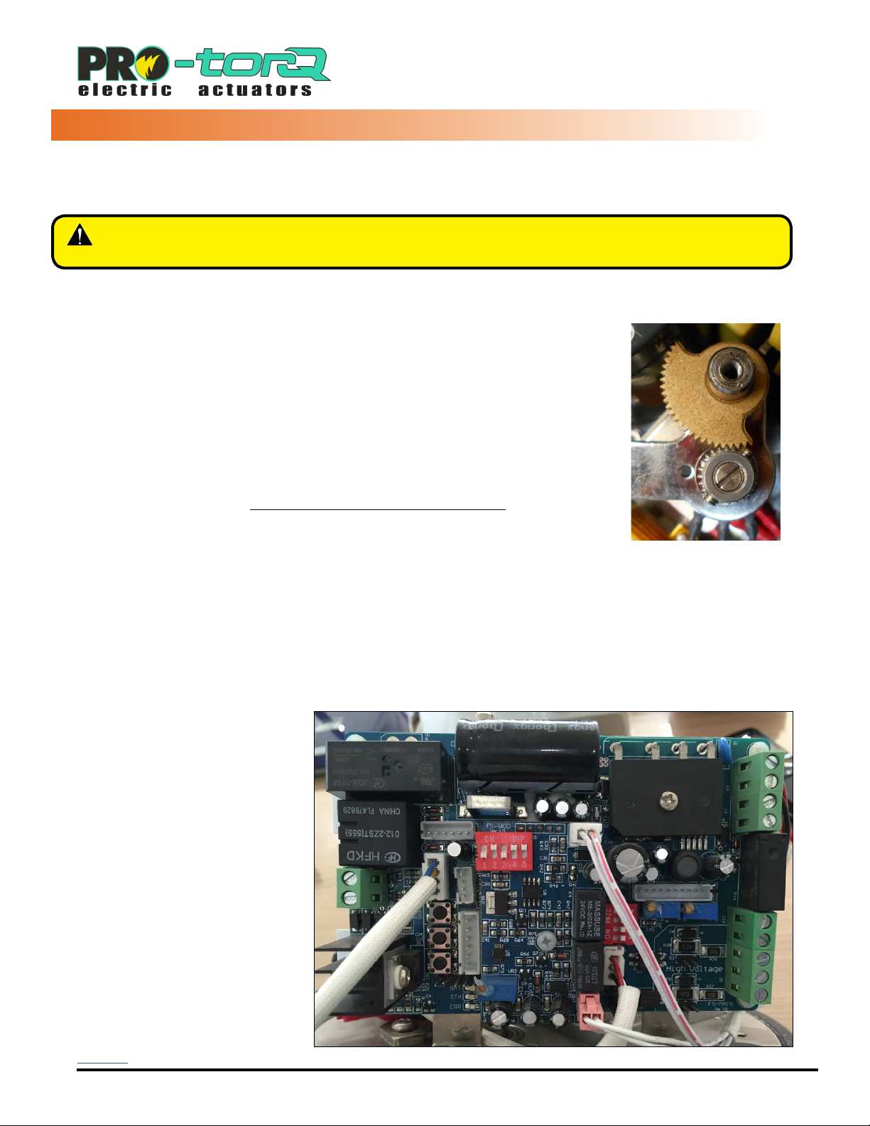
5. Series actuators utilize a removable terminal block to simplify eld
wiring and testing.
•To remove a terminal block from the PCB receiver, pull straight out in a
direction parallel to the PCB.
•In the photo at right, the RIGHT side of either terminal block (between the
PCB mounting screws) is pulled out to the RIGHT.
•After wiring, reinsert the terminal strip into the receiver.
This is a keyed pair and can only be inserted one way.
•Screw terminals are rated to accept 14AWG down to 18AWG solid or
stranded wire. TERMINAL NUMBERING HAS #1 AT THE BOTTOM.
6. Refer to your product part number to determine which wiring diagram to
follow when wiring up the actuator.
7. Note that although terminals are labeled as 1-8 and A-D, not all terminals are
used on all models.
Removable terminal blocks facilitate
ease of eld wiring and testing.To
remove a terminal block from the PCB
receiver,pull straight OUT in a direction
parallel to the PCB. Use caution
when reinserting block - make sure
all pins are aligned before seating.
Torque Switch (TS) equipped
products have a secondary set
of cams/switches to protect the
actuator, equipment and processes.
CCW
CW
Notethat therotation seenfrom below isa
mirrorof thedirectionviewed fromabove.
CAUTION – Be sure to make eld connections to the proper terminal
as identied by the LABEL and not the position!
Notice: Torque switches are factory set and are not adjustable.
8. Make the electrical connections per the appropriate Wiring Diagram for
your actuator.
9. Connect POWER and CONTROL to the correct terminals.
10. Terminals A~D on each actuator are for the (adjustable) auxiliary switches.
These are dry type (volt free) Form A contacts rated 250VAC @ 10A Max.
11. Select actuators covered in this manual are equipped with torque switches
which protect the actuator motor and gear train. Torque switches protect
controlled valves or actuators from damage in the event of a high torque
condition. More information can be found throughout this manual.
Notice: All HRSN3 Series actuators rotate CW to close the output shaft
out the bottom of the actuator when viewed from above. On all HRSN3
models, the cam shaft and the indicator rotate CW to close as well.
HRSN3
PRODUCT MOUNTING AND SETUP
USE ONLY FLO-TITE GENUINE REPLACEMENT PARTS
ELo Rev C ECR 044V
Page 6 of 28
Back to TOC
www.flotite.com

Torque Switch Operation
Select HRSN3 units have torque switches to protect the actuator and any attached equipment from possible damage
which can occur in a high torque event. In such an event the valve or damper being driven encounters some blockage
or impediment to travel. In the case of an actuator without torque switches, the actuator will attempt to drive until it
Torque Switch cams and switches are shown
in the normal operating position.
Upper torque switch and
cam for actuator drive CW
rotation
Lower torque switch and
cam for actuator drive
CCW rotation
Upper cam has rotated
counter clockwise from its
neutral position and has
engaged the switch.
Torque Switch cams shown with the
upper cam tripping the upper switch
(Actuator was driving CW before this trip)
WARNING – Torque switches are factory set and are NOT ADJUSTABLE.
Changing these settings will void the actuator warranty.
either reaches the end of travel or (likely) the motor
overworks and trips on a thermal overload. Units
with torque switches will cease supplying power
to the motor when a high torque event occurs.
Torque Switch (Normal Mode)
1. In normal operating mode, the torque switch
and drive cam are in the neutral position
shown in the photo.
2. Internal gearing in line with the output drive
provide the rotational action for the cams.
3. Upper torque switch protects CW rotation.
4. Lower torque switch protects CCW rotation.
Torque Event (CW)
1. The photo at left shows a high torque event in
the CW direction
2. The torque switch CW drive cam (upper) and
switch are in the tripped position.
3. When the torque switch trips, it immediately
cuts off power ow to the motor for that
direction of travel.
Torque Event (CCW)
1. The photo at left shows a high torque event in
the CCW direction
2. The torque switch CCW drive cam (lower) and
switch are in the tripped position.
3. When the torque switch trips, it immediately
cuts off power ow to the motor for that
direction of travel.
Lower cam has rotated
clockwise from its neutral
position (above) and has
engaged the switch.
TORQUE SWITCHES
Torque Switch cams shown with
the lower cam tripping the lower
switch (Actuator was driving CCW before
this trip)
USE ONLY FLO-TITE GENUINE REPLACEMENT PARTS
ELo Rev C ECR 044V
Page 7 of 28
Back to TOC
www.flotite.com

CAUTION! - The mechanical
stop screw limits handwheel
operation ONLY and is NOT to
be used as an electrical travel
limiting device.
This actuator has been factory calibrated and tested to stop at 0 degrees for CW position and to stop at 90 degrees
for CCW position. Most installations onto valves or dampers will likely not require recalibration of these settings. Please
mount the valve or damper and proceed on these pages only if adjustments are required. Note that for most actuators
these positions are independent - for instance the CW position is accurate while the CCW position might need adjustment.
WARNING – Serious Damage to the actuator will result if the motor is allowed to drive the gear train into the
mechanical stop! Remove power from this device BEFORE making any travel adjustments.
Reposition Mechanical Stop
1. Disconnect power.
2. Loosen the RIGHT SIDE mechanical stop. This is the CW mechanical stop
limit adjustment. Using a 17mm wrench and a 5mm hex key, hold the jam
nut and turn the stop screw 5-6 turns CCW so it clears the mechanical boss
inside the actuator.
•This will allow you to adjust the cam/switch stop position
without running into the mechanical stop screw.
3. Use the manual override handwheel to position the actuator to your required
CW position. Keep all changes within +/- 3 degrees of the factory setting.
Adjust CW Cam (Bottom)
4. Cam 1 is the bottom cam (red) and is the end-of-travel adjustment for the
actuator CW position. With POWER OFF and the actuator at its required
CW position, use a sharp 2.5mm hex key to free up the cam set screw.
Take care not to let the hex key slip at this stage, it can easily strip out.
Once it is free adjust it as described below:
•Rotate the hex key to the RIGHT 10-15
degrees until you hear a click. This will
reset the switch roller arm.
•Gently tighten (CW) the set screw only
until slight pressure is felt. Ideally the
set screw rides along the camshaft.
•Now SLOWLY rotate the hex key to the
LEFT, pushing the cam, until you hear
the “click” on the bottom switch. The
click means correct adjustment has
been achieved.
•Tighten the cam set screw.
5. Apply power and test for the correct CW position:
•Drive the actuator CCW at least 15-20 degrees.
•Drive the actuator CW until the cam stops the electrical travel.
•Check to be sure this is the correct CW position you require.
Repeat the steps of item 4 if further adjustment is needed.
Tighten Mechanical Stop
1. With the actuator in the proper position. Hold the 17mm wrench on the
RIGHT SIDE jam nut to prevent the jam nut from locking and turn the 5mm
hex key CW until the end of the stop screw bottoms out against the internal
stop boss.
2. Turn the hex key ONE FULL TURN CCW and lock this position with the jam
nut. Now the actuator will reach its end of travel electrically before there is
any interference from the mechanical stop.
3. CW position calibration is now complete.
CW Mechanical Stop
Cam 1 - CW Cam
CW Mechanical Stop
COM
NO NC
COM
NO NC
CW Limit Switch
Shown in CCW Position
CCW Limit Switch
Shown in CCW Position
Adjust for
Less CW
Adjust for
More CW
Adjust for
More CCW
Adjust for
Less CCW
COM
NO NC
Will drive 90°CW
CCW Limit Switch
Shown in Full CW Position
COM
NO NC
CW Limit Switch
Shown in Full CW Position
Will drive 90°CCW
CAUTION! - The mechanical
stop screw limits handwheel
operation ONLY and is NOT to
be used as an electrical travel
limiting device.
This actuator has been factory calibrated and tested to stop at 0 degrees for CW position and to stop at 90 degrees
for CCW position. Most installations onto valves or dampers will likely not require recalibration of these settings. Please
mount the valve or damper and proceed on these pages only if adjustments are required. Note that for most actuators
these positions are independent - for instance the CW position is accurate while the CCW position might need adjustment.
WARNING – Serious Damage to the actuator will result if the motor is allowed to drive the gear train into the
mechanical stop! Remove power from this device BEFORE making any travel adjustments.
COM
NO NC
COM
NO NC
CW Limit Switch
Shown in CCW Position
CCW Limit Switch
Shown in CCW Position
Adjust for
Less CW
Adjust for
More CW
Adjust for
More CCW
Adjust for
Less CCW
COM
NO NC
Will drive 90°CW
CCW Limit Switch
Shown in Full CW Position
COM
NO NC
CW Limit Switch
Shown in Full CW Position
Will drive 90°CCW
CCW Mechanical Stop
Cam 2 - CCW Cam
CCW Mechanical Stop
Reposition Mechanical Stop
1. Disconnect power.
2. Loosen the LEFT SIDE mechanical stop. This is the CCW mechanical stop
limit adjustment. Using a 17mm wrench and a 5mm hex key, hold the jam
nut and turn the stop screw 5-6 turns CCW so it clears the mechanical boss
inside the actuator.
•This will allow you to adjust the cam/switch stop position
without running into the mechanical stop screw.
3. Use the manual override handwheel to position the actuator to your required
CCW position. Keep all changes within +/- 3 degrees of the factory setting.
Adjust CCW Cam (Second from Bottom)
4. Cam 2 is the second cam up from the bottom (green) and is the end-of-
travel adjustment for the actuator CCW position. With POWER OFF and the
actuator at its required CCW position, use a sharp 2.5mm hex key to free
up the cam set screw. Take care not to let the hex key slip at this stage,
it can easily strip out. Once it is free adjust it as described below:
•Rotate the hex key to the LEFT 10-15
degrees until you hear a click. This will
reset the switch roller arm.
•Gently tighten (CW) the set screw only
until slight pressure is felt. Ideally the
set screw rides along the camshaft.
•Now SLOWLY rotate the hex key to the
RIGHT, pushing the cam, until you hear
the “click” on the bottom switch. The
click means correct adjustment has
been achieved.
•Tighten the cam set screw.
5. Apply power and test for the correct CCW position:
•Drive the actuator CW at least 15-20 degrees.
•Drive the actuator CCW until the cam stops the electrical travel.
•Check to be sure this is the correct CCW position you require.
Repeat the steps of item 4 if further adjustment is needed.
Tighten Mechanical Stop
1. With the actuator in the proper position, hold the 17mm wrench on the
LEFT SIDE jam nut to prevent the jam nut from locking and turn the 5mm
hex key CW until the end of the stop screw bottoms out against the internal
stop boss.
2. Turn the hex key ONE FULL TURN CCW and lock this position with the jam
nut. Now the actuator will reach its end of travel electrically before there is
any interference from the mechanical stop.
3. CCW position calibration is now complete.
ADJUSTING CW END OF TRAVEL
USE ONLY FLO-TITE GENUINE REPLACEMENT PARTS
ELo Rev C ECR 044V
Page 8 of 28
Back to TOC
www.flotite.com

CAUTION! - The mechanical
stop screw limits handwheel
operation ONLY and is NOT to
be used as an electrical travel
limiting device.
This actuator has been factory calibrated and tested to stop at 0 degrees for CW position and to stop at 90 degrees
for CCW position. Most installations onto valves or dampers will likely not require recalibration of these settings. Please
mount the valve or damper and proceed on these pages only if adjustments are required. Note that for most actuators
these positions are independent - for instance the CW position is accurate while the CCW position might need adjustment.
WARNING – Serious Damage to the actuator will result if the motor is allowed to drive the gear train into the
mechanical stop! Remove power from this device BEFORE making any travel adjustments.
COM
NO NC
COM
NO NC
CW Limit Switch
Shown in CCW Position
CCW Limit Switch
Shown in CCW Position
Adjust for
Less CW
Adjust for
More CW
Adjust for
More CCW
Adjust for
Less CCW
COM
NO NC
Will drive 90°CW
CCW Limit Switch
Shown in Full CW Position
COM
NO NC
CW Limit Switch
Shown in Full CW Position
Will drive 90°CCW
CCW Mechanical Stop
Cam 2 - CCW Cam
CCW Mechanical Stop
Reposition Mechanical Stop
1. Disconnect power.
2. Loosen the LEFT SIDE mechanical stop. This is the CCW mechanical stop
limit adjustment. Using a 17mm wrench and a 5mm hex key, hold the jam
nut and turn the stop screw 5-6 turns CCW so it clears the mechanical boss
inside the actuator.
•This will allow you to adjust the cam/switch stop position
without running into the mechanical stop screw.
3. Use the manual override handwheel to position the actuator to your required
CCW position. Keep all changes within +/- 3 degrees of the factory setting.
Adjust CCW Cam (Second from Bottom)
4. Cam 2 is the second cam up from the bottom (green) and is the end-of-
travel adjustment for the actuator CCW position. With POWER OFF and the
actuator at its required CCW position, use a sharp 2.5mm hex key to free
up the cam set screw. Take care not to let the hex key slip at this stage,
it can easily strip out. Once it is free adjust it as described below:
•Rotate the hex key to the LEFT 10-15
degrees until you hear a click. This will
reset the switch roller arm.
•Gently tighten (CW) the set screw only
until slight pressure is felt. Ideally the
set screw rides along the camshaft.
•Now SLOWLY rotate the hex key to the
RIGHT, pushing the cam, until you hear
the “click” on the bottom switch. The
click means correct adjustment has
been achieved.
•Tighten the cam set screw.
5. Apply power and test for the correct CCW position:
•Drive the actuator CW at least 15-20 degrees.
•Drive the actuator CCW until the cam stops the electrical travel.
•Check to be sure this is the correct CCW position you require.
Repeat the steps of item 4 if further adjustment is needed.
Tighten Mechanical Stop
1. With the actuator in the proper position, hold the 17mm wrench on the
LEFT SIDE jam nut to prevent the jam nut from locking and turn the 5mm
hex key CW until the end of the stop screw bottoms out against the internal
stop boss.
2. Turn the hex key ONE FULL TURN CCW and lock this position with the jam
nut. Now the actuator will reach its end of travel electrically before there is
any interference from the mechanical stop.
3. CCW position calibration is now complete.
ADJUSTING CCW END OF TRAVEL
USE ONLY FLO-TITE GENUINE REPLACEMENT PARTS
ELo Rev C ECR 044V
Page 9 of 28
Back to TOC
www.flotite.com

This actuator has been factory calibrated and tested to stop at 0 degrees for CW position and to stop at 90 degrees
for CCW position. The Auxiliary Switch settings are based on those stops. Ideally the Auxiliary Switches are set a few
degrees in advance of the respective stop switches, so if you had adjusted either the CW or CCW you may need to
adjust these as well.
COM
NO NC
COM
NO NC
CW Limit Switch
Shown in CCW Position
CCW Limit Switch
Shown in CCW Position
Adjust for
Less CW
Adjust for
More CW
Adjust for
More CCW
Adjust for
Less CCW
COM
NO NC
Will drive 90°CW
CCW Limit Switch
Shown in Full CW Position
COM
NO NC
CW Limit Switch
Shown in Full CW Position
Will drive 90°CCW
COM
NO NC
COM
NO NC
CW Limit Switch
Shown in CCW Position
CCW Limit Switch
Shown in CCW Position
Adjust for
Less CW
Adjust for
More CW
Adjust for
More CCW
Adjust for
Less CCW
COM
NO NC
Will drive 90°CW
CCW Limit Switch
Shown in Full CW Position
COM
NO NC
CW Limit Switch
Shown in Full CW Position
Will drive 90°CCW
Cam 3 - CW Auxiliary Cam
Cam 4 - CCW Auxiliary Cam
Adjust CW Auxiliary Cam
1. Cam 3 is the third cam up from the bottom (red) and is the CW auxiliary
switch adjustment, an optional switch typically used to indicate the actuator
reached its CW position.
2. Drive the actuator to its CW position. Use a sharp 2.5mm hex key to free up
the cam set screw. Take care not to let the hex key slip at this stage, it
can easily strip out. Once it is free adjust it as described below:
•Rotate the hex key to the RIGHT 10-15 degrees until you hear
a click. This will reset the switch roller arm.
•Gently tighten (CW) the set screw only until slight pressure is
felt. Ideally the set screw rides along the camshaft.
•Now SLOWLY rotate the hex key to the LEFT, pushing the cam,
until you hear the “click” on the bottom switch.
•Continue to rotate the cam between 3 and 5 degrees to the
LEFT to make sure the auxiliary cam switch changes state
before the actuator reaches its end of travel electrically.
•Tighten the cam set screw.
Adjust CCW Auxiliary Cam
1. Cam 4 is the fourth cam up from the bottom (green) and is the CCW
auxiliary switch adjustment, an optional switch typically used to indicate
the actuator reached its CCW position.
2. Drive the actuator to its CCW position. Use a sharp 2.5mm hex key to free
up the cam set screw. Take care not to let the hex key slip at this stage,
it can easily strip out. Once it is free adjust it as described below:
•Rotate the hex key to the LEFT 10-15 degrees until you hear a
click. This will reset the switch roller arm.
•Gently tighten (CW) the set screw only until slight pressure is
felt. Ideally the set screw rides along the camshaft.
•Now SLOWLY rotate the hex key to the RIGHT, pushing the
cam, until you hear the “click” on the bottom switch.
•Continue to rotate the cam between 3 and 5 degrees to the
RIGHT to make sure the auxiliary cam switch changes state
before the actuator reaches its end of travel electrically.
•Tighten the cam set screw.
D
C
B
A
SW3 CW AUX
(Adjustable)
SW4 CW AUX
(Adjustable) CAM 4
CAM 3
CAM 2
CAM 1
}
}
}
Common Switch Terminal
Common
Fully CCW (OPEN)
Common
Fully CW (CLOSED)
SW1 and SW2
Used by Controller
-5°0°
CW CCW
85°
5°90°95°
Red lines show when the contact is energized.
ADJUSTING AUXILIARY SWITCHES
CAM BEHAVIOR
AUXILIARY SWITCH CAM MAPPING
USE ONLY FLO-TITE GENUINE REPLACEMENT PARTS
ELo Rev C ECR 044V
Page 10 of 28
Back to TOC
www.flotite.com

The end stop travel (cams) of this actuator have been factory set and tested to respond between 0° and 90°
degrees rotation. If NO changes to end stops are required, this unit is ready to be put into service immediately
using this procedure. IF changes to the cam positions are required, refer to pages 8 ~ 10 before proceeding.
WARNING – Serious Damage to the actuator will result if the motor is allowed to drive the gear train
into the mechanical stop! Remove power from this device BEFORE making any travel adjustments.
WARNING – Follow these directions carefully and in order. Actuator damage due to improper testing
and commissioning will NOT be covered under warranty.
Calibration Procedure - On/Off Control
1. Apply correct power according to the actuator model, referring to wiring diagrams.
2. Position the actuator to its full CCW (Open) and/or CW (Closed) positions and adjust the cams as necessary.
3. After making cam adjustments on either or both ends of travel, it is advisable to move off cam slightly, and then
repeat the drive command to assure the cam settings are correct.
4. Be sure the cam setscrews are snug (overtightening during calibration will make it difcult to make minor
incremental adjustments).
5. Unit is now calibrated and is ready to be put into service. No other calibration is necessary.
Commissioning Procedure - On/Off Control
1. Utilize the handwheel or override shaft to rotate the actuator and damper, valve or other connected device through
its full travel from full CW to full CCW and back again to check for any possible interference. Do NOT utilize any
mechanical advantage devices to rotate the handwheel (pipes, wrenches, extension bars, etc.).
2. Manually position the actuator to its mid-stroke position.
3. Apply correct power to the unit.
4. Measure correct power and polarity on terminals 1 & 2 AT THE MAIN TERMINAL BLOCK.
5. Command the eld device to generate a CCW signal. The actuator rotates in a CCW direction (as viewed from above).
6. Measure terminals 2 and 6 (Run CCW) for correct voltage (matching that measured in step 4).
7. Actuator will stop when it reaches it’s full CCW position.
8. With eld command signal still present, measure terminals 2 and 5 and read voltage to match that measured in
step 4.
9. Read continuity between terminals C & D to show the CCW Aux switch is closed.
10. Command the eld device to generate a CW signal. The actuator rotates in a CW direction (as viewed from above).
11. Measure terminals 2 and 4 (Run CW) for correct voltage (matching that measured in step 4).
12. Actuator will stop when it reaches it’s full CW position.
13. With eld command signal still present, measure terminals 2 and 3 and read voltage to match that measured in
step 4.
14. Read continuity between terminals A & B to show the CW Aux switch is closed.
15. Generate a mid-position signal at the eld device to move the actuator off its full CW trip position.
16. Return Field control to automatic mode.
17. Actuator is now commissioned and operational.
ON/OFF ONLY
CALIBRATION
COMMISSIONING
USE ONLY FLO-TITE GENUINE REPLACEMENT PARTS
ELo Rev C ECR 044V
Page 11 of 28
Back to TOC
www.flotite.com

FB Out
Connection
to Main Term
Block
Potentiometer
Connector
to
DECREASE
20mA
Feedback
Output
to
DECREASE
4mA
Feedback
Output
Power
Calibrate
On/Off
Control
DEFAULT
Signal IN
Connection
to Main Term
Block
L2 / Neu
L1 / Hot
Feedback Select
Input Select
2-10vdc TOP 2
4-20mA BOT 2
4-20mA TOP 2
2-10vdc BOT 2
DEFAULT
Make all connections to the
MAIN terminal block ONLY!
The end stop travel (cams) of this actuator have been factory set and tested to respond between 0° and 90°
degrees rotation. If NO changes to end stops are required, this unit is ready to be put into service immediately
using this procedure. IF changes to the cam positions are required, refer to pages 8 ~ 10 before proceeding.
WARNING – Follow these directions carefully and in order. Actuator damage due to improper testing
and commissioning will NOT be covered under warranty.
Calibration Procedure - Proportional Control
After completing all mounting and wiring procedures and main power is available, it is
now possible to commission the actuator.
1. Before applying power or making any wiring connections:
2. Set the geartrain in the full CW position.
3. Set the #1 and #3 cams according to the on/off procedure.
4. Set the unit in the full CCW position.
5. Set the #2 and #4 cams according to the on/off procedure.
6. Set the geartrain back to the fully closed (CW) position.
7. Make your eld wiring connections for power, control and feedback signals, referring
to the correct wiring diagrams for your product.
A. Connections are made ONLY TO THE MAIN TERMINAL BLOCK.
B. No connections are made to the proportional control board directly.
8. Set the jumper headers for correct signal IN and OUT. (ref next page)
9. Rotate the potentiometer pinion gear to its full CCW position, then back about 1.5~2
teeth CW before tightening the two M3 setscrews on the sector drive gear.
10. Apply correct power according to the actuator model.
A. The red PWR LED will turn on.
Alignment of the sector and
potentiometer gear sets at
actuator full CW position.
(ref step 9).
11. Press the “Calibrate” black
pushbutton on the Mod control
board and hold it down for about
three seconds, then release.
A. The unit will run to its full
CCW position, stop for a few
seconds, then run back to its
full CW position.
12. After a few seconds, the unit will
complete the calibration routine
and will return to active operation
mode by responding to the
incoming 4-20mA control signals
being sent to the actuator.
13. Slight adjustments may be made
to the 4mA and 20mA trimmers to
affect accuracy on the feedback
signal as a function of actuator
position.
14. Unit is now calibrated and is ready
to be put into service. No other
calibration is necessary.
PROPORTIONAL CONTROL
PROPORTIONAL CALIBRATION
(120-230VAC MODELS)
USE ONLY FLO-TITE GENUINE REPLACEMENT PARTS
ELo Rev C ECR 044V
Page 12 of 28
Back to TOC
www.flotite.com

FB Out
Connection
to Main Term
Block
Potentiometer
Connector
to
DECREASE
20mA
Feedback
Output
to
DECREASE
4mA
Feedback
Output
Power
Calibrate
On/Off
Control
DEFAULT
Signal IN
Connection
to Main Term
Block
L2 / Neu
L1 / Hot
Feedback Select
Input Select
2-10vdc TOP 2
4-20mA BOT 2
4-20mA TOP 2
2-10vdc BOT 2
DEFAULT
Make all connections to the
MAIN terminal block ONLY!
PROPORTIONAL CONTROL
(120-230VAC Models)
CALIBRATION - CONTINUED
USE ONLY FLO-TITE GENUINE REPLACEMENT PARTS
ELo Rev C ECR 044V
Page 13 of 28
Back to TOC
www.flotite.com
The end stop travel (cams) of this actuator have been factory set and tested to respond between 0° and 90°
degrees rotation. If NO changes to end stops are required, this unit is ready to be put into service immediately
using this procedure. IF changes to the cam positions are required, refer to pages 8 ~ 10 before proceeding.
Calibration Procedure - Proportional Control
After completing all mounting and wiring procedures and main power is available, it is
now possible to commission the actuator.
1. Before applying power or making any wiring connections:
2. Set the geartrain in the full CW position.
3. Set the #1 and #3 cams according to the on/off procedure.
4. Set the unit in the full CCW position.
5. Set the #2 and #4 cams according to the on/off procedure.
6. Set the geartrain back to the fully closed (CW) position.
7. Make your eld wiring connections for power, control and feedback signals, referring
to the correct wiring diagrams for your product.
A. Connections are made ONLY TO THE MAIN TERMINAL BLOCK.
B. No connections are made to the proportional control board directly.
8. Set the DIP switches for correct signal IN and OUT. (ref next page)
9. Rotate the potentiometer pinion gear to its full CCW position, then back about 1.5~2
teeth CW before tightening the two M3 setscrews on the sector drive gear.
10. Apply correct power according to the actuator model.
A. The blue LED D1 will turn on, and grn LED STA will turn on.
11. Press the “SET” black pushbutton on the Mod control board and hold it down for
about three seconds, then release.
A. The grn STA LED will turn off and the unit will drive to the full CCW (Open)
position and stop when the pre-set cam positions are reached. There are
Alignment of the sector and
potentiometer gear sets at
actuator full CW position.
(ref step 9).
NO LED indicators to advise
when the actuator is running.
12. When the actuator stops, press
the OP pushbutton ONCE.
A. The actuator will drive to its
full CW (Closed) position and
stop when the pre-set cam
postions are reached.
13. When the actuator stops, press
the CL pushbutton ONCE.
14. The unit will start to respond to the
incoming 4-20mA control signal
being sent to the actuator.
15. Slight adjustments may be made
to trimmer VR2 if necessary to
tune the feedback signal.
16. Unit is now calibrated and is ready
to be put into service. No other
calibration is necessary.
WARNING – Follow these directions carefully and in order. Actuator damage due to improper testing
and commissioning will NOT be covered under warranty.
PROPORTIONAL CONTROL
(12-24VAC/DC MODELS)
PROPORTIONAL CALIBRATION
USE ONLY FLO-TITE GENUINE REPLACEMENT PARTS
ELo Rev C ECR 044V
Page 14 of 28
Back to TOC
www.flotite.com

Function DIP Select
Limit Switch Harness
Connector
Red+
DC Motor
Connections
Blk -
Program
Port
FB Out Connector
Potentiometer
Connector
Option DIP Select
Function DIP Select Signal IN Connector
Do NOT
adjust!
Do NOT
adjust!
to DECREASE
LCD Contrast
(not used)
to DECREASE
current TRIP
setpoint
(not used)
Power Indicator
OP
CL
SET
OPEN
CLOSE
SET
STA LED
(CPU Running)
VR2
Trims Full
CCW FB Out
(20mA)
to DECREASE
20mA OUT
Red+
24VDC
Blk -
Hot
24VAC
Com
Fault OUT
(Dry Contact)
DIP ON OFF FUNCTION
1 4-20mA 0(2)-10V Input
2 0-10V 2-10V/4-20mA
3 4-20mA 0(2)-10V Feedback
4 0-10V 2-10V/4-20mA
5 Mod On/Off Control
DIP FUNCTION
4 = Off Factory Function
4 = On Factory Function
3 = Off DA Mode (4mA = Closed CW)
3 = On RA Mode (20mA = Closed CW)
1 = Off, 2 = Off Fully CW upon loss of input signal
1 = Off, 2 = On Hold position upon loss of input signal
1 = On, 2 = On Fully CCW upon loss of input signal
On/Off
Control
DEFAULT
DEFAULT
1 2 3 4 5
ON
1 2 3 4
ON
PROPORTIONAL CONTROL
(12-24VAC/DC Models)
CALIBRATION - CONTINUED
USE ONLY FLO-TITE GENUINE REPLACEMENT PARTS
ELo Rev C ECR 044V
Page 15 of 28
Back to TOC
www.flotite.com

Commissioning Procedure - Proportional Control
After completing all mounting and wiring procedures and main power is available, it is now possible to commission
the actuator.
1. Utilize the handwheel or override shaft to rotate the actuator and damper, valve or other connected device through
its full travel from full CW to full CCW and back again to check for any possible interference. Do NOT utilize any
mechanical advantage devices to rotate the handwheel (pipes, wrenches, extension bars, etc.).
2. Manually position the actuator to its mid-stroke position.
3. Apply correct power to the unit.
4. Measure correct power and polarity on terminals 1 & 2 AT THE MAIN TERMINAL BLOCK.
5. Command the eld device to generate a 20mA (10vdc) signal. The actuator OUTPUT shaft rotates in a CCW direction
(as viewed from above) and stops at the full CCW (Open) position.
6. Measure terminals 5 (+) and 6 (-) to read 20mA (10vdc).
7. Read continuity between terminals C & D to show the CCW Aux switch is closed.
8. Command the eld device to generate a 4mA (2vdc) signal . The actuator OUTPUT shaft rotates in a CW direction
(as viewed from above) and stops at the full CW (Closed) position.
9. Measure terminals 5 (+) and 6 (-) to read 4mA (2vdc).
10. Read continuity between terminals A & B to show the CW Aux switch is closed.
11. Generate a 12mA (6vdc) signal at the eld device to move the actuator to its mid-travel position.
12. Actuator stops at 50% travel, and feedback measuers 12mA (6vdc) +/- tolerance error if any (single decimal).
13. Return Field control to automatic mode. Actuator is now commissioned and operational.
PROPORTIONAL CONTROL
COMMISSIONING
USE ONLY FLO-TITE GENUINE REPLACEMENT PARTS
ELo Rev C ECR 044V
Page 16 of 28
Back to TOC
www.flotite.com

Symptom Target Action
Actuator does
not move when
commanded
to do so.
Power Source Measure incoming power AT the actuator terminal block.
Reference the correct wiring diagram.
Control Problem
Generate move commands by the eld device. Measure correct
voltage changes between HOT and terminal #6 (CCW) and HOT
and terminal #4 (CW).
Wire Sizing Check for correct wire size per Wire Sizing Chart.
Supply and
controls are
measured to
be correct, but
actuator still does
not move.
Overtorque
Remove the actuator from the driven device. If the actuator now
moves, the torque required by the mechanical device exceeds
that of the actuator. Increase actuator size.
With the actuator removed from the mechanical equipment,
manually rotate the valve or damper through its intended range
of travel to check for mechanical problems.
Insufcient power
supply and/or
incorrect wire size
during installation.
Measure the voltage between terminals 1 & 2 WHILE
commanding the actuator to move. The measured voltage
cannot drop more than 10%.
Cams improperly
set.
REMOVE POWER. Check to see if cams rotate freely on the
cam shaft using your nger. Cams MUST be secure and set
according to the procedures in the Adjusting CW/CCW End of
Travel section.
Motor is extremely
hot to the touch.
Control “noise” or
excessive duty cycle
Check for stray voltage fl uctuations on the incoming control
signals. The on/off line voltage actuators have a maximum 25%
duty cycle. While the low voltage models have a 75% duty cycle.
Check for parallel wiring of multiple on/off actuators. Review the
site as-built wiring diagrams to verify.
Actuator does not
stop at correct
position at either
end of travel
Travel cams and/or
mechanical stops not
positioned correctly
Reset end-of-travel cams and/or mechanical stops as detailed
in the Adjusting CW/CCW End of Travel section.
After completing all mounting and wiring procedures and main power is available, if the actuator does NOT respond
as expected, the following procedure(s) may help in identifying the problem.
WARNING – To avoid dangerous or fatal electrical shock, turn OFF power to all electrical
equipment before working on electrical connections. If it is necessary to
troubleshoot with live power to the actuator, please use EXTREME CAUTION,
and follow your company's safety protocols and procedures at all times.
ON/OFF MODELS
TROUBLESHOOTING
USE ONLY FLO-TITE GENUINE REPLACEMENT PARTS
ELo Rev C ECR 044V
Page 17 of 28
Back to TOC
www.flotite.com

After completing all mounting and wiring procedures and main power is available, if the actuator does NOT respond
as expected, the following procedure(s) may help in identifying the problem.
WARNING – To avoid dangerous or fatal electrical shock, turn OFF power to all electrical
equipment before working on electrical connections. If it is necessary to
troubleshoot with live power to the actuator, please use EXTREME CAUTION,
and follow your company's safety protocols and procedures at all times.
Symptom Target Action
Actuator does
not move when
commanded
to do so.
Power Source Measure incoming power AT the actuator terminal block.
Reference the correct wiring diagram.
Control Problem
Generate move commands by the eld device. For most analog
control systems, reversing the polarity will render the control
system output as invalid. Check the polarity of the analog control
signals as they are connected to the actuator. The actuator will
NOT respond to inverted control signals.
Wire Sizing Check for correct wire size per Wire Sizing Chart.
Supply and
controls are
measured to
be correct, but
actuator still does
not move.
Overtorque
Remove the actuator from the driven device. If the actuator now
moves, the torque required by the mechanical device exceeds
that of the actuator. Increase actuator size.
With the actuator removed from the mechanical equipment,
manually rotate the valve or damper through its intended range
of travel to check for mechanical problems.
Insufcient power
supply and/or
incorrect wire size
during installation.
Measure the voltage between terminals 1 & 2 WHILE
commanding the actuator to move. The measured voltage
cannot drop more than 10%.
Cams improperly
set.
REMOVE POWER. Check to see if cams rotate freely on the cam
shaft using your nger. Cams MUST be secure and set according to
the procedures in the Adjusting CW/CCW End of Travel section.
Motor is extremely
hot to the touch.
Control “noise” or
excessive duty cycle
Check for stray voltage uctuations on the incoming control
signals. Analog control signals are succeptable to “noise” and
send unstable control data to the actuator. This results in a
never-ending motor drive scenario with the usual result being
thermal overload of the drive motor.
Check for parallel wiring of multiple on/off actuators. Review the
site as-built wiring diagrams to verify.
Actuator does not
stop at correct
position at either
end of travel
Travel cams and/or
mechanical stops not
positioned correctly
Reset end-of-travel cams and/or mechanical stops as detailed in
the Adjusting CW/CCW End of Travel section.
PROPORTIONAL MODELS
TROUBLESHOOTING
USE ONLY FLO-TITE GENUINE REPLACEMENT PARTS
ELo Rev C ECR 044V
Page 18 of 28
Back to TOC
www.flotite.com

COVER REMOVAL
CLEARANCE
OUTPUT
SHAFT CW
*Consult Flo-Tite for optional ISO patterns
MODEL
A
in/mm
A'
in/mm
B
in/mm
C
in/mm
D
in/mm
E
in/mm
F
in/mm
G*
in/mm
H
in/mm
J*
in/mm
K*
in/mm
LWEIGHT
lbs/kg
Elo-NA8 10.45/265 6/150 4.85/123 3.11/79 8.50/216 4.73/120 9.45/240 0.669/17 1.38/35
(4) M8-
1.25 X
20mm
Deep
F07
2.756/70
4.7 /
120
12.5
turns
90°
24.5/11
Elo-NB9 10.45/265 6/150 4.85/123 3.11/79 8.50/216 4.73/120 9.45/240 0.669/17 1.38/35
(4) M8
1.25 X
20mm
Deep
F07
2.756/70
4.7 /
120
12.5
turns
90°
24.5/11
DIMENSIONS
DIMENSIONAL DATA
MECHANICAL DATA
USE ONLY FLO-TITE GENUINE REPLACEMENT PARTS
ELo Rev C ECR 044V
Page 19 of 28
Back to TOC
www.flotite.com

Easily distinguishable
green/red
Position Indicator
Steel Cut Gearing
Heavy Duty
Drive Motor
Worm Override Shaft
Aluminum Casting
NEMA 4X Protection
Aluminum Casting
NEMA 4X Protection
NEMA 4X
Cover Seal
Captured
Cover Screws
UV / Impact resistant
protective Indicator Cover
Changeable ISO5211
Mounting System
Manual Override
Handwheel
Inside the actuator
Easily accessible switch &
cam stacks
Modular Control Cards including
internal heater, 2 position,
3 position, proportional control,
custom interfaces.
Removable Wiring Block
EXPLODED VIEW
MECHANICAL DATA
NEMA 4X
Sealed Conduit Entry
(2) - 3/4”
External
Mechanical Stop
Adjustments
Main Shaft Ball Bearings
ISO5211 Double Square
Female Drive Socket
USE ONLY FLO-TITE GENUINE REPLACEMENT PARTS
ELo Rev C ECR 044V
Page 20 of 28
Back to TOC
www.flotite.com
This manual suits for next models
2
Table of contents
Popular Controllers manuals by other brands


LOVATO ELECTRIC
LOVATO ELECTRIC DCRL Series instruction manual

ComAp
ComAp InteliLite NT AMF Series reference guide

Carrier
Carrier WSHP Open v3 Integration guide

Parker
Parker Hauser COMPAX-M Series Interface manual

HIMA
HIMA HIMatrix GEH 01 manual

CHROMATEQ
CHROMATEQ TOUCH 512 DATASHEET AND QUICK START GUIDE