Flo TRACER 1000 3G LTT1-3G User manual
(877) 356-5463 | (p) 330-331-7331 | (f) 330-331-7172 | www.FLO-CORP.com | © 2018 FLO-CORP | REVA 0918 1
TRACER 1000 3G™LTT1-3G
GWR LEVEL TRANSMITTER
OPERATING INSTRUCTIONS

(877) 356-5463 | (p) 330-331-7331 | (f) 330-331-7172 | www.FLO-CORP.com | © 2018 FLO-CORP | REVA 0918 2
Introduction
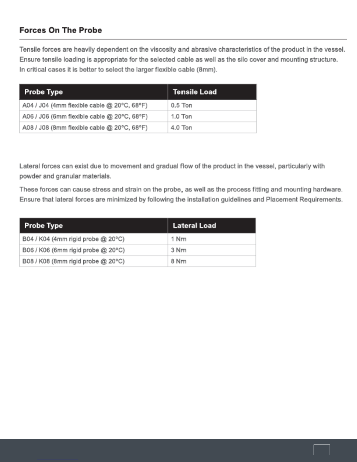
Please read carefully! No liability can be accepted for damage caused by improper use or installation of the Tracer 3000 Level Transmitter.
The Tracer 1000™ 3G Guided Wave Radar Level Transmitter is ideal for level measurement of liquids, solids, bulk
materials, sludge, powders and granules to a distance of 60ft 8 in. Guided-wave technology sends the radar pulse down
a probe to measure either liquids or solids. The pulse hits the surface and is reected back up the probe to the sensor,
where the transit time is translated into a distance using time of ght and time expansion. The amplitude of the reection
depends on the dielectric constant of the product. This technology is not affected by pressure, temperature, viscosity,
vacuum, foam, dust, changes in dielectric constant or coating of the probe.
Safety Precautions
If you are unsure of the suitability of a Tracer 1000™ for your installation, please consult your FLO-CORP representative for
further information.
NOTE: REMOVE ALL PACKING INSERTS BEFORE OPERATING LEVEL TRANSMITTER.
Authorized Personnel
All operations described in this operating instructions manual must be carried out only by trained specialist personnel
authorized by the plant operator. During work on and with the device the required personal protection equipment must
always be worn.
Warning about misuse
Inappropriate or incorrect use of the instrument can give rise to application-specic hazards, e.g. vessel over ll or damage
to system components through incorrect mounting or adjustment.
General Safety Instructions
The user must take note of the safety instructions in this operating instructions manual , the country specic installation
standards as well as all prevailing safety regulations and accident prevention rules. The instrument must only be operated
in a technically awless and reliable condition. The operator is responsible for trouble-free operation of the instrument.
During the entire duration of use, the user is obliged to determine the compliance of the required occupational safety
measures with the current valid rules and regulations and also take note of new regulations.
Disclaimer
The information contained in this document is subject to change without notice. FLO-CORP makes no representations or
warranties with respect to the contents hereof and specically disclaims any implied warranties of merchantability or tness
for a particular purpose.

(877) 356-5463 | (p) 330-331-7331 | (f) 330-331-7172 | www.FLO-CORP.com | © 2018 FLO-CORP | REVA 0918 3(877) 356-5463 | (p) 330-331-7331 | (f) 330-331-7172 | www.FLO-CORP.com | © 2018 FLO-CORP | REVA 0918 4
FEATURES & BENEFITS
• IECEx Ex ia/d [ia Ga] IIC T6 Ga/Gb Tamb 60°C
• IECEx Ex ia tb [ia Da] IIIC T85C Da Db Tamb 60°C
• Up to 60ft 8in (18.5m) range
• Very short minimum range (6", 150mm)
• Simple Setup
• Auto-calibration to any dielectric ≥ 1.5
• Adjustable Sensitivity
• Precise & continuous measurement
• 2-Wire Loop
• 4-20mA, HART Universal / Common practice commands
• Protection class IP66, NEMA 4X
• Measures extremely low dielectric (1.5)
• Programmable fail safe mode
PRIMARY AREAS OF APPLICATION
• Chemical / Petrochemicals
• Energy
• Food & Beverages
• Plastic Pellets
• Minerals & Mining
• Oil & Gas
• Pharmaceutical
• Pulp & Paper
• Wastewater
TECHNOLOGY
The Tracer 1000™3G uses TDR Technology: low-energy, high-frequency electromagnetic impulses, generated by the
sensor’s circuitry, are propagated along the probe which is submerged in the liquid or solid to be measured. When these
impulses hit the surface of the media, part of the impulse energy is reected back up the probe to the circuitry which then
calculates the level from the time difference between the impulses sent and the impulses reected. The sensor can output
the analyzed level as a continuous measurement reading through its analog output. TDR Sensors are also known as Guided
Radars or Guided Wave Radars.

(877) 356-5463 | (p) 330-331-7331 | (f) 330-331-7172 | www.FLO-CORP.com | © 2018 FLO-CORP | REVA 0918 3(877) 356-5463 | (p) 330-331-7331 | (f) 330-331-7172 | www.FLO-CORP.com | © 2018 FLO-CORP | REVA 0918 4
PRIMARY AREAS OF APPLICATION
• Chemical / Petrochemicals
• Energy
• Food & Beverages
• Plastic Pellets
• Minerals & Mining
• Oil & Gas
• Pharmaceutical
• Pulp & Paper
• Wastewater
SPECIFICATION
Specications are subject to change without notice.
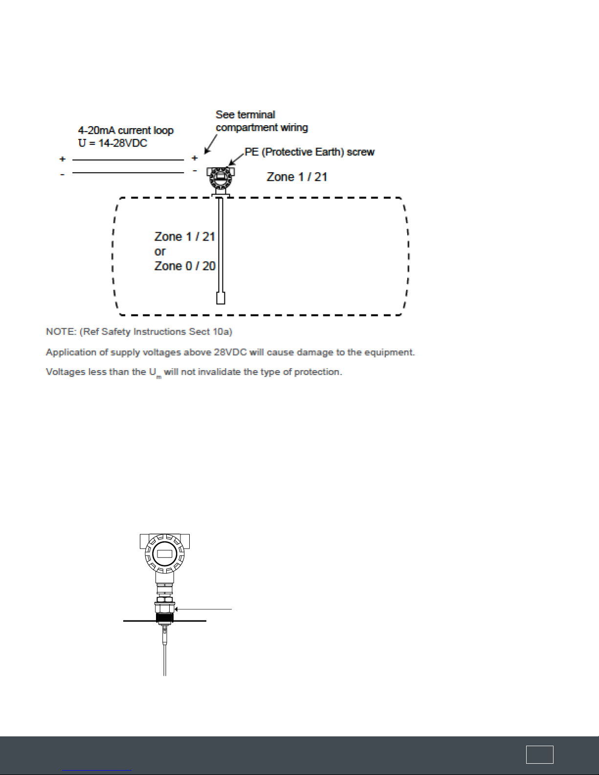
Power 2 wire loop powered
24 VDC (14 to 28 VDC)
Power Consumption <500mW @ 24 Vdc
Analog Output
• 14V @ 0 Ohm
• 19V @ 250 Ohms
• 24V @ 500 Ohms
• Current park at 4mA, 8mA, 12mA
Communications
HART (Revision 5, Universal & Common
Practice commands)
Software via HART. Full parameter list
Maximum Range Flexible cable probe: 60ft 8in
Rigid probe: 13ft 1in
Minimum Range 5.9 inches
Dielectric Range ≥ 1.5
Frequency 2.2 GHz
Resolution Analog: 1uA
Display: 1.0mm
Measurements per
second 3
Response Time <1 second (application dependant)
Sum of non linearity,
non repeatability,
hysteresis
Analog +/- 0.02%
Repeatability +/- 3mm
Memory Non-Volatile (No backup battery required)
>10 years data retention
Operating Temp. Standard: -40 to 176ºF (-40ºC to +80ºC)
Optional: -40 to 608ºF (-40ºC to 320ºC)
Display 4 line graphic display (128 x 64 pixels)
Language English
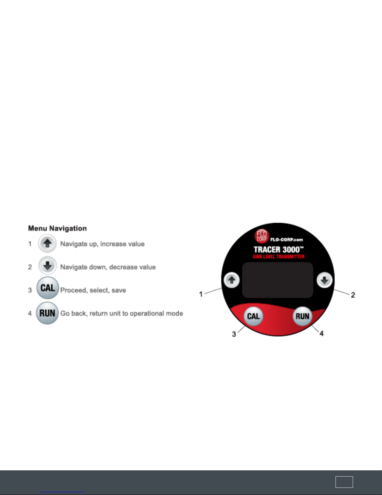
Conguration 4 button (up down, Cal, Run), Software
via HART
Approvals
• IECEx Zone 0/1, Zone 1
IECEx TSA 14.0037X
Ex ia/d [ia Ga] IIC T6 Ga/Gb
Tamb = -40°C to +60°C
IP 66, NEMA 4X
(T6 … T1)
• ATEX Grp II Cat 3 GD IP66 Tamb -40°C
to 60°C
• IECEx Zone 20/21
IECEx TSA 14.0037X
Ex ia tb [ia Da] IIIC T85°C Da Db
Tamb = -40°C to +60°C
IP 66, NEMA 4X
• FM Approvals Pending
Electromagnetic
Compatibility
WIRING COMPARTMENT DIMENSIONS
AB

(877) 356-5463 | (p) 330-331-7331 | (f) 330-331-7172 | www.FLO-CORP.com | © 2018 FLO-CORP | REVA 0918 5(877) 356-5463 | (p) 330-331-7331 | (f) 330-331-7172 | www.FLO-CORP.com | © 2018 FLO-CORP | REVA 0918 6
DISPLAYED DIAGNOSTICS
SETUP MENU
While pressing the arrow buttons, the top corner of the display cycles through various unit diagnostics
DISPLAYED DIAGNOSTICS
mA Simulated current output in mA
NORMAL Unit operating normally
FAILED Unit in failsafe conditions
RECOVER Unit searching for level / attempting
to amplify signal
LEVEL-1 Upper Material Level Meausrement
LEVEL-2 Lower Material Level Meausrement
PARAMETER DESCRIPTION OPTIONS
DISPLAY MODE Select default display mode
Volume(2)
Level
%Level
Distance
DISPLAY UNIT Adjust displayed measurement unit
Centimeters
Metres
Feet
Inches
LOW LEVEL Set Low Level (4mA) distance Adjustable
HI LEVEL Set High Level (20mA) distance Adjustable
DAMPING Adjust output response time & smoothness Adjustable
TRACKING
Program application Fill and Empty speeds.
Fast (90m/h, 265ft/h.) Medium (30m/h, 98ft/h), Slow (10m/h,
32ft/h).
InstaTrack is a special mode which we respond immediately
to any detected reflection.
‘Test’ Mode adjusts unit function to be suitable for bench
testing and demonstration. The unit will track nearest detected
reflection regardless of size.
•Fast
•Medium
•Slow
•InstaTrack
•Test
DIELECTRIC Applies a pre-set value to sensitivity based on selected
Dielectric Constant range of material.
•<2 •<2 5
•<10 •<20
•<40 •<80
•> 80

(877) 356-5463 | (p) 330-331-7331 | (f) 330-331-7172 | www.FLO-CORP.com | © 2018 FLO-CORP | REVA 0918 5(877) 356-5463 | (p) 330-331-7331 | (f) 330-331-7172 | www.FLO-CORP.com | © 2018 FLO-CORP | REVA 0918 6
The ‘Digitize’ function is an automatic setup routine to create a digital map of false echoes generated by
problems such as non-recommended mounting.
The function should be performed after physical installation to the application.
During the process the unit will prompt a measured distance (this must be either the material level if material
is touching the probe, or end of probe of the vessel is empty. For Interface model type it must be the Upper
Layer). The distance is adjustable if the displayed distance is not correct.
Ensure the value is not greater than the distance to the material level.
For best results follow this routine:
1) Ensure the unit is mounted according to mounting specications and requirements.
2) Ensure the material to be measured is in contact with the actively measured part of the probe.
3) Select Dielectric pre-set value of most similar to material to be measured. For Interface model type it must
be the Upper Layer).
4) Run Digitize routine. Conrm displayed distance is either material level.
FAIL MODE Set Failsafe reading
3.80mA
>20.20mA
LastKnown
4mA
20.00mA
>21.50mA
FAIL TIME Set time delay for FailSafe condition (in seconds) Adjustable
DIGITIZE
The ‘Digitize’ function is an automatic setup routine used to
eliminate false reflections. See ‘Digitze Function’ for further
information.
•No
•Yes
•Disable
DIGITIZE FUNCTION
ADVANCED MENU
PARAMETER DESCRIPTION OPTIONS
COMMS Adjust communication protocol settings. The default ID is 0,
and the default baud rate is 1200
•Device ID
•Baud Rate
SENSITIVITY
Manual adjustment of Sensitivity. Dieletric selection
automatically sets this value to defaults based on the Dieletric
selection. Sensitivity is the primary adjustment for the unit’s
ability to detect media. A higher value is used for lower Dk
materials or more difficult applications
•0-100
BLANKING Blanking is a non-measurable zone. This can be increased to
‘Blank’ out high level false echoes caused by mounting
Adjustable
<150mm
(6”) is not
recommended

(877) 356-5463 | (p) 330-331-7331 | (f) 330-331-7172 | www.FLO-CORP.com | © 2018 FLO-CORP | REVA 0918 7(877) 356-5463 | (p) 330-331-7331 | (f) 330-331-7172 | www.FLO-CORP.com | © 2018 FLO-CORP | REVA 0918 8
ANALOG
Adjust Analog output. Switch from 4-20mA to 20-4mA
Fine tune both 4mA current and 20mA current reading
Park (Lock) Current to 4, 8 or 12mA.
• 4-20
• 20-4
• 4mA tuning
• 20mA tuning
• Park 4mA
• Park 8mA
• Park 12mA
INTERFACE(1) Enable / Disable Interface measurement mode. See ‘Interface
Mode’ for more information
Enable /
Disable
FACTORY RESET Restore all parameters to factory default. • Yes
• No
DEVICE INFO Display device information
•<2 •<2 5
•<10 •<20
•<40 •<80
•> 80
LOCK CODE Enable / Disable lock code. If enabled, select lock code
number.
Enable /
Disable
PROBECALIBR
If physical length of probe is adjusted you must run this
routine for the system to re-detect the probe end. Nothing
should be touching the probe when commencing this function.
• Adjustable
• Password
protected
(222)
PROBEFAULT Probe Fault will activate Failsafe in the event of a missing
Probe
Enable /
Disable
DIST CALIBR
Calibrate distance correction factor. Some applications or
environments can affect time of flight signal travel affecting
the measured distance reading. This function allows the
detected distance to be adjusted to suit the application.
Adjustable
(1)Interface mode is only available with the Interface communications option (see Part Numbers)
INTERFACE MODE SETUP
Interface mode is only avaialble with the Interface communications option (see Part Numbers).
The Interface mode is designed to measure applications with low to high dielectric constant layers.
The transmited signal relfects off the Upper Layer and continues through the Interface and reects from the
Lower Layer.
The unit provides a level reading for both the Upper and Lower Layers available via HART. The Lower Layer
will always be transmitted to the 4-20mA output.
When Interface mode is Enabled, the following parameters are adjustable.
PARAMETER DESCRIPTION OPTIONS
DK COMP Set dielectric of interface layer. This adjusts the velocity compensation for the
transmitted signal as it passes through the interface. Default 2.22 0-100

(877) 356-5463 | (p) 330-331-7331 | (f) 330-331-7172 | www.FLO-CORP.com | © 2018 FLO-CORP | REVA 0918 7(877) 356-5463 | (p) 330-331-7331 | (f) 330-331-7172 | www.FLO-CORP.com | © 2018 FLO-CORP | REVA 0918 8
IFACE WIDTH
Set water reading (level 2) offset in the event of a merged echo. A merged echo
will occur if the interface is too thin to produce a separate echo. The offset is
measured from the end of the merged echo backwards. Default 150mm (0.5ft)
Note: This is an advanced setting and should not be adjusted without expert
knowledge
Adjustable
IFACE SIZE
Sets the echo size (in signal voltage) to dictate whether an echo is from the
Interface or Level. If the echo is larger than the value the unit will assume no
Interface is present and will set Level 1 reading to be the same as Level 2 reading.
If the echo is smaller it will assume there is only an Interface layer measurable and
will set Level 2 to end of probe measurement. Default 2.34
Note: This is an advanced setting and should not be adjusted without expert
knowledge
0-2.49
COMMISSIONING
PARAMETER INSTRUCTION
1. SET INTERFACE MODE If the application is NOT an interface application, disable interface mode.
2. SET HIGH AND LOW
LEVEL
High and Low level distances can be programmed manually or you can run
Autoset. Autoset can be used to program the High or Low level based on the
material level which is touching the probe when the function is run.
3. SET TRACKING
SPEEDS
Tracking speeds can be set to Fast, Medium, Slow and Custom (measured in
Displayed Units per hour)
4. SELECT DIELECTRIC Choose closest Dielectric range of Upper material Level from the pre-set list.
Select lower value if unsure. <2 will be appropriate for most Interface applications.
5. RUN DIGITIZE
Confirm displayed distance is either material level (for Interface applications
it must be the Upper Layer) or end of probe if vessel is empty.
Ensure the value is not greater than the distance to the material level.
See ‘Digitize Function’ for additional critical information.
6. SET DK
COMPENSATION Program Dielectric value of Upper Material Layer in Interface Menu
7. ADD DAMPING Increasing Damping value if a smoother response trend is required. This
value is automatically set by the Tracking speed.
8. RUN UNIT Press RUN several times to commence unit operation
(877) 356-5463 | (p) 330-331-7331 | (f) 330-331-7172 | www.FLO-CORP.com | © 2018 FLO-CORP | REVA 0918 9
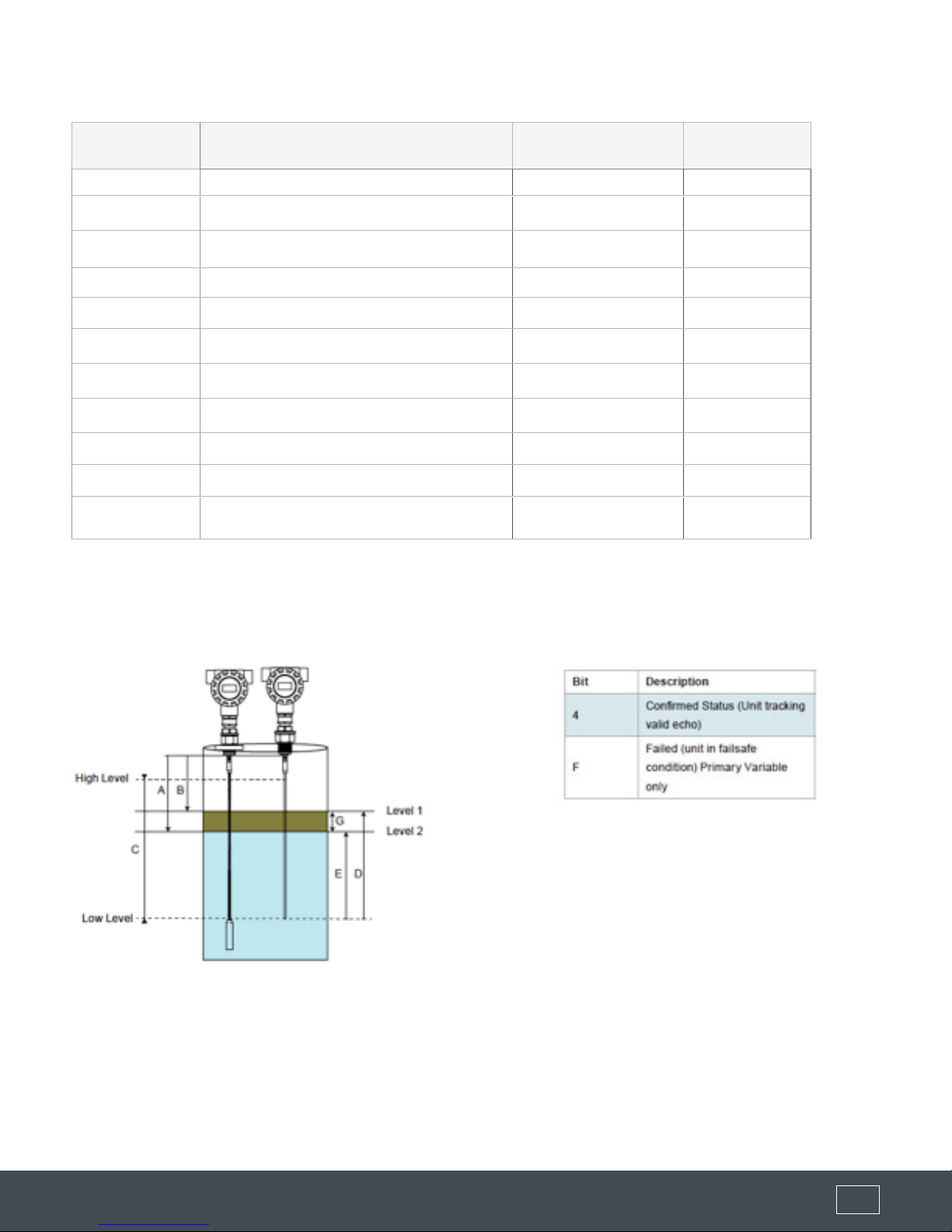
REGISTERS
ADDRESS VARIABLE / DESCRIPTION CONVERSION TO FEET MEASUREMENT
REFERENCE
720 Primary Variable (Level 2 Level in mm) Div. by 304.7851 E
721 Secondary Variable (Level 1 Level in mm) Div. by 304.7851 D
722 Tertiary Variable (interface Height in mm) Div. by 304.7851 G
723 Low Level (mm) Div. by 304.7851
724 High Level (mm) Div. by 304.7851
725 Primary Variable Status
726 Primary Variable (Level 2 Distance in mm) Div. by 304.7851 A
727 Primary Variable Percentage C
728 Secondary Status
729 Secondary Variable (Level 1 Distance in mm) Div. by 304.7851
730 Secondary Variable Percentage C
MEASUREMENT REFERENCE STATUS BIT MAPPING

(877) 356-5463 | (p) 330-331-7331 | (f) 330-331-7172 | www.FLO-CORP.com | © 2018 FLO-CORP | REVA 0918 10 (877) 356-5463 | (p) 330-331-7331 | (f) 330-331-7172 | www.FLO-CORP.com | © 2018 FLO-CORP | REVA 0918 11 (877) 356-5463 | (p) 330-331-7331 | (f) 330-331-7172 | www.FLO-CORP.com | © 2018 FLO-CORP | REVA 0918 12 (877) 356-5463 | (p) 330-331-7331 | (f) 330-331-7172 | www.FLO-CORP.com | © 2018 FLO-CORP | REVA 0918 13 (877) 356-5463 | (p) 330-331-7331 | (f) 330-331-7172 | www.FLO-CORP.com | © 2018 FLO-CORP | REVA 0918 14 (877) 356-5463 | (p) 330-331-7331 | (f) 330-331-7172 | www.FLO-CORP.com | © 2018 FLO-CORP | REVA 0918 15
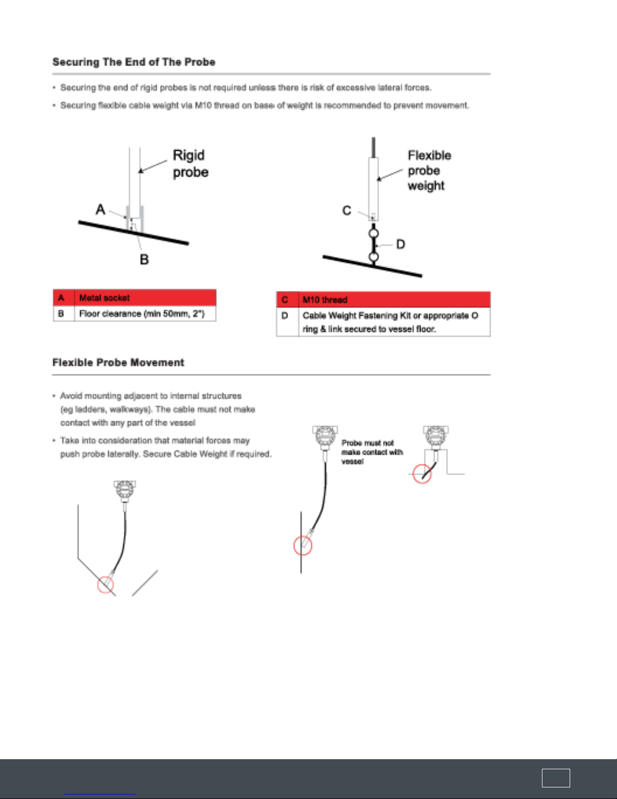
Instructions for Assembling Detached Probe Handling and Mounting:
(877) 356-5463 | (p) 330-331-7331 | (f) 330-331-7172 | www.FLO-CORP.com | © 2018 FLO-CORP | REVA 0918 10 (877) 356-5463 | (p) 330-331-7331 | (f) 330-331-7172 | www.FLO-CORP.com | © 2018 FLO-CORP | REVA 0918 11 (877) 356-5463 | (p) 330-331-7331 | (f) 330-331-7172 | www.FLO-CORP.com | © 2018 FLO-CORP | REVA 0918 12 (877) 356-5463 | (p) 330-331-7331 | (f) 330-331-7172 | www.FLO-CORP.com | © 2018 FLO-CORP | REVA 0918 13 (877) 356-5463 | (p) 330-331-7331 | (f) 330-331-7172 | www.FLO-CORP.com | © 2018 FLO-CORP | REVA 0918 14 (877) 356-5463 | (p) 330-331-7331 | (f) 330-331-7172 | www.FLO-CORP.com | © 2018 FLO-CORP | REVA 0918 15
Wiring in Hazardous Locations
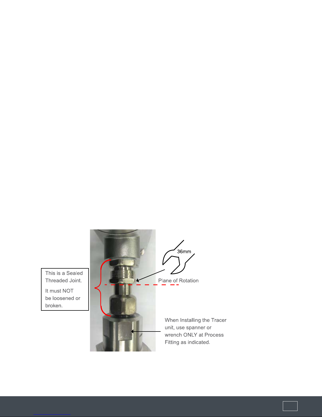
Mounting - Instruction for Rotating the Housing
• There are specic rotation points which should be used while mounting the unit into place.
• The Housing Compartment should never be used to rotate the device during mounting.
• For rotating the housing after installation see 'Rotating the Enclosure' section.
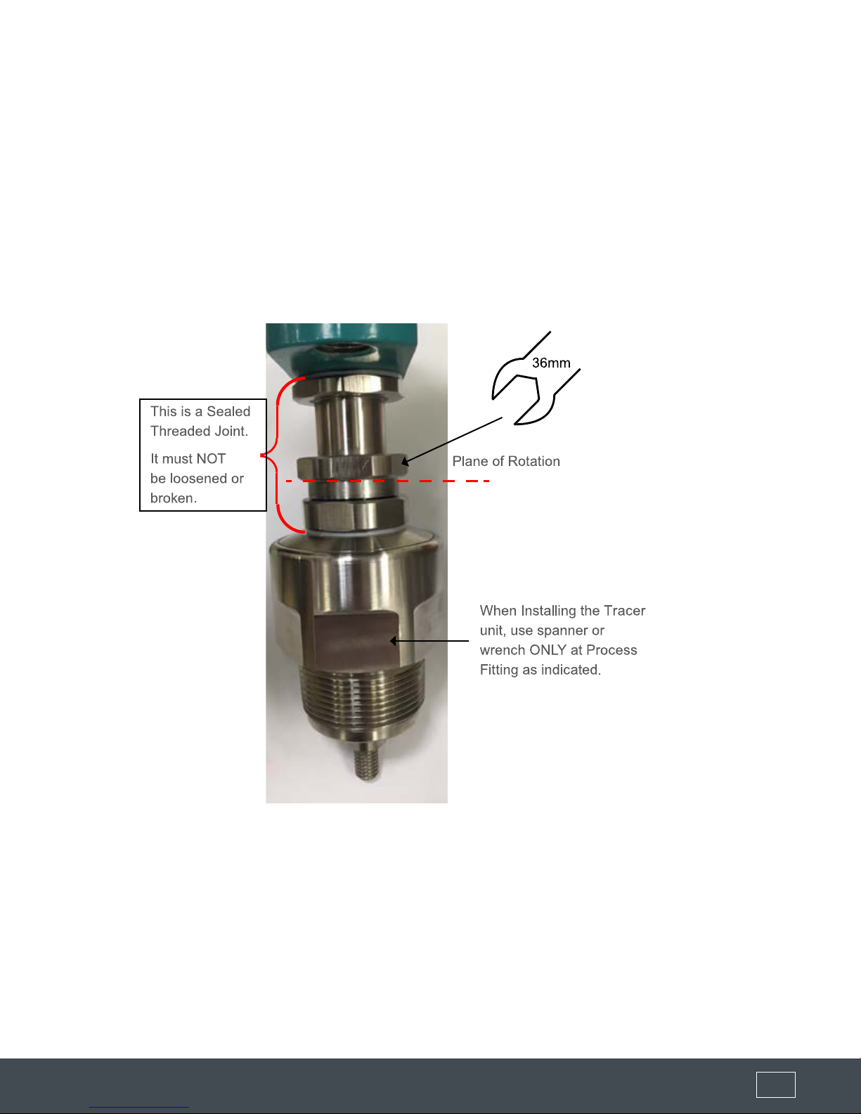
When Installing the Tracer 3000 unit, use spanner or
wrench ONLY at Process Fitting as indicated.
(877) 356-5463 | (p) 330-331-7331 | (f) 330-331-7172 | www.FLO-CORP.com | © 2018 FLO-CORP | REVA 0918 10 (877) 356-5463 | (p) 330-331-7331 | (f) 330-331-7172 | www.FLO-CORP.com | © 2018 FLO-CORP | REVA 0918 11 (877) 356-5463 | (p) 330-331-7331 | (f) 330-331-7172 | www.FLO-CORP.com | © 2018 FLO-CORP | REVA 0918 12 (877) 356-5463 | (p) 330-331-7331 | (f) 330-331-7172 | www.FLO-CORP.com | © 2018 FLO-CORP | REVA 0918 13 (877) 356-5463 | (p) 330-331-7331 | (f) 330-331-7172 | www.FLO-CORP.com | © 2018 FLO-CORP | REVA 0918 14 (877) 356-5463 | (p) 330-331-7331 | (f) 330-331-7172 | www.FLO-CORP.com | © 2018 FLO-CORP | REVA 0918 15
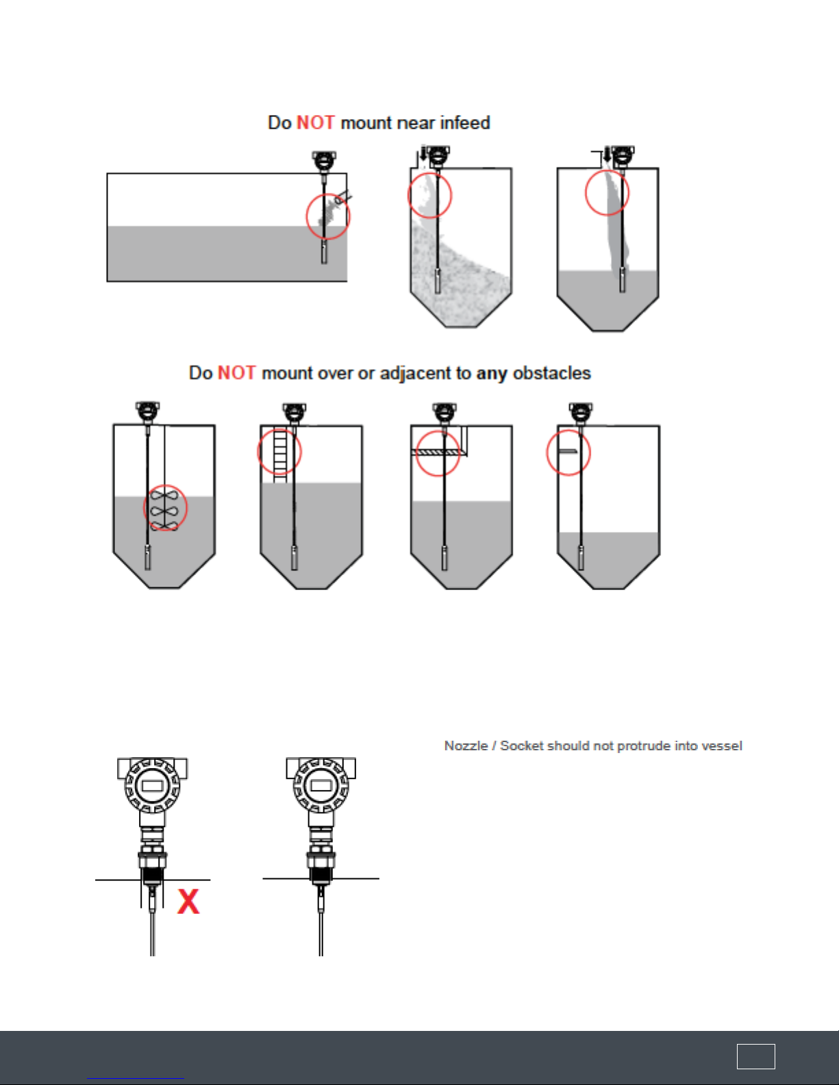
Placement Requirements
Nozzle / Socket Mounting

(877) 356-5463 | (p) 330-331-7331 | (f) 330-331-7172 | www.FLO-CORP.com | © 2018 FLO-CORP | REVA 0918 10 (877) 356-5463 | (p) 330-331-7331 | (f) 330-331-7172 | www.FLO-CORP.com | © 2018 FLO-CORP | REVA 0918 11 (877) 356-5463 | (p) 330-331-7331 | (f) 330-331-7172 | www.FLO-CORP.com | © 2018 FLO-CORP | REVA 0918 12 (877) 356-5463 | (p) 330-331-7331 | (f) 330-331-7172 | www.FLO-CORP.com | © 2018 FLO-CORP | REVA 0918 13 (877) 356-5463 | (p) 330-331-7331 | (f) 330-331-7172 | www.FLO-CORP.com | © 2018 FLO-CORP | REVA 0918 14 (877) 356-5463 | (p) 330-331-7331 | (f) 330-331-7172 | www.FLO-CORP.com | © 2018 FLO-CORP | REVA 0918 15
Stand Pipe / Flanged Mounting
(877) 356-5463 | (p) 330-331-7331 | (f) 330-331-7172 | www.FLO-CORP.com | © 2018 FLO-CORP | REVA 0918 10 (877) 356-5463 | (p) 330-331-7331 | (f) 330-331-7172 | www.FLO-CORP.com | © 2018 FLO-CORP | REVA 0918 11 (877) 356-5463 | (p) 330-331-7331 | (f) 330-331-7172 | www.FLO-CORP.com | © 2018 FLO-CORP | REVA 0918 12 (877) 356-5463 | (p) 330-331-7331 | (f) 330-331-7172 | www.FLO-CORP.com | © 2018 FLO-CORP | REVA 0918 13 (877) 356-5463 | (p) 330-331-7331 | (f) 330-331-7172 | www.FLO-CORP.com | © 2018 FLO-CORP | REVA 0918 14 (877) 356-5463 | (p) 330-331-7331 | (f) 330-331-7172 | www.FLO-CORP.com | © 2018 FLO-CORP | REVA 0918 15
Mounting - Conductive Vessel
Unit performance is most optimized when there is a ground reference between the mounting
(metal ange or thread) and the vessel. Metallic or metal reinforced vessels are ideal.
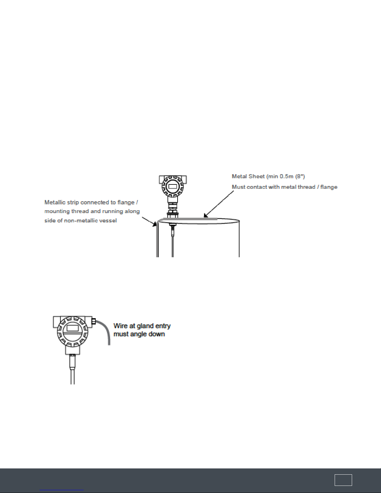
Mounting - Non Conductive Vessel
A non conductive vessel will require a conductive metal strip or equivalent connected to the
metal ange or thread and running along side the vessel for at least the Probe insertion length.
A conductive metal sheet (min 0.5m (8") should also be mounted on the roof and be in contact
with metal thread or ange. If a seal / gasket is used between the ange and the vessel ensure
non coated / painted bolts are used to create ground reference with vessel.
Gland Entry Wiring
(877) 356-5463 | (p) 330-331-7331 | (f) 330-331-7172 | www.FLO-CORP.com | © 2018 FLO-CORP | REVA 0918 10 (877) 356-5463 | (p) 330-331-7331 | (f) 330-331-7172 | www.FLO-CORP.com | © 2018 FLO-CORP | REVA 0918 11 (877) 356-5463 | (p) 330-331-7331 | (f) 330-331-7172 | www.FLO-CORP.com | © 2018 FLO-CORP | REVA 0918 12 (877) 356-5463 | (p) 330-331-7331 | (f) 330-331-7172 | www.FLO-CORP.com | © 2018 FLO-CORP | REVA 0918 13 (877) 356-5463 | (p) 330-331-7331 | (f) 330-331-7172 | www.FLO-CORP.com | © 2018 FLO-CORP | REVA 0918 14 (877) 356-5463 | (p) 330-331-7331 | (f) 330-331-7172 | www.FLO-CORP.com | © 2018 FLO-CORP | REVA 0918 15
(877) 356-5463 | (p) 330-331-7331 | (f) 330-331-7172 | www.FLO-CORP.com | © 2018 FLO-CORP | REVA 0918 16 (877) 356-5463 | (p) 330-331-7331 | (f) 330-331-7172 | www.FLO-CORP.com | © 2018 FLO-CORP | REVA 0918 17 (877) 356-5463 | (p) 330-331-7331 | (f) 330-331-7172 | www.FLO-CORP.com | © 2018 FLO-CORP | REVA 0918 18 (877) 356-5463 | (p) 330-331-7331 | (f) 330-331-7172 | www.FLO-CORP.com | © 2018 FLO-CORP | REVA 0918 19
Adjusting Probe Length
Rigid Probes
Cut rigid probes to appropriate length. After adjustment, you must change the 'ProbeLength' Parameter in 'Advanced'
menu to represent the new length (password 222).
Flexible Probes
(a) Mark the point at which the exible cable enters the cable weight.
(b) Release the cable weight grub screws with hex key.
(c) Measure and note the length of cable concealed within cable weight.
(d) Cut cable noting the length of cable must include the concealed length above.
(e) Re-insert the cable into the weight and tighten grub screws to tightening Torque of 20Nm. Use loctite 243 or
equivalent on grub screws to secure once completed.
(f) Adjust ProbeCalibr Parameter in 'Advanced' menu to represent new length (password 222).
Rotating Ex Rated Enclosures
The Ex d gland which couples the sensing probe to the ameproof enclosure provides a critical sealing
function for the enclosure. Internal wires are passed through this gland and the high integrity seal. This
gland
incorporates a Union Joint which is designed to rotate.
However, this rotation is limited to one-time adjustment of Display orientation after installation on site.
ONLY one 36mm spanner applied to the Hex of Union Joint to rotate enclosure to desired orientation as
allowed. DO NOT hold the enclosure during this procedure.
Rotation beyond these strict limits can damage the internal cables
Ensure Enclosure follows the spanner rotation and assembly integrity is not compromised
The gland which couples the sensing probe to the enclosure provides a critical sealing function
for the enclosure. Internal wires are passed through this gland and the high integrity seal. This
gland incorporates a Union Joint which is designed to rotate.
However, this rotation is limited to one-time adjustment of Display orientation after installation on
site.
ONLY one 36mm spanner applied to the Hex of Union Joint to rotate enclosure to desired orien-
tation as allowed. DO NOT hold the enclosure during this procedure.
Rotation beyond these strict limits can damage the internal cables
Ensure Enclosure follows the spanner rotation and assembly integrity is not compromised
(877) 356-5463 | (p) 330-331-7331 | (f) 330-331-7172 | www.FLO-CORP.com | © 2018 FLO-CORP | REVA 0918 16 (877) 356-5463 | (p) 330-331-7331 | (f) 330-331-7172 | www.FLO-CORP.com | © 2018 FLO-CORP | REVA 0918 17 (877) 356-5463 | (p) 330-331-7331 | (f) 330-331-7172 | www.FLO-CORP.com | © 2018 FLO-CORP | REVA 0918 18 (877) 356-5463 | (p) 330-331-7331 | (f) 330-331-7172 | www.FLO-CORP.com | © 2018 FLO-CORP | REVA 0918 19
Rotating non Ex Rated Enclosures
The gland which couples the sensing probe to the enclosure provides a critical sealing function
for the enclosure. Internal wires are passed through this gland and the high integrity seal. This
gland incorporates a Union Joint which is designed to rotate.
However, this rotation is limited to one-time adjustment of Display orientation after installation on
site.
ONLY one 36mm spanner applied to the Hex of Union Joint to rotate enclosure to desired orien-
tation as allowed. DO NOT hold the enclosure during this procedure.
Rotation beyond these strict limits can damage the internal cables
Ensure Enclosure follows the spanner rotation and assembly integrity is not compromised
(877) 356-5463 | (p) 330-331-7331 | (f) 330-331-7172 | www.FLO-CORP.com | © 2018 FLO-CORP | REVA 0918 16 (877) 356-5463 | (p) 330-331-7331 | (f) 330-331-7172 | www.FLO-CORP.com | © 2018 FLO-CORP | REVA 0918 17 (877) 356-5463 | (p) 330-331-7331 | (f) 330-331-7172 | www.FLO-CORP.com | © 2018 FLO-CORP | REVA 0918 18 (877) 356-5463 | (p) 330-331-7331 | (f) 330-331-7172 | www.FLO-CORP.com | © 2018 FLO-CORP | REVA 0918 19
(877) 356-5463 | (p) 330-331-7331 | (f) 330-331-7172 | www.FLO-CORP.com | © 2018 FLO-CORP | REVA 0918 16 (877) 356-5463 | (p) 330-331-7331 | (f) 330-331-7172 | www.FLO-CORP.com | © 2018 FLO-CORP | REVA 0918 17 (877) 356-5463 | (p) 330-331-7331 | (f) 330-331-7172 | www.FLO-CORP.com | © 2018 FLO-CORP | REVA 0918 18 (877) 356-5463 | (p) 330-331-7331 | (f) 330-331-7172 | www.FLO-CORP.com | © 2018 FLO-CORP | REVA 0918 19
Installation should only be performed by suitably qualied personnel.
A. Conrm mounting is within recommended specications.
B. Check the selected unit matches the required application specications.
For Hazardous Locations see appropriate safety instructions available at http://www.FLO-CORP.com
C. Check the wiring is correct and all connections are secure.
D. Apply power to the unit.
When power is applied the unit will start its normal load sequence.
The following messages will cycle on the display.
When power is applied the unit will start its normal load sequence.
The following messages will cycle on the display.
FLO-CORP
Tracer 3000 Series
Serial Number
Software Revision

(877) 356-5463 | (p) 330-331-7331 | (f) 330-331-7172 | www.FLO-CORP.com | © 2018 FLO-CORP | REVA 0918 20 (877) 356-5463 | (p) 330-331-7331 | (f) 330-331-7172 | www.FLO-CORP.com | © 2018 FLO-CORP | REVA 0918 21
Table of contents
Popular Transmitter manuals by other brands

FlowLine
FlowLine EchoWave LG10 Series manual

Micro Seven
Micro Seven VM10a Operator's manual

Harmonic
Harmonic SUPRALink 7110-E Series installation guide

Genius
Genius 450 quick start guide

Williams Sound
Williams Sound SoundPlus WIR TX10 Installation guide & user manual

Monte Carlo Fan Company
Monte Carlo Fan Company ESSWC-10 Installation and operation instruction


ENERGY SISTEM
ENERGY SISTEM FM BT PRO user manual

Bosch
Bosch RFKF-FB installation manual

Rice Lake
Rice Lake SCT-1SX-MODBUS TCP/IP quick start guide

Greystone Energy Systems
Greystone Energy Systems TDAP Series installation instructions

WIKA
WIKA T19.10 operating instructions

M-system
M-system M2LR instruction manual