Micro Seven VM10a User manual

1
OPERATOR’S MANUAL
MODEL VM10A
Micro Seven, Inc.
1095-K N.E. 25th Hillsboro, OR 97124 U.S.A.
phone: 503-693-6982
fax: 503-693-9742
www.microseveninc.com
Copyright, 2019 by Micro Seven, Inc. All right reserved.
Contents of this publication may not be reproduced in any form without the written
permission of Micro Seven, Inc.
All requests for repairs should be directed to the factory.
This instrument is warranted against defective workmanship and materials for a period of
six months. There will be no warranty when the instrument is misused, or when the
factory seal on the instrument is broken.
Printed in U.S.A.
Specification and price change privileges are reserved.

2
Index
Chapter 1 Introduction/Features
Chapter 2 Specifications
Chapter 3 First time operation/Installation
Chapter 4 Basic measurement with app
Chapter 5 Changing voice segment
Chapter 6 Changing Auto Start Timer
Chapter 7 Downloading Factory Default Voice Segment
Chapter 8 Calibration
Chapter 9 DMM data and trace history files
Chapter 10 Stand-alone operation
Chapter 11 Troubleshooting

3
Chapter 1
Introduction/Features
Micro Seven, Inc. 's model VM10a or VM10ac is a peripheral device that transmits
measurement result to BLE controller like a smartphone. After an app is opened, VM10a
connects to a BLE controller automatically when the device ID on the app matches with VM10a
device ID. The device ID is a 4-digit code that is unique to each VM10a.
When the app is closed, BLE connection is turned off. When the app is opened again, “Restart”
or “scanning” button is required to be pushed. VM10a and BLE controller or smartphone app
provide remote measurement of DMM functions and oscilloscope via wireless BLE. Received
data and/or trace information may be stored in the BLE controller by manually or automatically.
Various trigger methods, viewing of past test results and multi-colored traces, and isolated
common signals help engineers and technicians for testing electronic circuits.
The stand-alone measurement mode includes voice-trigger mode for starting A/D with audio
input through a built-in microphone, value-change mode for starting A/D automatically for input
exceeding certain value and continuous mode. VM10's voiced measurement data output
eliminates looking of display data on conventional display. The value-change mode provides
automatic voiced data without looking at a display area. Each voice segment of numerical and
legend voice segments is programmable through a built-in microphone. An audio speaker is
built-in in VM10A. Lower cost VM10ac for no voice output nor stand-alone operation is available.
Features
- Voiced measurement data output for DC Volt, AC Volt, and resistance
- Oscilloscope function with various trigger modes and time base change (App)
- Almost unlimited amount of measurement data output and oscilloscope data (App)
- Stand-alone or using smartphone App mode
- Measurement data output to smart phones wirelessly
- Programmable voice segments (App)
-Remote measurement of digital multi-meter and oscilloscope via BLE wireless and smart phone
app
-Manual or automatic start/time interval mode and recording data/traces
-Voiced measurement data output for DC Volt, AC Volt, and resistance in your own voice
-Floated power supply measurement
-optional internal rechargeable battery

4
MICRO SEVEN-Model VM10a, Scope-Meter, oscilloscope/Talking Digital Multi-meter is shown
in above picture. The rear view of VM10a is shown below.

5

6
Screenshot of eight traces of input voltage at different times applied at VM10a by smart-phone
app is shown below. The time setup is 50 μs /div. The vertical setup is 0.5V/div with 0V at its
center. The triggering is set as “Free Run”. The trigger level that may be changed by swiping up
or down is shown as a red-dotted line. Number of color traces is changed among 1-8 colors.

7
Chapter 2
Specifications
Device ID: 4-digit alphanumeric like “DD29”
Note: The BLE connection to BLE controller and data communication require matching of the
programmed Device ID in the app and Device ID that is advertised by VM10a.
Stand-alone mode (only for VM10a):
- Value trigger mode to do automatic measurement with Microphone-triggered measurement
- No need to look measurement display anymore
- Continuous measurement
Input amplifier bandwidth: 125kHZ
Maximum sample rate for trace/oscilloscope measurement: 250kHZ
Measurement ranges:
DC volt and RMS: +/-200mV, +/-2.000V, +/- 20.00V, +/- 200.0V, +/- 500V, +/- 1 % (for DC volt),
and +/- 3% for 50Hz to 5 kHZ in RMS measurement
Oscilloscope input range: same as DC volt except +/-100mV, +/-1.000V, +/- 10.00V, +/- 100.0V,
+/- 500V for battery option
Resistance: 2.000k ohm, 20.00k ohm, 200k ohm, 2.000meg ohm, +/- 5%
True-RMS measurement including DC+AC component
Measurement inputs:
VM10a: three banana jacks (Red, Black, and Blue)
J1 (Red ): + input terminal
J2 (Black): – input terminal
J3(Blue): AC coupled input terminal
VM10ac: two banana jacks (Red and Black)
J1(Red) + input terminal
J2(Blac)k: – input terminal
Common input may be elevated up to +/- 120VRMS with respective to the earth ground with
chassis-ground isolated AC/DC power adapter.
Front-panel controls:
Built-in microphone (only for VM10a)
SW 1 (left), Mode switch, short push for announcing current mode, longer push to change to
next mode (only for VM10a):

8
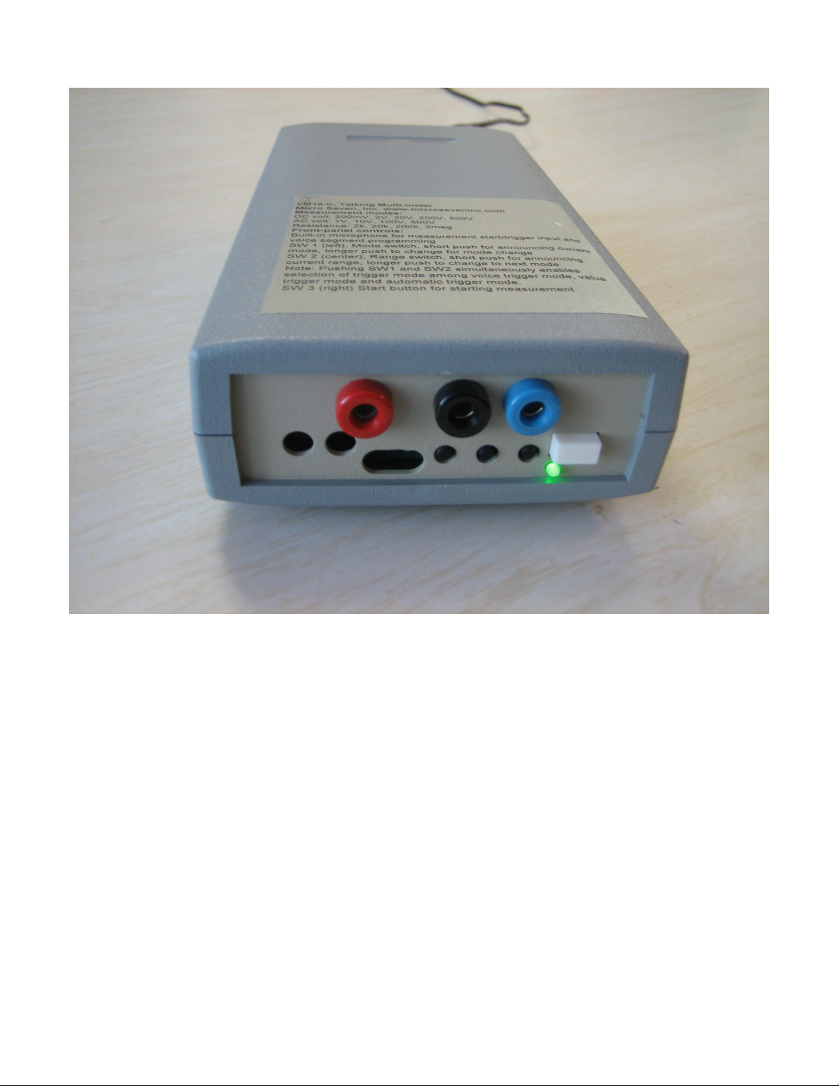
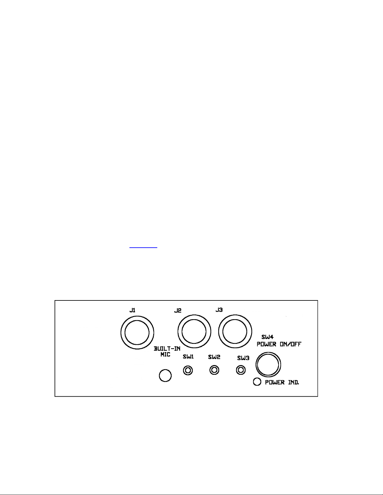
SW 2 (center), Range switch, short push for announcing current range, longer push to change
to next mode (only for VM10a)
Note: Pushing SW1 and SW2 simultaneously will place into mode-programming.
SW 3 (right) Start button for manual push button for starting voiced measurement (only for
VM10a):
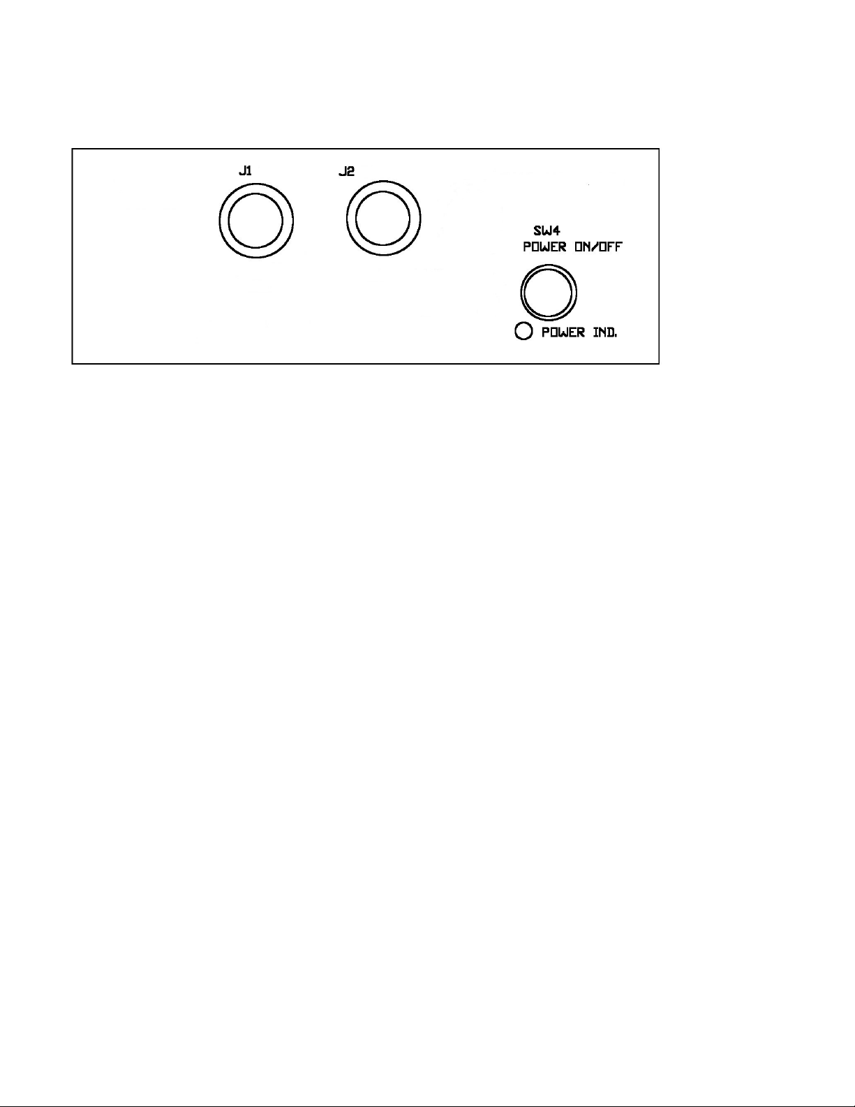
SW4: power on/off switch
Power indicator, steady when the power is on, or flashing when BLE connection is made.
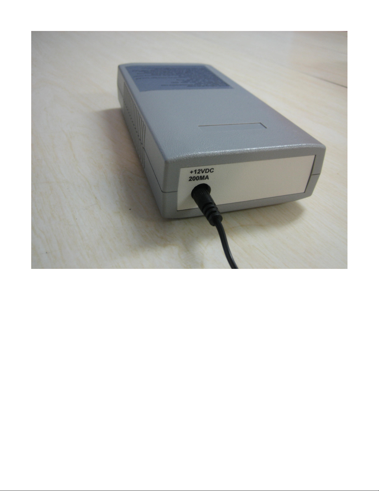
Rear panel:
12VDC input connector (from 117V AC/DC adapter)
Time base: 100ms/div, 50ms/div, 20ms/div, 10ms/div, 5ms/div, 2ms/div, 1ms/div, 0.5ms/div,
0.2ms/div, 0.1ms/div, 50 μs/div, or 20 μs/div where ‘TB<’ for slower time base (maximum
100ms) or ‘TB>’ for faster time base (minimum 20 μs)
Voice Generation/Recording in factory-default voice or in your own voice (only for
VM10a)
Note: voice announcement of measurement is done by audio speaker in DM10a not by
audio speaker in smartphones.
Downloading factory default voice file is available in the app. Note: VM10a is also loaded with
the factory default voice file.
Numerical voice data-0.5 seconds: 0,1,2,3,4,5,6,7,8,9, decimal point, over-range indicator, and
minus sign
2 seconds voice data: Unit of measurement (DC volt, AC volt, kilo-ohm, and meg -ohm)
Audio output is output via built-in speaker.
Wireless standard: IEEE 802.15.1 transparent UART operation, BLE operation
Optional battery operation with Ni-Cad battery pack:
Power: 2.5 hours of battery operation
Recharging time: 24 hours
Charge/discharge cycles: 100 times minimum
AC/DC Adapter and battery charger: 12VDC unregulated, 800mA maximum with 117VAC
input power

9
Factory hardware reset: pushing power switch while pushing SW2 and release SW2
Warning: the factory hardware reset requires the calibration procedure in Chapter 8.
Dimensions: 19 cm (4") W x 4.5 cm (1.75") H x 10 cm (7.5") L
Weight: 500g (1.1 lbs.)
Environmental: Operating temperature: 0 to 35 degree C, Humidity: 85% RH at 35 degree C
Warranty/Service: one year limited warranty. No warranty if any factory seal is broken. Service
is performed at the factory.
Calibration procedure: included in the app, description in Chapter 8 in this manual
Models available: VM10a, VM10ac, or VM10
VM10 is for stand-alone operation with RS232c interface instead of smartphone wireless
operation.
Optional features:
1. International AC/DC power adapter for 90-250VACRMS and 50/60Hz power input
2. Car battery adapter
3. Rechargeable battery
4. Order lower-priced VM10ac, which is not for stand-alone operation and does not
include voiced measurement nor speaker.
Front panel of VM10a is shown above.

10
The front panel of VM10ac is shown below:

11
Chapter 3
First-time Operation/Installation
The smartphone setting on the Bluetooth must be on. If it is off, change to on. When it
was off, see the troubleshooting in Chapter 11.
Connect a provided AC/DC power adapter to proper AC power input and connect the input
power connector to a power input jack of VM10a.
Turn on the power switch of VM10a confirm that green LED on the front panel of VM10a is on.
Note that the LED continuously blinks when VM10a and smartphone are connected via the
wireless standard.
Open VM10a app on the smartphone.
After few seconds, the screen will show very similar like the following:
Received: VM10_D2D9
The device ID does not match with received device ID.
Enter the correct 4-digit Device ID after “_” above
In the text field shown ‘D2D9’.
Close and reopen this app.
If you don’t see the above display, see the Chapter 11 Troubleshooting.
Enter the same 4-digit code like D2D9 in the text field, and close the app, and enter the app.
When your entry matches with the 4-digit code programmed in the VM10a, you will see the
following message:
Received: VM10_D2D9
The device ID matches with received Device ID.
Few seconds later you will see Go/Run in the upper left corner.

12
Chapter 4
Basic Measurement with App
Wireless connection between a smartphone and VM10a is made automatically when the app is
opened. When the app is closed, the wireless connection is closed. Displaying “Scanning” will
be changed to “Go/Run” when VM10A is scanned, found and connected automatically to smart
phones. Push “Go/run” button every time measurement is required unless “Auto” is enabled for
continuous operations. The “Auto” mode may be stopped when either “Auto” mode is disabled,
or “Stop” button is pushed.
4.1 App Mode selection of Meter, Scope, or Scope Meter
Select Meter for digital measurement of DC volt, RMS, or resistance measurement (Ohm)
without traces or waveforms. Select input voltage range such as 2VFS, 0.5V/div and push
Go/Run. For continuous measurement, enable Auto. The result will be displayed in the upper
section of the large screen. See Chapter 9 for recording measurement results. Set Audio On or
Audio Off for turning on audio or turning off audio of measurement results.
A typical example of the Scope Meter mode is to show RMS value of AC input voltage and show
AC waveform at the same time in the screen. See 4.2 App Mode Pre-trigger mode and App
Mode Trigger point for trace display,
In the Scope Mode, select time base in the “TB <-“ for slowing time base or “TB -> “ for faster
time base. The time base and input signal range is displayed in the text field and also in the
result screen. . See 4.2 App Mode Pre-trigger mode and 4.3 App Mode Trigger point for
triggering input signal.
4.2 App Mode Pre-trigger mode:
When the pre-trigger mode is enabled, input signal before few divisions of the trigger signal is
displayed.
4.3 App Mode Trigger point:
Swipe the screen once and red-dotted trigger point is shown. If you swipe up or down, the
trigger point is moved slowly. If you swipe continuously, the trigger point may be moved quickly.
The trigger point is for “Trigger +” and “Trigger –“.
App Mode Trigger selection of “Free Run”, “Trigger +”, “Trigger –”, “P-P Auto”, “Peak”, “Valley”,
“One Shot+”, or “One Shot-“.
Note: Trigger selection except “One Shot” requires repetitive input waveform.
4.3.1 Trigger + mode:
“ Trigger +” starts trace display when input voltage moves passing the trigger point upward. Also
see the “Pre-trigger” mode below for displaying event before trigger point. In the shown picture
below, trigger signal is generated when input voltage crosses the red-dotted trigger line upward.

13

14
4.3.2 Trigger + mode with pre-trigger
The screenshot with pre-triggered event is shown with two horizontal divisions delaying for the
same signal as the previous screen.

15
4.3.3 Trigger - mode:
“ Trigger -” starts trace display when input voltage moves passing the trigger point downward.
No pre-trigger is enabled.

16
4.3.4. P-P Auto Mode
The P-P Auto trigger starts trace display when the input voltage moves half point between peak
and valley of input voltage at positive going direction in a screenshot below.

17
4.3.5. Peak Mode
The “Peak” mode starts trace display when the input voltage reaches its peak.

18
4.3.6. Valley Mode
The “Valley” mode starts trace display when the input voltage reaches its valley.

19
4.3.7 One Shot+ and One Shot-
“One Shot+” trace display starts when input signal crosses trigger level upward. To abort trace
measurement, push “Stop”. No pre-trigger is enabled.

20
“One Shot+” trace display starts when input signal crosses trigger level upward. To abort trace
measurement, push “Stop”. Pre-trigger is enabled.
This manual suits for next models
1
Table of contents
Popular Transmitter manuals by other brands

PRAXSYM
PRAXSYM PST user manual

Becker
Becker Centronic SunWindControl SWC411 Assembly and operating instructions

ABB
ABB TTH300 Series Operating instruction

Motorola
Motorola GP360 Series Specification sheet

Emerson
Emerson Rosemount 3051S Series quick start guide

Marathon
Marathon OXYMITH TRANSMITTER F200060 Operator's manual

BFT
BFT RTD-CA Installation and user manual

Sartorius
Sartorius PR 5210 Series operating manual

scigiene
scigiene TxBlock Installation and operating manual

Magenta Research
Magenta Research Voyager Installation and user guide

Emerson
Emerson Rosemount 248 quick start guide

Oliver IGD
Oliver IGD TOCSIN 102 SERIES manual