Elenos ET30000-5 User manual

USER MANUAL
Rev. 00- 17/11/2013
Cod. MAN1029UUK
ET30000-5
ET25000-5
ET20000-5
ET15000-5
ET10000-5
ET5000
ET3500
ET2500
(list of variations available in the manual)
SOLID STATE FM TRANSMITTER

0051
Elenos s.r.l. declares that the equipment described in this document is compliant with the 1999/05/EC
Directive.
For details please refer to the “EC Marking” section.
All rights reserved. No part of this manual can be reproduced in any form without prior written authorization from Elenos
S.r.l.
Via G. Amendola 9, 44028 Poggio Renatico Ferrara (Italy)
C.C.I.A.A. 101 216, Tax code and VAT reg. no. IT00415540384
Please remember to register the product purchased on http://www.elenos.com/product-registration/
Please contact technical support service for information and assistance:
Elenos
Ph : +39 0532 829965
Fax : +39 0532 829177
Internet web site : www.elenos.com
Elenos USA
1315 nw 98th Ct. Suite 9, 33172 Miami (Florida), Ph 1-855-ELENOS-0 (1-855-353-6670)
Elenos APAC
53/64 Saracha Villa, Sansuk Muang Chonburi (Thailand), Ph +66 83 618-9333
Please complete the RMA form (ITA http://www.elenos.com/it/elenos-rma/ or ENG http://www.elenos.
com/elenos-rma/) and provide the equipment serial number (indicated on the nameplate).
UNI EN ISO 9001:2008 certified company
Certificate No.102222A

EC Declaration of Conformity
According to Directive 1999/5/EC (R&TTE)
We : ELENOS s.r.l. - via G.Amendola, 9 – 44028 Poggio Renatico (FE) - Italy
Declare under our sole responsibility that the product:
ET30000-5, ET27000/30-5,ET25000/30-5,ET20000/30-5,ET18000/30-5,ET15000/30-5,ET12000/30-5,ET10000/30-5,ET8000/30-5,
ET7000/30-5,ET5000/30-5,ET4000/30-5, ET3500/30-5,ET3000/30-5
ET25000-5, ET20000/25-5,ET18000/25-5,ET15000/25-5,ET12000/25-5,ET10000/25-5,ET8000/25-5,ET7000/25-5,ET5000/25-5,
ET4000/25-5, ET3500/25-5, ET3000/25-5,ET2500/25-5
ET20000-5, ET18000/20-5,ET15000/20-5,ET12000/20-5, ET10000/20-5,ET8000/20-5,ET7000/20-5,ET5000/20-5,ET4000/20-5,
ET3500/20-5, ET3000/20-5,ET2500/20-5,ET2000/20-5
ET15000-5, ET12000/15-5,ET10000/15-5,ET8000/15-5,ET7000/15-5,ET5000/15-5,ET4000/15-5, ET3500/15-5, ET3000/15-5,
ET2500/15-5,ET2000/15-5
ET10000-5, ET8000/10-5,ET7000/10-5,ET5000/10-5,ET4000/10-5, ET3500/10-5, ET3000/10-5,ET2500/10-5,ET2000/10-5
ET5000, ET4000/5, ET3500/5, ET3000/5, ET2500/5, ET2000/5, ET1800/5, ET1500/5, ET1200/5, ET1000/5, ET800/5, ET500/5
ET3500, ET3000/3.5, ET2500/3.5, ET2000/3.5, ET1800/3.5, ET1500/3.5, ET1200/3.5, ET1000/3.5, ET800/3.5, ET500/3.5
ET2500, ET2000/2.5, ET1800/2.5, ET1500/2.5, ET1200/2.5, ET1000/2.5, ET800/2.5, ET500/2.5
E30000-5, E27000/30-5,E25000/30-5,E20000/30-5,E18000/30-5,E15000/30-5,E12000/30-5,E10000/30-5,E8000/30-5,E7000/30-5,
E5000/30-5,E4000/30-5, E3500/30-5,E3000/30-5
E25000-5, E20000/25-5,E18000/25-5,E15000/25-5,E12000/25-5,E10000/25-5,E8000/25-5,E7000/25-5,E5000/25-5,E4000/25-5,
E3500/25-5, E3000/25-5,E2500/25-5
E20000-5, E18000/20-5,E15000/20-5,E12000/20-5, E10000/20-5,E8000/20-5,E7000/20-5,E5000/20-5,E4000/20-5, E3500/20-5,
E3000/20-5,E2500/20-5,E2000/20-5
E15000-5, E12000/15-5,E10000/15-5,E8000/15-5,E7000/15-5,E5000/15-5,E4000/15-5, E3500/15-5, E3000/15-5,E2500/15-5,
E2000/15-5
E10000-5, E8000/10-5,E7000/10-5,E5000/10-5,E4000/10-5, E3500/10-5, E3000/10-5,E2500/10-5,E2000/10-5
With intended purpose: VHF FM broadcast transmitters and amplifiers
And manufactured by: ELENOS s.r.l.
To which this declaration relates is in conformity with the essential requirements and other relevant requirements of the R&TTE
Directive (1999/5/CE).
The product is in conformity with the following standards and/or other normative documents:
Health and safety requirements pursuant to Article 3.1.a
Standards applied: EN60215:1989+A1:1992+A2:1994
Protection requirements concerning electromagnetic compatibility pursuant to Article 3.1.b
Standards applied: EN 301 489-1 V1.6.1 ; EN 301 489-11 V1.3.1
Measures for the efficient use of the radio frequency spectrum pursuant to Article 3.2
Standards applied: EN 302 018-2 V1.2.1
Supplementary information :
Notified body involved: IMQ S.p.a.
Technical file held by : Elenos s.r.l
Place and Date: Ferrara September 05, 2013
Responsible person : Leonardo Busi (Amministratore unico)
Tel. +39 0532 829965
Signature:


5
Revisions
No. Date Description
00 17/12/2013 Original version
Revisions

6
Series models
Series models
Transmitter Amplifier Middle amplifier
stage
Combiner way
number
Maximum
output power
Driver
ET30000-5 E30000-5 E5000 6 30KW ETG20
ET27000/30-5
ET25000/30-5
ET20000/30-5
ET18000/30-5
ET15000/30-5
ET12000/30-5
ET10000/30-5
ET8000/30-5
ET7000/30-5
ET5000/30-5
ET4000/30-5
ET3500/30-5
ET3000/30-5
E27000/30-5
E25000/30-5
E20000/30-5
E18000/30-5
E15000/30-5
E12000/30-5
E10000/30-5
E8000/30-5
E7000/30-5
E5000/30-5
E4000/30-5
E3500/30-5
E3000/30-5
E5000
E5000
E3500/5
E3000/5
E2500/5
E2000/5
E1800/5
E1500/5
E1200/5
E1000/5
E800/5
E800/5
E500/5
6Equal to the
rated value ETG20
ET25000-5 E25000-5 E5000 5 25KW ETG20
ET20000/25-5
ET18000/25-5
ET15000/25-5
ET12000/25-5
ET10000/25-5
ET8000/25-5
ET7000/25-5
ET5000/25-5
ET4000/25-5
ET3500/25-5
ET3000/25-5
ET2500/25-5
E20000/25-5
E18000/25-5
E15000/25-5
E12000/25-5
E10000/25-5
E8000/25-5
E7000/25-5
E5000/25-5
E4000/25-5
E3500/25-5
E3000/25-5
E2500/25-5
E4000/5
E4000/5
E3000/5
E2500/5
E2000/5
E1800/5
E1500/5
E1000/5
E800/5
E800/5
E800/5
E500/5
5Equal to the
rated value ETG20
ET20000-5 E20000-5 E5000 4 20KW ETG20
ET18000/20-5
ET15000/20-5
ET12000/20-5
ET10000/20-5
ET8000/20-5
ET7000/20-5
ET5000/20-5
ET4000/20-5
ET3500/20-5
ET3000/20-5
ET2500/20-5
ET2000/20-5
E18000/20-5
E15000/20-5
E12000/20-5
E10000/20-5
E8000/20-5
E7000/20-5
E5000/20-5
E4000/20-5
E3500/20-5
E3000/20-5
E2500/20-5
E2000/20-5
E5000
E4000/5
E3000/5
E2500/5
E2000/5
E1800/5
E1500/5
E1000/5
E1000/5
E800/5
E800/5
E500/5
4Equal to the
rated value ETG20

7
ET15000-5 E15000-5 E5000 3 15KW ETG20
ET12000/15-5
ET10000/15-5
ET8000/15-5
ET7000/15-5
ET5000/15-5
ET4000/15-5
ET3500/15-5
ET3000/15-5
ET2500/15-5
ET2000/15-5
E12000/15-5
E10000/15-5
E8000/15-5
E7000/15-5
E5000/15-5
E4000/15-5
E3500/15-5
E3000/15-5
E2500/15-5
E2000/15-5
E4000/5
E3500/5
E3000/5
E2500/5
E1800/5
E1500/5
E1200/5
E1000/5
E1000/5
E800/5
3Equal to the
rated value ETG20
ET10000-5 E10000-5 E5000 2 10KW ETG20
ET8000/10-5
ET7000/10-5
ET5000/10-5
ET4000/10-5
ET3500/10-5
ET3000/10-5
ET2500/10-5
ET2000/10-5
E8000/10-5
E7000/10-5
E5000/10-5
E4000/10-5
E3500/10-5
E3000/10-5
E2500/10-5
E2000/10-5
E4000/5
E3500/5
E2500/5
E2000/5
E1800/5
E1500/5
E1500/5
E1000/5
2Equal to the
rated value ETG20
Series models

8
ET5000 E5000 E5000 - 5KW ETG20
ET4000/5
ET3500/5
ET3000/5
ET2500/5
ET2000/5
ET1800/5
ET1500/5
ET1200/5
ET1000/5
ET800/5
ET500/5
E4000/5
E3500/5
E3000/5
E2500/5
E2000/5
E1800/5
E1500/5
E1200/5
E1000/5
E800/5
E500/5
E4000/5
E3500/5
E3000/5
E2500/5
E2000/5
E1800/5
E1500/5
E1200/5
E1000/5
E800/5
E500/5
-Equal to the
rated value ETG20
ET3500 E3500 E3500 - 3.5KW ETG20
ET3000/3.5
ET2500/3.5
ET2000/3.5
ET1800/3.5
ET1500/3.5
ET1200/3.5
ET1000/3.5
ET800/3.5
ET500/3.5
E3000/3.5
E2500/3.5
E2000/3.5
E1800/3.5
E1500/3.5
E1200/3.5
E1000/3.5
E800/3.5
E500/3.5
E3000/3.5
E2500/3.5
E2000/3.5
E1800/3.5
E1500/3.5
E1200/3.5
E1000/3.5
E800/3.5
E500/3.5
-Equal to the
rated value ETG20
ET2500 E2500 E2500 - 2.5KW ETG20
ET2000/2.5
ET1800/2.5
ET1500/2.5
ET1200/2.5
ET1000/2.5
ET800/2.5
ET500/2.5
E2000/2.5
E1800/2.5
E1500/2.5
E1200/2.5
E1000/2.5
E800/2.5
E500/2.5
E2000/2.5
E1800/2.5
E1500/2.5
E1200/2.5
E1000/2.5
E800/2.5
E500/2.5
-Equal to the
rated value ETG20
Series models

9
1 General information................................................................................................................ 13
1.1 Intended use.................................................................................................................... 13
1.2 Transport .......................................................................................................................... 13
1.3 Unpacking ........................................................................................................................ 13
1.4 Storage............................................................................................................................. 13
1.5 Decommissioning and disposal ....................................................................................... 14
1.6 Checking the product purchased ..................................................................................... 14
2 Product description ................................................................................................................. 15
2.1 Combiner/Splitter unit .................................................................................................... 15
2.2 Control unit (ET30000-5, ET25000-5, ET20000-5)........................................................... 17
2.2.1 External connectors pin-out ..................................................................................... 19
2.2.1.1 Interface connector .......................................................................................... 19
2.2.1.2 Profiles connector ............................................................................................. 19
2.2.1.3 TC/TS connector................................................................................................. 20
2.2.1.4 Full scale values ................................................................................................ 21
2.2.1.5 Master connector .............................................................................................. 22
2.2.1.6 EIA485 connector .............................................................................................. 22
2.2.1.7 Aux1 connector ................................................................................................. 23
2.2.1.8 Dummy Load connector .................................................................................... 23
2.3 Control unit (ET15000-5, ET10000-5).............................................................................. 24
2.4 Dummy load .................................................................................................................... 27
2.4.1 External connectors pin-out ..................................................................................... 28
2.4.1.1 Dummy Load connector .................................................................................... 28
2.5 Amplifiers......................................................................................................................... 29
2.5.1 External connectors pin-out ..................................................................................... 31
2.5.1.1 EIA485/TELEMETRY connector ........................................................................... 31
2.5.1.2 TC/TS connector................................................................................................. 32
2.5.1.3 PROFILES connector ........................................................................................... 33
2.5.1.4 TCP/IP, RESERVED connector.............................................................................. 34
2.5.1.5 EIA485 connector .............................................................................................. 34
2.6 Exciters ............................................................................................................................. 35
2.7 System connections ......................................................................................................... 35
2.8 Technical datasheet ......................................................................................................... 36
2.9 Protections ....................................................................................................................... 52
2.9.1 Software protections ................................................................................................ 52
2.9.1.1 IPF (Intelligent Proportional Foldback)............................................................. 52
2.9.1.2 IPC (Intelligent Power Control) ......................................................................... 52
2.9.1.3 Safety Management (“Lifextender” option) ®................................................... 52
2.9.2 Hardware protections............................................................................................... 54
2.10 Options........................................................................................................................... 55
3 Use instructions....................................................................................................................... 57
3.1 User interface................................................................................................................... 57
3.1.1 Control unit user interface........................................................................................ 57
3.1.1.1 Power setting.................................................................................................... 59
3.1.1.2 Frequency setting.............................................................................................. 59
Contents
Contents

10
3.1.1.3 Input password.................................................................................................. 59
3.1.1.4 Profile................................................................................................................ 59
3.1.1.5 Main alarm........................................................................................................ 59
3.1.1.6 Temperatures .................................................................................................... 60
3.1.1.7 Main view.......................................................................................................... 60
3.1.1.8 Events list .......................................................................................................... 60
3.1.1.9 Events history.................................................................................................... 60
3.1.1.10 Dual drive........................................................................................................ 61
3.1.1.11 Dual drive drive............................................................................................... 61
3.1.1.12 Dual drive handler .......................................................................................... 61
3.1.1.13 Temperatures DL ............................................................................................. 61
3.1.1.14 485 speed set.................................................................................................. 62
3.1.1.15 Voltages........................................................................................................... 62
3.1.1.16 System info ..................................................................................................... 62
3.1.1.17 System time .................................................................................................... 62
3.1.1.18 Clock pwr target.............................................................................................. 63
3.1.1.19 Com. ID LC/RT disp. mode............................................................................... 63
3.1.1.20 Temperature unit ............................................................................................ 63
3.1.1.21 Max reflected power....................................................................................... 64
3.1.1.22 SWR foldback setting ...................................................................................... 64
3.1.1.23 No mains alarm setting .................................................................................. 64
3.1.1.24 Password setting............................................................................................. 65
3.1.1.25 Password recovery .......................................................................................... 65
3.1.1.26 UPS settings .................................................................................................... 65
3.1.1.27 Uart 0,1,2 info ................................................................................................. 66
3.1.1.28 GSM field strength .......................................................................................... 67
3.1.1.29 -3dB alarm setting .......................................................................................... 67
3.1.1.30 String ID/Pager ID........................................................................................... 67
3.1.1.31 Phone N.1 .. 5 ................................................................................................. 67
3.1.2 Amplifier user interface............................................................................................ 68
3.1.2.1 TX control panel ................................................................................................ 69
3.1.2.2 View TX parameters 1 ....................................................................................... 69
3.1.2.3 View TX parameters 2 ....................................................................................... 69
3.1.2.4 Alarms list ......................................................................................................... 70
3.1.2.5 Events history.................................................................................................... 70
3.1.2.6 Password ........................................................................................................... 70
3.1.2.7 Password setting............................................................................................... 70
3.1.2.8 Password recovery ............................................................................................ 71
3.1.2.9 System config.................................................................................................... 71
3.1.2.10 System config 1............................................................................................... 72
3.1.2.11 Communication port set ................................................................................. 72
3.1.2.12 System info ..................................................................................................... 72
3.1.2.13 System time .................................................................................................... 73
3.1.2.14 Clock power target.......................................................................................... 73
3.1.2.15 Enable alarms SMS.......................................................................................... 74
3.1.2.16 Display alarms bit ........................................................................................... 74
3.1.2.17 User alarms data............................................................................................. 75
3.1.2.18 User alarms timers.......................................................................................... 75
3.1.2.19 Lifextender...................................................................................................... 76
3.1.2.20 GSM and modem service ................................................................................ 76
3.1.2.21 Phone N.1 to 4 / N.5 to 8............................................................................... 77
3.1.2.22 Uart 0,1 info .................................................................................................... 77
3.1.2.23 SMS Diagnostic................................................................................................ 77
Contents

11
3.1.3 Exciter user interface................................................................................................ 78
3.2 Alarms/events list........................................................................................................... 79
3.2.1 Control unit alarms/events list ................................................................................ 79
3.2.2 Amplifier alarms/events list.................................................................................... 80
3.2.3 Exciter alarms/events list ........................................................................................ 83
3.3 SMS list............................................................................................................................. 84
3.3.1 SMS commands (submit) ......................................................................................... 84
3.3.2 Status/alarm SMS (reception) ................................................................................. 84
3.4 Externally connectable optional equipment ................................................................... 86
3.4.1 Connection to PC ...................................................................................................... 86
3.4.1.1 Control unit hyperterminal interface ............................................................... 87
3.4.1.2 Amplifier hyperterminal interface.................................................................... 95
3.4.1.3 Exciter hyperterminal interface ...................................................................... 102
3.4.2 Connection to telemetry ....................................................................................... 103
3.4.3 Connection to exchange unit and/or audio matrix ............................................... 104
3.4.4 Connection to Elenos E.BOX module ...................................................................... 107
4 Maintenance ......................................................................................................................... 109
4.1 Device overview ............................................................................................................ 109
4.1.1 ET30000-5............................................................................................................... 110
4.1.2 6-way combiner ..................................................................................................... 111
4.1.3 Control unit............................................................................................................. 113
4.1.4 ETG20 exciter .......................................................................................................... 116
4.1.5 E5000 amplifier ...................................................................................................... 118
4.1.6 6-way dummy load................................................................................................ 121
4.2 Settings .......................................................................................................................... 123
4.2.1 System addresses................................................................................................... 123
4.2.2 Power supply Dip-switch in E5000 amplifier......................................................... 124
4.3 Spare parts and mounting............................................................................................. 126
4.4 Routine maintenance (cleaning, replacements, checks).............................................. 126
4.5 Operating faults (symptoms, causes and remedies) .................................................... 127
Contents

12 Contents

13
1 General information
General information
1.1 Intended use
The equipment referred to in this manual is solid state transmitters with adjustable
output power from 0W to a maximum rated value (see Section “Series models”), to be
used in the whole FM band between 87.5 and 108 MHz, in 10 kHz steps.
The design of such equipment is based on SCALABILITY: it envisages the reuse on
different scale levels of resources used on a basic model (the E5000 amplifier), so as to
obtain higher transmission powers.
The same technology, same user interfaces and same components within each module
mean more economical spare part and repair management, more economical ope-
rator training and experience which can be easily shared with others.
The available options are as follows: STEREO, AES/EBU (both with integrated MPX), ac-
cording to the relative modulator version.
The distinctive characteristics of Elenos products remain constant: ECOSAVING, ICEFET,
VSWR PEAK HOLD, monitoring possibility, protection against corrosion, etc..
The LIFEXTENDER functionality can be added.
1.2 Transport
The equipment must only be transported in its original packaging. However, although it
has been designed to prevent the machine being damaged,
even in the event of incorrect manoeuvres, it is recommended to respect the “HIGH/
LOW” direction and not to subject it to impact.
Ensure that the transport and lifting equipment are suitable for supporting the load.
1.3 Unpacking
The personnel in charge of handling the load must use protective gloves and accident-
prevention footwear.
Before lifting or moving the equipment or any of its parts, check that the operating area
has been cleared, also considering a safe area in order to prevent damage to people
and/or properties that could be within the manoeuvring radius.
1.4 Storage
Should it be necessary to store the equipment for any reason, it is necessary that:
• in the storage area, the temperature is between -20° and +55°C, with humidity of
no more than 90% at 55°C;
• the equipment is disconnected from energy sources;
• the equipment is clean and there are no dust deposits;
• the equipment is covered with a waterproof sheet.

14 General information
1.5 Decommissioning and disposal
For all the aspects regarding the disposal of the product, please refer to the specific
European Directives.
Please note that the equipment DOES NOT CONTAIN POLLUTANT OILS.
1.6 Checking the product purchased
Before installing the equipment, it is important to check that it was not damaged du-
ring transport or storage. Check that all standard components and accessories ordered
have been delivered correctly, otherwise contact Elenos s.r.l.
In this case, the package must contain at least the following:
• n°1 piece of equipment from the ET30000-5, ET25000-5, ET20000-5, ET15000-5,
ET10000-5, ET5000, ET3500, ET2500 series;
• n°1 “Identification and Quick Start” manual, which we recommend keeping with
the product;
It may also contain:
• n°1 “User” manual;
• n°1 CD containing all the documentation relative to Elenos s.r.l. manuals;
• n°1 PC connection cable.
Cables, spare parts and other accessories may be requested from Elenos S.r.l. or Elenos
retailers.
15
1 12
3
4
5
6 7 7
7 7
8 8 8 8
9 9 9 9
2 Product description
Product description
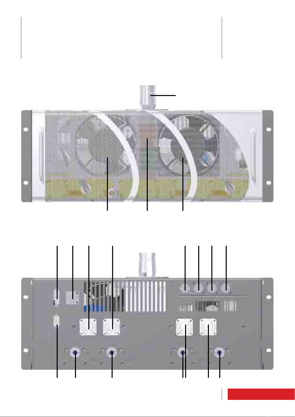
2.1 Combiner/Splitter unit

16 Product description
1 FAN - cooling fans. There are two, 12-28Vdc, 306M3/h max.
2 GRILL - ventilation grille.
3 RF OUT - RF output connector 3”+1/8
4 PWS - 3W3 connector for the fan power supply.
5 AUX1 - unused connector.
6 SPLITTER IN - N connector for RF splitter input.
7 LOAD - four 7/16 connectors for unbalanced load outputs.
8 SPLITTER OUT - four N connectors for RF splitter outputs.
9 POWER IN - four 7/8 connectors for RF amplifier inputs.
17
1
2 3
4 5 6 7
9 10 11
11
12
13
14
15
16
17
18 19
20
2321
27 27262524
22
8
Product description
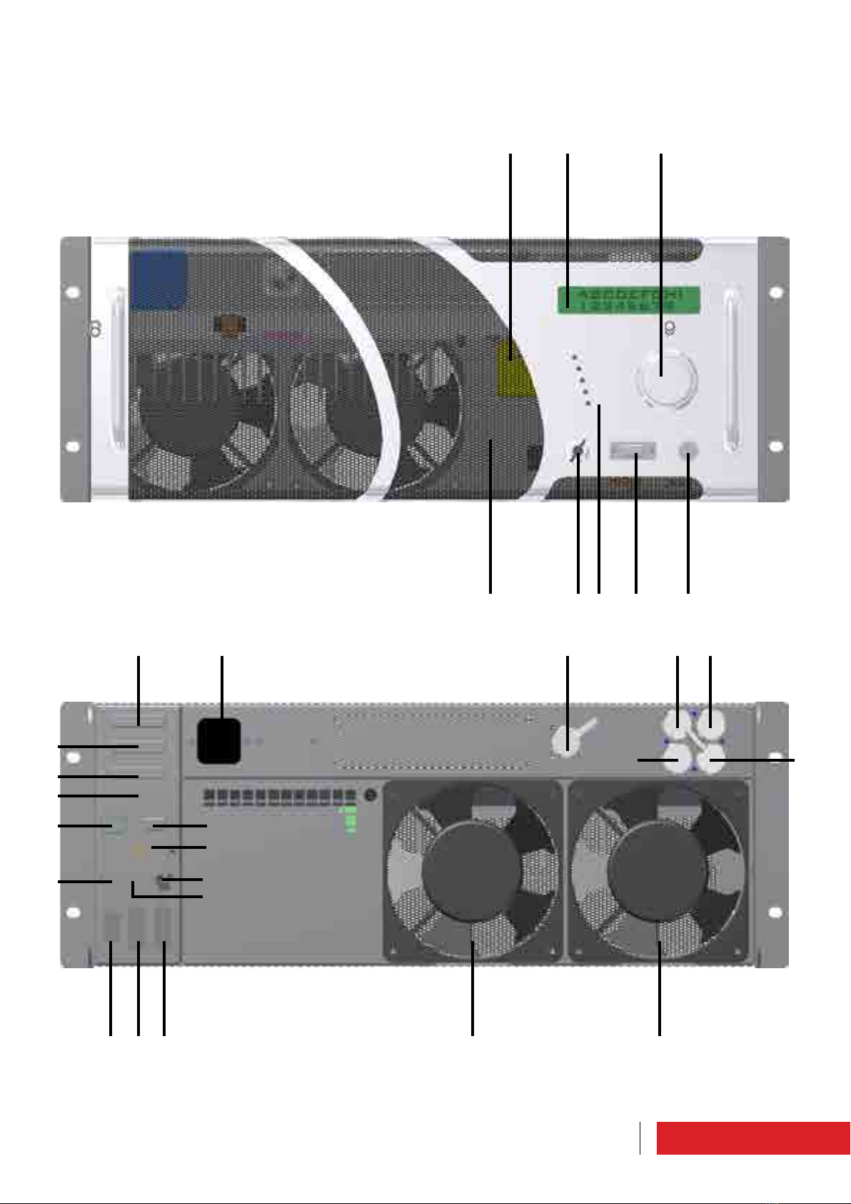
2.2 Control unit (ET30000-5, ET25000-5,
ET20000-5)

18 Product description
1 GRILL - ventilation grille.
2 DISPLAY - display showing the operating parameters and selected functions using the
encoder.
3 ENCODER - multifunction knob allowing navigation through the function menus and
modification of the operating parameters.
4 KEY SELECTOR - it can be set to LOCAL (controllable through the front panel) or REMO-
TE (controllable via PC) mode, by turning the key supplied with the equipment.
5 WARNING LIGHTS - LED list:
• FAULT (red) _ this warning light is on when the equipment is considered to be in
“FAILURE”;
• ON AIR (green) _ this warning light is on when the apparatus is broadcasting;
• ST-BY (yellow) _ this warning light is on when the apparatus is not broadcasting;
• LOCAL (blue) _ this warning light is on during local programming;
• MAINS (green) _ this warning light is on when power is supplied.
6 INTERFACE - B9 F connector for connection with telemetry according to the EIA485
standard, or to a PC.
7 RF MONITOR - BNC connector for connection with external measurement tools, al-
lowing to the RF signal to be taken at a low level (0dBm at scale bottom). This monitor
is not calibrated, therefore it is not guaranteed that the output level stays constant as
frequency changes. It CANNOT be used for measuring the output power, or for measu-
ring the harmonic components.
9 PROGRAMMING LEVER – Located on the right hand side of the panel facing the ma-
chine. It can be moved by means of a flat screwdriver upwards (in running mode) and
downwards (in program mode).
9 VDE - VDE socket for the equipment power supply.
10 EXCITER DUMMY LOAD - N connector for internal unbalanced load input.
11 RF IN - two N connectors for modulator RF inputs.
12 RF OUT - N connector for RF splitter output.
13 DUMMY LOAD - N connector for reserve exciter load.
14 PROFILES - DB25 F connector. Normally unused. It is used for the selection of profiles
stored (in the case of apparatus as a reserve).
15 TC/TS - DB25 F connector for remote control and remote telesignalling.
16 MASTER - DB25 F connector for interface with amplifiers and modulators.
17 SLAVE - unused connector.
18 INTERLOCK - unused connector.
19 IEEE485 - DB9 F connector for connection with telemetry according to the EIA485
standard.
20 AUX 1 - DB9 F connector for environment temperature probe.
21 FWD- BCN connector for forward power input.
22 REF - BNC connector for reflected power input.
23 MONITOR - BNC connector for low level signal input in antenna.
24 DUMMY LOAD - DB9 F connector for unbalanced load connection.
25 PWS DUMMY LOAD - 3W3 connector for the unbalanced load fan power supply.
26 PWS COMBINER - 3W3 connector for combiner fan power supply.
27 FAN - cooling fans. There are two, 12-28Vdc, 306M3/h max.
19
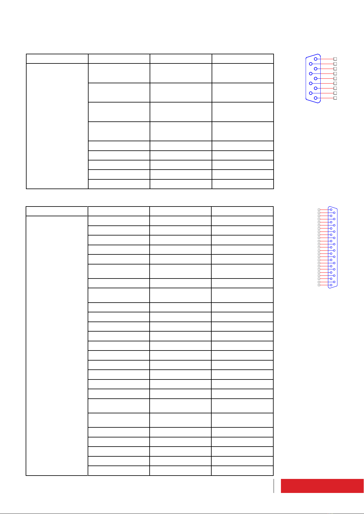
Connector Pin Meaning Notes
With a cable to CN3
on E3K 7A044 board 1 TX_1 Filtered output 485
Differential signal
“positive”
2 /TX_1 Filtered output 485
Differential signal
“negative”
3 RX_1 Filtered input 485
Differential signal
“positive”
4 / RX_1 Filtered input 485
Differential signal
“negative”
5 Common ground
6 Common ground
7 Common ground
8 Common ground
9 Common ground
Connector Pin Meaning Notes
CN1 on E10K5A070
board 1 TC_CH1 F_TC_CH0
2 TC_CH3 F_TC_CH2
3 TC_CH5 F_TC_CH4
4 - No connected
5 Common ground
6 TS_E_M_CH6 Common ground if JP4
is in shot circuit
7 - No connected
8 TS_E_M_CH3 Common ground if JP2
is in shot circuit
9 Common ground
10 Common ground
11 TS_CH5 F_TS_CH4
12 TS_CH F_TS_CH2
13 TS_CH1 F_TS_CH0
14 TC_CH2 F_TC_CH1
15 TC_CH4 F_TC_CH3
16 TC_CH6 F_TC_CH5
17 - No connected
18 Common ground
19 TS_E_M_CH5 Common ground if JP3
is in shot circuit
20 TS_E_M_CH4 Common ground if JP1
is in shot circuit
21 Common ground
22 Common ground
23 TS_CH6 F_TS_CH5
24 TS_CH4 F_TS_CH3
25 TS_CH2 F_TS_CH1
5
9
4
8
3
7
2
6
1
13
25
12
24
11
23
10
22
9
21
8
20
7
19
6
18
5
17
4
16
3
15
2
14
1
Product description
2.2.1 External connectors pin-out
2.2.1.1 Interface connector
2.2.1.2 Profiles connector

20
Connector Pin Meaning Notes
CN1
on E3K NA041board
1 Enable (interlock) Command to state
Pin grounded = active
command
500ms
2 TX ON Command pulse
Pin grounded = active
command
500ms
3 TX OFF Command pulse
Pin grounded = active
command
V4 Reflected power Output in voltage
See full scale values
5 Common ground Connected to the
frame
6RX- Com2 EIA485/422
7 - Not connected
8TX- Com2 EIA485/422
9 Common ground Connected to the
frame
V10 IPA (Current amplifier) Output in voltage
NOT USED
open
collector
11 Fault main Power supply FAULT
status
The pin must be pow-
ered externally.
“Open” Status -->
Fault active
open
collector 12 TX ON Signaling output
The pin must be pow-
ered externally.
“Closed to ground”
status --> TX ON
open
collector
13 Warning/Bad audio Signaling output
The pin must be pow-
ered externally.
“Closed to ground”
status --> Active
Warning
The operation is af-
fected by settings of
the machine
14 Reset alarm Command pulse
Pin grounded = active
command
15 - Reserved for Elenos
16 - Reserved for Elenos
V17 Forward power Output in voltage
See full scale values
18 Common ground Connected to the
frame
19 RX+ Com2 EIA485/422
20 TX+ Com2 EIA485/422
21 Common ground Connected to the
frame
V
22 VPA (Voltage ampli-
fier) Output in voltage
NOT USED
13
25
12
24
11
23
10
22
9
21
8
20
7
19
6
18
5
17
4
16
3
15
2
14
1
Product description
2.2.1.3 TC/TS connector
This manual suits for next models
7
Table of contents
Other Elenos Transmitter manuals


Popular Transmitter manuals by other brands


Adeunis RF
Adeunis RF SIGFOX-EUROPE user guide

ABB
ABB 266 MODBUS Operating instruction

HumanTechnik
HumanTechnik combi II operating instructions

Transmitter Solutions
Transmitter Solutions Stinger2 310LID22V manual

Flight Display Systems
Flight Display Systems FD900X3B Installation and operation manual

Shure
Shure ULX-D Series manual


